Advertisement
Table of Contents
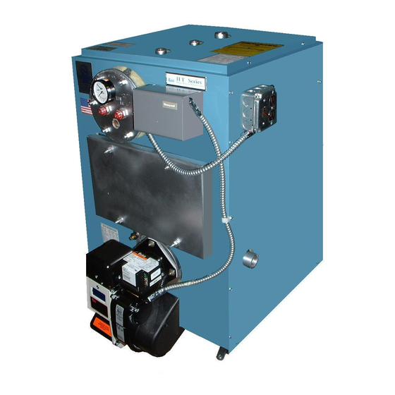
HT Series
Models HT 90/100/110, HT
V 90/100/110, HT 125/135/150
HT
V 125, HT 165/175/200 and HT 225/250/275
Installation
Operation
Maintenance
Manual
Thermo-Dynamics oiler Company
ROUTE 61 • P.O. BOX 325 • SCHUYLKILL HAVEN, PA 17972
TEL (570) 385-0731 • FAX (570) 385-5304
WEB www.thermodynamicsboiler.com • EMAIL sales@thermodynamicsboiler.com
Advertisement
Table of Contents

Related Manuals for Thermo-Dynamics Boiler HT 90 Series


Summary of Contents for Thermo-Dynamics Boiler HT 90 Series
- Page 1 HT Series Models HT 90/100/110, HT V 90/100/110, HT 125/135/150 V 125, HT 165/175/200 and HT 225/250/275 Installation Operation Maintenance Manual Thermo-Dynamics oiler Company ROUTE 61 • P.O. BOX 325 • SCHUYLKILL HAVEN, PA 17972 TEL (570) 385-0731 • FAX (570) 385-5304 WEB www.thermodynamicsboiler.com •...
-
Page 2: Table Of Contents
PRODUCT FEATURES • ASME Coded Boiler Registered with National Board • Factory Mounted/Wired Burner and Controls • Fully Insulated Heat Exchanger with Powder-Coated Cabinet • Packaged with Standard Five Gallon per Minute Tankless Coil (Domestic Hot Water) • Equipped with Triple Aquastat, Circulator, and Temperature / Altitude Gauge •... -
Page 3: Service Policy
Thank you for purchasing the Thermo-Dynamics boiler. Again, it is our intent to provide you with a high quality trouble free product that will be part of your fam- ily for many years to come. -
Page 4: Homeower Information
HOMEOWNER INFORMATION Heating Contractor: Address: Phone No.: A) General Installation and service is to be done only by a certified and qualified technician. Never burn garbage or refuse in your boiler or leave combustible material around it. Do not allow the fuel tank to run out of oil. -
Page 5: Read This First
HEATING CONTRACTOR INFORMATION Read This First Installer must be a trained, experienced technician and should read all instructions before installation. Inspect the boiler, jacket and all components to be sure damage has not occurred in shipment. If damage is evident, do not install the boiler. Contact your distributor immediately. -
Page 6: Model Specifications
MODEL SPECIFICATIONS Table 1 - Series I Boilers Model 90/100/110* Model 125/135/150* ___________________________________________________________________________________ Input 126,000 140,000 154,000 175,000 189,000 210,000 ___________________________________________________________________________________ Heat Capacity 109,000 121,000 132,000 150,000 161,000 178,000 ___________________________________________________________________________________ Gross Output ___________________________________________________________________________________ Net Out 95,000 105,000 115,000 130,000 140,000 155,000 ___________________________________________________________________________________ Firing Rate... - Page 7 MODEL DIMENSIONS FIGURE 2 - SERIES I BOILERS AQUASTAT RELAY 1-1/4" RETURN INLET/CIRCULATOR PIPED EITHER SIDE T/A GAUGE 1-1/4" SUPPLY OUTLET 6" FLUE OUTLET (CHIMNEY VENT) 5" FLUE OUTLET (DIRECT VENT) 30 5/8 37 7/16 29 3/16 13 1/8 10 3/4 4 3/4 22 3/4 22 1/16...
-
Page 8: Installation
Installation/Qualified Heating Contractor Only A) GENERAL The installation of the unit shall be in accordance with state and local regulations. B) FREIGHT CLAIMS All units should be inspected for damage upon arrival. Concealed damage claims should be filed immediately against the carrier by the consignor. The carrier is responsible for taking prompt action on all claims. - Page 9 1. Utility Room or Closet In buildings of tight construction, including most modern homes, you should provide an opening, connecting to a well ventilated attic, crawl space or directly with the outdoors. The opening should have a minimum free area of 1 square inch per 1,000 Btu per hour of total input for all appliances in the enclosure and should terminate below the burner level.
- Page 10 G) JACKET AND TRIM ASSEMBLY 1. Knock Down Boiler a. Jacket Assembly - Unpack the jacket parts being careful not to damage the finish. Piping and accessories are installed after the jacket is in place. b. Trim Assembly Install the safety relief valve in the 3/4" tapping in the top of the boiler. The relief valve should be piped to a safe place of discharge.
- Page 11 FIGURE 6 - PIPING DIAGRAM FOR SERIES I BOILERS WATER SUPPLY BALL VALVE BACK FLOW PREVENTER PRESSURE REDUCING VALVE HYDRONIC SYSTEM SUPPLY TEMPERED AIR VENT WATER STOP VALVE FLOW VALVE (SHOWERS AND FAUCETS) HOT WATER (DISHWASHER) EXPANSION TANK RETURN DOMESTIC ALTERNATE RETURN LOCATED COLD WATER RELIEF VALVE...
- Page 12 J) BURNER AND CONTROLS 1. Burner Installations Packaged boilers are shipped with the burner installed and prewired. Boilers that are shipped knocked-down must be field assembled. Follow the procedures listed below to install and connect the burner. a. Remove the burner parts and instructions from the carton. b.
- Page 13 Post-purge of the oil burner is controlled through the electronic circuitry supplied. Post-purge tim- ing is variable. The factory set post-purge timing is at approximately one minute. It is recom- mended that it be left at this setting. In no case should the post purge timing be reduced to less than 1 minute.
- Page 14 K) SEQUENCE OF OPERATION Forced Circulation Hot Water System with Tankless Heater When room temperature falls below thermostat setting, the thermostat calls for heat start- ing the circulating pump. The burner and pump continue to operate until room heating require- ments are satisfied (thermostat setting is reached), or until boiler water temperature reaches high limit control temperature setting.
- Page 15 M) FLUE SYSTEM - CHIMNEY VENT APPLICATIONS 1. General NOTE: An oil fired unit shall be connected to a flue having sufficient draft at all times to assure proper operation. 2. Draft The draft regulator should be installed in accordance with the manufacturers instructions. Set the draft to negative .02 to .04 inches W.C.
-
Page 16: Operation
3. A separate service box with disconnect switch is provided, wired but not fastened to the jack- et. Connect the service box to the jacket using the hole and screw provided. O) WARRANTY NOTE: The limited warranty is not applicable unless these installation instructions are followed. - Page 17 2. Burner Adjustments Allow the burner to operate steadily for at least 15 minutes. Check the burner settings according to the installer/serviceman labels for Series I and II boilers at the end of this manual, and make the following adjustments: a.
-
Page 18: Maintenance
Maintenance/Qualified Heating Technician Only A) VENT SYSTEM DANGER: ESCAPING GASES ARE DANGEROUS. THE ENTIRE FLUE AND VENTING SYSTEM SHOULD BE INSPECTED AT LEAST ONCE A YEAR BY A QUALIFIED SER- VICEMAN. B) OIL FILTER The oil filter cartridge should be replaced annually. C) CLEANING The heat exchanger and combustion chamber should be examined annually for scale and soot accumulation. -
Page 19: Trouble Shooting
Troubleshooting Guide/Qualified Heating Technician Only TROUBLE: BURNER DOES NOT START SOURCE PROCEDURE CAUSES REMEDY Thermostat Check Thermostat Thermostat set too low. Turn thermostat up. Thermostat on“off ”or“cool.” Switch to heat. Open thermostat wires. Repair or replace wires. Loose thermostat connectors. Tighten connection. - Page 20 TROUBLE: BURNER STARTS BUT DOES NOT ESTABLISH FLAME SOURCE PROCEDURE CAUSES REMEDY Empty tank. Fill tank. Oil Supply Check tank for oil. Water in oil tank. Strip tank of water exceeding Check for water in oil tank using a dip stick coated with litmus 2"...
- Page 21 TROUBLE: BURNER FIRES, BUT THEN FAILS ON SAFETY SOURCE PROCEDURE CAUSES REMEDY Faulty or dirty cad cell Clean or replace cad cell. Cad Cell Check cad cell with ohmmeter. If more than 2000 ohms, cad cell is defective or dirty. Faulty primary control Replace primary control.
- Page 22 TROUBLE: BURNER FIRES, BUT THEN LOSES FLAME SOURCE PROCEDURE CAUSES REMEDY Poor Fire Inspect flame for stability. Unbalanced fire. Replace nozzle with specified nozzle. Excessive draft. Reduce draft setting. Insufficient draft. Increase draft. Insufficient combustion air sources. Increase combustion air sources. Oil Supply If burner loses flame prior to the Air leak in fuel system.
- Page 23 TROUBLE: BURNER FIRES, BUT PULSATES SOURCE PROCEDURE CAUSES REMEDY Draft Take a draft reading. Draft should Down drafts. Install vent cap. be according to installer/service- Insufficient draft. Increase draft setting. man labels for Series I & II boiler. Excessive draft. Reduce draft settings, install second draft regulator if necessary.
- Page 24 TROUBLE: INSUFFICIENT HEAT SOURCE PROCEDURE CAUSES REMEDY Circulator Check if circulator is operational. Coupling worn or broken. Replace coupling. Pump binding. Replace pump. Circulator motor burned out. Replace circulator motor. Wiring from operating control Repair wiring. defective. Operating control defective. Repair or replace operating control.
- Page 25 TROUBLE: HIGH NET STACK TEMPERATURES SOURCE PROCEDURE CAUSES REMEDY Nozzle Check pump pressure with pump Nozzle overfiring due to high Reduce pump pressure according gauge. pump pressure. to installer/serviceman labels for Series I & II boilers starting on page 30. Heat Check heat exchanger surfaces Heat exchanger fouled.
-
Page 27: Parts List
PARTS LIST For Models 90/100/110 & 125/135/150 (Designate boiler and burner model numbers on all orders). Item No. Description Part No. 90/100/110 Heat Exchanger 241800 125/135/150 Heat Exchanger 241810 HT 6" Flue Box (Chimney Vent) 241128 HT 5" Flue Box (Direct Vent) 241129 Rear Refractory - Molded, Target Wall Only 337910... - Page 28 PARTS LIST For Models 165/175/200 & 225/250/275 (Designate boiler and burner model numbers on all orders). Item No. Description Part No. 165/175/200 Heat Exchanger 241820 225/250/275 Heat Exchanger 241825 Flue Box 241366 Rear Refractory - Molded, Target Wall Only 337416 Rear Cover with Molded Refractory Assembly 241360 Coil Plate - Blank...
-
Page 29: Preliminary Settings
PRELIMINARY SETTINGS INSTALLER/SERVICEMAN INSTALLER/SERVICEMAN Model Number HT-90 HT-100 HT-110 Model Number HT-90 HT-100 HT-110 ________________________ ________________________ Burner Type Beckett Beckett Beckett Burner Type Beckett Beckett Beckett Burner Model AFII AFII AFII Burner Model ________________________ ________________________ Nozzle Type .75 60B .85 60B .90 60B Nozzle Type .75 80°B... - Page 30 INSTALLER/SERVICEMAN INSTALLER/SERVICEMAN Model Number HT-90DV HT-100DV HT-110DV Model Number HT-90DV HT-100DV HT-110DV ________________________ ________________________ Burner Type Carlin* Carlin* Carlin* Burner Type Beckett Beckett Beckett Burner Model EZ-1 EZ-1 EZ-1 Burner Model AFII AFII AFII ________________________ ________________________ Nozzle Type .75 60A .85 60A .90 60A Nozzle Type...
- Page 31 INSTALLER/SERVICEMAN INSTALLER/SERVICEMAN Model Number HT-90 HT-100 HT-110 Model Number HT-125 HT-135 HT-150 ________________________ ________________________ Burner Type Beckett Beckett Beckett Burner Type Beckett Beckett Beckett Burner Model Burner Model ________________________ ________________________ Nozzle Type 0.70 60°B 0.75 60°B 0.85 60°B Nozzle Type 1.00 80°B 1.10 80°B 1.25 80°B ________________________...
- Page 32 INSTALLER/SERVICEMAN INSTALLER/SERVICEMAN Model Number HT-125 HT-135 HT-150 Model Number HT DV-125 HT DV-125 HT DV-125 ________________________ ________________________ Burner Type Riello Riello Riello Burner Type Beckett Carlin* Riello Burner Model Burner Model AFII EZ-1 ________________________ ________________________ Nozzle Type 1.00 60B 1.10 60B 1.25 60B Nozzle Type 1.00 60°B...
- Page 33 INSTALLER/SERVICEMAN INSTALLER/SERVICEMAN Model Number HT-90 HT-100 HT-110 Model Number HT-90DV HT-100DV HT-110DV ________________________ ________________________ Burner Type Beckett Beckett Beckett Burner Type Beckett Beckett Beckett Burner Model Burner Model ________________________ ________________________ Nozzle Type 0.70 60°B 0.75 60°B 0.85 60°B Nozzle Type 0.70 60°B 0.75 60°B 0.85 60°B ________________________...
-
Page 34: Wiring Diagrams
ELECTRICAL DIAGRAM FOR HT SERIES BOILERS TO CONNECT BURNER TO AQUASTAT (APPLIES TO BECKETT CHIMNEY VENT BURNERS) - Page 35 ELECTRICAL DIAGRAM FOR HT SERIES BOILERS TO CONNECT BURNER TO AQUASTAT (APPLIES TO BECKETT DIRECT VENT BURNERS)
- Page 36 ELECTRICAL DIAGRAM FOR HT SERIES BOILERS TO CONNECT BURNER TO AQUASTAT (APPLIES TO CARLIN CHIMNEY VENT AND CARLIN DIRECT VENT BURNERS)
- Page 37 ELECTRICAL DIAGRAM FOR HT SERIES BOILERS TO CONNECT BURNER TO AQUASTAT (APPLIES TO RIELLO CHIMNEY VENT BURNERS)
- Page 38 ELECTRICAL DIAGRAM FOR HT SERIES BOILERS TO CONNECT BURNER TO AQUASTAT (APPLIES TO RIELLO DIRECT VENT BURNERS)
-
Page 39: Warranty
FIRST YEAR, LIMITED WARRANTY, RESIDENTIAL WATER BOILERS oxygen attack), (h) leaky gaskets, (i) improper water conditioning, (k) Thermo-Dynamics Boiler Company (“Thermo”) warrants to the origi- improper maintenance of external and fireside surfaces. nal consumer purchaser (“purchaser”) that its residential water boiler is free 5. -
Page 40: Burner Service Set-Up Records
bURNER SERVICE SET-UP RECORDS Initial Set Up 1. Date 2. Model Number 3. Firing Rate 4. Pump Pressure* 5. CO2 6. “0” Smoke 7. Gross Stack°F 8. Draft Over Fire 9. Replaced Filter Yes/No 10. Replaced Nozzle Yes/No 11. Clean Pump Filter Yes/No 12.
Need help?
Do you have a question about the HT 90 Series and is the answer not in the manual?
Questions and answers