Table of Contents
Advertisement
Quick Links
Advertisement
Table of Contents

Related Manuals for Thermo-Dynamics Boiler LM Series


Summary of Contents for Thermo-Dynamics Boiler LM Series
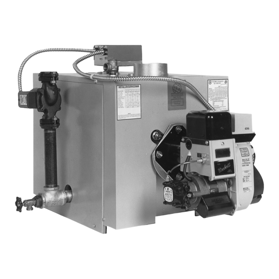
- Page 1 LM Series Low Mass Boiler LM Boiler LMD, Direct Vent Boiler Installation Operation Maintenance Manual Thermo-Dynamics Boiler Company 155 ROUTE 61 SOUTH • SCHUYLKILL HAVEN, PA 17972 TEL (570) 385-0731 • FAX (570) 385-5304 WEB www.thermodynamicsboiler.com • EMAIL sales@thermodynamicsboiler.com...
-
Page 3: Table Of Contents
PRODUCT FEATURES • ASME Coded Boiler Registered with National Board • Factory Mounted/Wired Burner and Controls • Fully Insulated Heat Exchanger with Powder-Coated Cabinet • Burner swings for easy cleaning • Equipped with Hydronic Control, Circulator, and Temperature / Altitude Gauge •... -
Page 4: Service Policy
Thank you for purchasing the Thermo-Dynamics boiler. Again, it is our intent to provide you with a high quality trouble free product that will be part of your family for many years to come. -
Page 5: Homeowner Information
HOMEOWNER INFORMATION Heating Contractor: Address: Phone No.: A) General Installation and service is to be done only by a certified and qualified technician. Never burn garbage or refuse in your boiler or leave combustible material around it. Do not allow the fuel tank to run out of oil. -
Page 6: Heating Contractor Information
HEATING CONTRACTOR INFORMATION Read This First Installer must be a trained, experienced technician and should read all instructions before installation. Inspect the boiler, jacket and all components to be sure damage has not occurred in shipment. If damage is evident, do not install the boiler. Contact your distributor immediately. -
Page 7: Model Specifications
MODEL SPECIFICATIONS FIGURE 1 SPECIFICATIONS LM-75 LM-85 LM-100 LM-110 LM-125 LMD-75 LMD-85 LMD-100 LMD-110 LMD-125 INPUT BTU/HR 105,000 119,000 140,000 154,000 175,000 HEATING CAPACITY BTU/HR 91,000 102,000 121,000 133,000 151,000 NET RATING BTU/HR 79,000 89,000 105,000 115,000 131,000 INPUT #2 OIL GPH 0.75 0.85 1.00... -
Page 8: Installation
INSTALLATION/QUALIFIED HEATING CONTRACTOR ONLY A) GENERAL The installation of the unit shall be in accordance with state and local regulations. B) FREIGHT CLAIMS All units should be inspected for damage upon arrival. Concealed damage claims should be filed imme- diately against the carrier by the consignor. The carrier is responsible for taking prompt action on all claims. - Page 9 INSTALLATION/QUALIFIED HEATING CONTRACTOR ONLY Place the tank stand on a level floor in its proper location before setting the boiler on top. If the floor is not level be sure to level the stand by inserting metal shims under the tank stand legs. Once the boiler is positioned on the stand do not attempt to move the stand.
- Page 10 2. Basement a. When a boiler is installed in a full basement, infiltration is normally adequate to provide air for combustion. b. In buildings of tight construction when the basement windows are weather stripped, one open- ing to a well ventilated attic or with the outdoors should be provided. (See part 1 for opening requirements) 3.
- Page 11 below the top or waterline of the boiler, thus allowing only air free water to enter the supply to the heating system. The air trapped in the top of the boiler is then purged through a 3/4" vent tapping to be released with an (1) automatic float vent (2) a manual vent or (3) piped into a conven- tional type expansion tank.
- Page 12 FIGURE 4 - PIPING LAYOUT PREFERRED AND ALTERNATE METHODS CIRCULATOR AIR VENT OR EXPANSION TANK SUPPLY FLOW CONTROL SUPPLY VALVE FLOW CONTROL VALVE AQUASTAT AIR VENT OR T & A GAUGE EXPANSION TANK RELIEF THERMOSTATIC OR VALVE MANUAL BYPASS AQUASTAT T &...
- Page 13 J) BURNER AND CONTROLS 1. Burner Installations Packaged boilers are shipped with the burner installed and prewired. Boilers that are shipped knocked-down must be field assembled. Follow the procedures listed below to install and connect the burner. a. Remove the burner parts and instructions from the carton. b.
- Page 14 Length of Vent Kit Minimum Post Purge Time 0 - 10 Feet 1 Minute 10.1 - 15 Feet 1 Minute 15.1 - 20 Feet 2 Minutes Times are approximate and should be considered minimum settings for the length of intake pipe installed.
- Page 15 K) SEQUENCE OF OPERATION When room temperature or the indirect water heater temperature falls below the thermostat set- ting, the thermostat calls for heat starting the burner and circulating pump. The burner and pump continue to operate until room heating requirements are satisfied. If the boiler high limit is reached the burner will shut off with the circulator continuing to oper- ate.
- Page 16 M) FLUE SYSTEM - CHIMNEY VENT APPLICATIONS 1. General NOTE: An oil fired unit shall be connected to a flue having sufficient draft at all times to assure proper operation. 2. Draft The draft regulator should be installed in accordance with the manufacturers instructions. Set the draft to negative .02 to .04 inches W.C.
-
Page 17: Operation
1. Field connections should be protected with a 15 amp fuse. 2. Install the room thermostat on an inside wall away from cold drafts, windows, or heat from fireplaces, appliances, or sunlight. Connect the thermostat leads to the “TT” terminals on the cir- culator control. - Page 18 2. Burner Adjustments Allow the burner to operate steadily for at least 15 minutes. Check the burner settings according to the installer/serviceman labels for boilers at the end of this manual, and make the following adjustments: a. Sampling Hole - A 1/4" hole in the flue pipe is provided. All test readings should be taken from this point.
-
Page 19: Maintenance
Maintenance/Qualified Heating Technician Only A) VENT SYSTEM DANGER: ESCAPING GASES ARE DANGEROUS. THE ENTIRE FLUE AND VENTING SYSTEM SHOULD BE INSPECTED AT LEAST ONCE A YEAR BY A QUALIFIED SER- VICEMAN. At the beginning of each heating season, boiler flue passages and the oil burner should be checked for cleanliness and if necessary they should be cleaned. -
Page 20: Trouble Shooting
Troubleshooting Guide/Qualified Heating Technician Only TROUBLE: BURNER DOES NOT START SOURCE PROCEDURE CAUSES REMEDY Check Thermostat Thermostat set too low. Turn thermostat up. Thermostat Thermostat on “off ” or “cool.” Switch to heat. Open thermostat wires. Repair or replace wires. Loose thermostat connectors. - Page 21 TROUBLE: BURNER STARTS BUT DOES NOT ESTABLISH FLAME SOURCE PROCEDURE CAUSES REMEDY Check tank for oil. Empty tank. Fill tank. Oil Supply Check for water in oil tank using Water in oil tank. Strip tank of water exceeding 2" in depth. a dip stick coated with litmus paste.
- Page 22 TROUBLE: BURNER FIRES, BUT THEN FAILS ON SAFETY SOURCE PROCEDURE CAUSES REMEDY Faulty or dirty cad cell Clean or replace cad cell. Check cad cell with ohmmeter. If Cad Cell more than 2000 ohms, cad cell is defective or dirty. Faulty primary control Replace primary control.
- Page 23 TROUBLE: BURNER FIRES, BUT THEN LOSES FLAME SOURCE PROCEDURE CAUSES REMEDY Unbalanced fire. Replace nozzle with specified Inspect flame for stability. Poor Fire nozzle. Excessive draft. Reduce draft setting. Insufficient draft. Increase draft. Insufficient combustion air sources. Increase combustion air sources. If burner loses flame prior to the Air leak in fuel system.
- Page 24 TROUBLE: BURNER FIRES, BUT PULSATES SOURCE PROCEDURE CAUSES REMEDY Down drafts. Install vent cap. Take a draft reading. Draft should Draft be according to installer/service- Insufficient draft. Increase draft setting. man labels for Series I & II boiler. Excessive draft. Reduce draft settings, install second draft regulator if necessary.
- Page 25 TROUBLE: INSUFFICIENT HEAT SOURCE PROCEDURE CAUSES REMEDY Coupling worn or broken. Replace coupling. Check if circulator is operational. Circulator Pump binding. Replace pump. Circulator motor burned out. Replace circulator motor. Wiring from operating control Repair wiring. defective. Operating control defective. Repair or replace operating control.
- Page 26 TROUBLE: HIGH NET STACK TEMPERATURES SOURCE PROCEDURE CAUSES REMEDY Check pump pressure with pump Nozzle overfiring due to high Reduce pump pressure according Nozzle gauge. pump pressure. to installer/serviceman labels for Series I & II boilers starting on page 30. Check heat exchanger surfaces Heat exchanger fouled.
-
Page 27: Parts List
Parts List LM75/85 and LM100/110/125 Boilers Item Description Part Number Part Number LM75/100 LM110/135 Fire Tube Baffle 817100 280274 Combustion Liner 337804 337804 Burner Door Steel 280264 280264 Insulation for Steel Burner Door 337818 337818 Target Wall Insulation 337816 337816 Rear Door 280269 280269... -
Page 28: Preliminary Settings
Preliminary Settings INSTALLER/SERVICEMAN INSTALLER/SERVICEMAN Model Number LM-75 LM-85 Model Number LM-75 LM-85 Burner Type Riello Riello Burner Type Beckett Beckett Burner Model Burner Model AFII AFII Nozzle Type .65 60W 0.75 60W Nozzle Type .65 70B 0.75 70B Pump Pressure PSI Pump Pressure PSI Head/Pin Position Head/Pin Position... - Page 29 INSTALLER/SERVICEMAN INSTALLER/SERVICEMAN Model Number LM-75 LM-85 Model Number LMD-75 LMD-85 Burner Type Riello Riello Burner Type Beckett Beckett Burner Model Burner Model Nozzle Type .60 60°B 0.70 60°B Nozzle Type .65 60W 0.75 60W Pump Pressure PSI Pump Pressure PSI Head/Pin Position Head/Pin Position Air Band...
- Page 30 INSTALLER/SERVICEMAN INSTALLER/SERVICEMAN Model Number LMD-75 LMD-85 Model Number LM-100 LM-110 LM-125 ________________________ Burner Type Riello Riello Riello Burner Type Beckett Beckett Burner Model Burner Model ________________________ Nozzle Type .60 60°B 0.70 60°B Nozzle Type ________________________ 0.85 60A .90 60A 1.00 60A Pump Pressure PSI Pump Pressure PSI ________________________...
- Page 31 INSTALLER/SERVICEMAN INSTALLER/SERVICEMAN Model Number Model Number LM-100 LM-110 LM-125 ________________________ ________________________ LM-100 LM-110 LM-125 Burner Type Beckett Beckett Beckett Burner Type Beckett Beckett Beckett Burner Model AFII AFII AFII Burner Model ________________________ ________________________ Nozzle Type ________________________ Nozzle Type ________________________ 0.75 60°B 0.85 60°B .90 60°B 0.85 60B...
- Page 32 INSTALLER/SERVICEMAN INSTALLER/SERVICEMAN Model Number LMD-100 LMD-110 LMD-125 Model Number LMD-100 LMD-110 LMD-125 ________________________ ________________________ Burner Type Carlin Carlin Carlin Burner Type Riello Riello Riello Burner Model ________________________ EZ-1 EZ-1 EZ-1 Burner Model ________________________ BF-5 BF-5 BF-5 Nozzle Type 0.85 60°B 0.90 60°B 1.00 60°B Nozzle Type...
-
Page 35: Burner Service Set-Up Records
BURNER SERVICE SET-UP RECORDS Initial Set Up 1. Date 2. Model Number 3. Firing Rate 4. Pump Pressure* 5. CO2 6. “0” Smoke 7. Gross Stack°F 8. Draft Over Fire 9. Replaced Filter Yes/No 10. Replaced Nozzle Yes/No 11. Clean Pump Filter Yes/No 12.
Need help?
Do you have a question about the LM Series and is the answer not in the manual?
Questions and answers