
Related Manuals for Thermo-Dynamics Boiler S85


Summary of Contents for Thermo-Dynamics Boiler S85
- Page 1 S Series Installation Operation Maintenance Manual www.thermodynamicsboiler.com Thermo-Dynamics oiler Company ROUTE 61 • SCHUYLKILL HAVEN, PA 17972 (570) 385-0731 FAX (570) 385-5304...
-
Page 2: Service Policy
Thank you for purchasing the Thermo-Dynamics boiler. Again, it is our intent to provide you with a high quality trouble free product that will be part of your family for many years to come. -
Page 3: Table Of Contents
Contents Subject Page Read This First ........... . . 2 Specifications . -
Page 4: Read This First
Read This First Installer must be a trained, experienced technician and should read all instructions before installation. Inspect the boiler, jacket and all components to be sure damage has not occurred in shipment. If damage is evident a claim must be filed with the freight carrier who transported the boiler from the factory to the distributor where it was purchased. - Page 5 10. The use of low sulfur No. 2 heating oil is highly recommended. 11. Modification, substitution or elimination of factory equipped, supplied or specified components may result in property damage, personal injury or the loss of life. 12. The following definitions apply to potential hazards noted in this manual. DANGER: Indicates a hazardous situation which if not avoided will result in death or serious injury.
-
Page 6: Installation
A. Installation Instructions 1) Place the boiler on a level floor, preferably raised and as close to the chimney as possible. The boiler must be installed on a non-combustible surface. The minimum clearances for installation are shown below. Reduced clearance installations must follow NFPA-31 guidelines. -
Page 7: Specifications
valve (tempering valve), not supplied, must be used to reduce the water temperature at kitchen or bathroom taps. High temperature water for a dishwasher may be obtained by piping as shown in the Installation Drawing. The nuts that secure the tank-less coil flange should be tightened before the boiler is filled with water, after initial firing and once a year during the annual maintenance. - Page 8 FUEL UNITS/FUEL LINES Fuel supply "level with" or "above" burner: A single stage fuel unit connected to the fuel sup- ply with a single supply line is the most common type of installation for these conditions. Manual venting of the fuel unit is usually required on initial start-up. Failure to vent air could result in an air lock/oil starvation condition.
-
Page 9: Operational Sequence
11) Connect the electric supply to the boiler as indicated on the wiring diagram. The wiring must be installed in accordance with the National Electrical Code and any other state and local codes and the following requirements. Internal wiring is completed at the factory on packaged boilers. External wiring must con form with the National Electric Code and local codes. -
Page 10: Start-Up
2) S boilers not equipped with a tankless coil are may be provided with a high limit aquastat control which should be set at 180°F by the installer. This setting is nominal and may be adjusted for the particular installation conditions. a. - Page 11 5) Install pressure gauge in the port provided on the oil pump. Attach a length of 1/4" O.D. clear plastic tubing to the end of the bleed plug. 6) Turn on power to the boiler. If burner does not start immediately reset manual overload switches and control.
- Page 12 d. Follow the burner manufacturer’s instructions to adjust the air supply until a trace of smoke is recorded. At the trace of smoke level, measure the CO2. This is the reference point for all further adjustments. e. Increase the air supply to reduce the CO2 about 1 ? % to 2% from the reference point. A zero smoke reading should result.
- Page 13 G) Check all refractory and gaskets for resilience and continuity. Replace damaged parts prior to re-assembling the unit. H) Reassemble the boiler. 8) Replacing the combustion chamber. In the event that the combustion chamber is replaced, follow these instructions. A) Turn off power to the boiler and burner and shut off the oil supply to the burner. B) Remove the burner assembly from the base.
-
Page 14: Troubleshooting Guide
Troubleshooting Guide TROUBLE: BURNER DOES NOT START SOURCE PROCEDURE CAUSE REMEDY Thermostat Check thermostat settings Thermostat set too low. Turn thermostat up. Thermostat on “off or “cool”. Switch to heat. Open thermostat wires. Repair or replace wires. Loose thermostat connectors. Tighten connection. - Page 15 TROUBLE: BURNER STARTS BUT DOES NOT ESTABLISH FLAME SOURCE PROCEDURE CAUSES REMEDY Check tank for oil. Empty tank. Fill tank. Supply Check for water in oil tank Water in oil tank. Strip tank of water exceeding using a dip stick coated 2"...
- Page 16 TROUBLE: BURNER FIRES, BUT THEN LOSES FLAME SOURCE PROCEDURE CAUSES REMEDY Poor Fire Inspect flame for stability. Unbalanced fire. Replace nozzle with specified nozzle. Excessive draft. Reduce draft setting. Insufficient draft. Increase draft. Too little combustion air. Increase combustion air. Oil Supply If burner loses flame prior to Air leak in fuel system.
- Page 17 TROUBLE: BURNER FIRES BUT PULSATES SOURCE PROCEDURE CAUSES REMEDY Draft Take a draft reading. Draft Down drafts. Install vent cap. should be -.05” -.06: W.C. in Insufficient draft. Increase draft setting. the stack. Excessive draft. Reduce draft settings, install second draft regulator if necessary.
- Page 18 TROUBLE: INSUFFICIENT HEAT SOURCE PROCEDURE CAUSES REMEDY Circulator Check if circulator is opera- Coupling worn or broken. Replace coupling. tional. Pump binding. Replace pump. Circulator motor burned out. Replace circulator motor. Wiring from operating Repair wiring. control defective. Operating control defective. Repair or replace operating control.
- Page 19 TROUBLE: TOO MUCH HEAT SOURCE PROCEDURE CAUSES REMEDY Circulator Check to see if operating Circulator does not stop Repair operating control. control is working properly. running. Thermostat Check thermostat settings and Thermostat set too high. Reset thermostat. calibration. Thermostat defective. Replace thermostat.
- Page 20 COIL & GAUGE BOILER TUBE SECTION RELIEF VALVE RETURN ASME HYDRONIC RETURN CHAMBER SECTION BACK FRONT Figure 1 Series imensions A - Jacket Height B - Jacket Width C - Jacket Length D Coil Height E - Hydronic Return Height F - Alt.
- Page 21 2-1-1/4" 2-1-1/4" AFUE*** 84.3 84.2 84.0 84.6 84.0 85.2 85.4 85.1 •Based on D.O.E. Test Procedures ••Coil capacity based on 5 min. draw. 5 min. waiting period. ***AFUE with vent damper - S85-110 2.5% higher, S125-150 1.4% higher Appendix C...
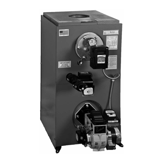
- Page 22 FLUE OUTLET ALTITUDE GAUGE HYDRONIC SUPPLY AQUASTAT RELAY AIR SCOOP VENT RELIEF VALVE ALTERNATE LIMIT ALTERNATE RETURN HYDRONIC RETURN INSPECTION PORT RATING DECAL EXTENDED TANKLESS COIL ASME TAG HIGH SPEED FLAME RETENTION BURNER PRIMARY CONTROL Series FLO-CONTROL VALVE AIR VENT GATE VALVE PRESSURE RED.
- Page 23 ELECTRICAL DIAGRAM FOR S SERIES BOILERS TO CONNECT BURNER TO AQUASTAT (APPLIES TO BECKETT CHIMNEY VENT BURNERS) ELECTRICAL DIAGRAM FOR S SERIES BOILERS TO CONNECT BURNER TO AQUASTAT (APPLIES TO CARLIN CHIMNEY VENT AND RIELLO CHIMNEY VENT BURNERS) Appendix E...
- Page 24 INSTALLER/SERVICEMAN INSTALLER/SERVICEMAN Model Number S-125 S-135 Model Number S-125 S-135 ________________________ ________________________ Burner Type Carlin Carlin Burner Type Riello Riello Burner Model EZ-1 EZ-1 Burner Model ________________________ ________________________ Nozzle Type 1.00 60A 1.10 60A Nozzle Type 1.00 60A 1.10 60A ________________________ ________________________ Pump Pressure PSI...
- Page 25 INSTALLER/SERVICEMAN INSTALLER/SERVICEMAN Model Number S-85 Model Number S-100 ________________________ ________________________ Burner Type Beckett Carlin Riello Burner Type Beckett Carlin Riello Burner Model AFG* EZ-1 Burner Model EZ-1 ________________________ ________________________ Nozzle Type 0.65 80B 0.65 60A 0.65 60A Nozzle Type 0.75 80B 0.75 60A 0.75 60A ________________________...
- Page 26 STR Energy Star Product INSTALLER/SERVICEMAN INSTALLER/SERVICEMAN Model Number STR-100 Model Number STR-85 ________________________ ________________________ Burner Type Beckett Carlin Riello Burner Type Beckett Carlin Riello Burner Model AFG* EZ-1 Burner Model EZ-1 ________________________ ________________________ Nozzle Type 0.65 80B 0.65 60A 0.65 60A Nozzle Type 0.75 80B 0.75 60A...
-
Page 27: Parts List
PARTS LIST (Designate boiler and burner model numbers on all orders.) Item No. Description Part No. Carlin EZ1 Burner 542210 Riello 5F Burner 6" Tube w.Primary 541167 Beckett AGF Burner 540545 Solid State Electronic Transformer 675981 F-3 Burner Head (S-85/110 AFG) 675400 F-12 Burner Head (S-125/150 AFG) 675420... - Page 28 Series Service Set-Up Records Initial Set Up 1. Date 2. Model Number 3. Firing Rate 4. Pump Pressure Set 140 PSI 5. CO 6. "O" Smoke 7. Gross Stack˚ 8. Draft Over Fire 9. Replaced Filter Yes/No 10. Replaced Nozzle Yes/No 11.
Need help?
Do you have a question about the S85 and is the answer not in the manual?
Questions and answers