
Related Manuals for Sunny Boy SWR 2500U


Summary of Contents for Sunny Boy SWR 2500U
-
Page 1: Sunny Boy
Sunny Boy SWR 2500U Installation and Operator’s Manual Issue 1.2 Grid Tied String Inverter for Photovoltaic Systems SB2500U-11:NE3801 http://www.wholesalesolar.com/inverters.html... - Page 2 Sunny Boy 2500U Installation and Operator’s Manual SB2500U-11:NE SMA Regelsysteme GmbH http://www.wholesalesolar.com/inverters.html...
-
Page 3: Important Safety Instructions
Sunny Boy. To reduce the risk of electrical shock, and to ensure the safe installation and operation of the Sunny Boy, the following safety symbols have been placed throughout this technical description to indicate dangerous conditions and im- portant safety instructions. - Page 4 • On top of the device you can find the heat sink of the Sunny Boy with potential temperatures of over 175°F (80 °C). To reduce the risk of burns, do not touch.
-
Page 5: Table Of Contents
Operation Indicator ..................27 Ground Fault Indicator ..................30 Failure Indication .................... 31 Opening and closing of the Sunny Boy............36 Upgrading or modification of the Sunny Boy interface ........39 Measuring Channels and Messages............... 41 Measurement Precision .................. 43 Troubleshooting ...................... 44 Warranty Regulations and Liability................ -
Page 6: Introduction
Installation and Operator’s Manual 1 Introduction The SMA Sunny Boy is a string inverter for grid tied operation. With this manual the Sunny Boy can be installed and operated in a safe way. This installer’s guide is used as reference for the commissioning and as guideline on how to use all functions of the inverter optimally and how you can extend your existing PV-plant. -
Page 7: Installation
Installation and Operator’s Manual 2 Installation WARNING: Before installing the Sunny Boy, read all instructions and cau- tionary markings in the technical description and on the Sunny Boy and the photovoltaic array. WARNING: All electrical installations shall be done in accordance with all local electrical codes and the National Electrical Code (NEC), ANSI/NFPA 70. -
Page 8: Placement Of The Sunny Boy
Installation and Operator’s Manual 2.2 Placement of the Sunny Boy The Sunny Boy is a sophisticated electronic device and is therefore sensitive to hu- midity within the case. NOTE: If the Sunny Boy is placed outside, the humidity during the installa- tion should be as low as possible - pay special attention that it does not rain. - Page 9 • Free air circulation around the case must not be obstructed. • If you are installing the Sunny Boy in a cabinet or closet etc., the air circulation must be sufficient for heat dissipation - provide external ventilation. •...
- Page 10 Sunny Boy 2500U Installation and Operator’s Manual The Sunny Boy inverter is mounted on the back side with the three metal straps. Drilling Template for the Sunny Boy 2000, 2500, 3000 distance between the holes on the top 217.50 mm...
- Page 11 Installation and Operator’s Manual Preparing the Mounting The Sunny Boy is mounted on its back side with the 3 metal straps. For that 3 screws and 3 according dowels (wall anchors) are necessary. The screws and dowels are not included. We recommend 6 mm screws and 8 mm dowels.
-
Page 12: Electric Connection
Sunny Boy 2500U Installation and Operator’s Manual 2.3 Electric Connection The electric connection of the Sunny Boy can be done once the device is correctly mounted in its position. Fig. 2.4: Simplified electrical wiring diagram of the PV-system GFDI-Fuse... - Page 13 Connect the DC disconnect enclosure to the Sunny Boy • Connect the utility by switching all breakers ON To disconnect the Sunny Boy from the system, first turn all breakers and switches OFF. Then disconnect the various conductors in the reverse order listed above. SB2500U-11:NE SMA Regelsysteme GmbH http://www.wholesalesolar.com/inverters.html...
-
Page 14: Preparation Of The Electric Connection
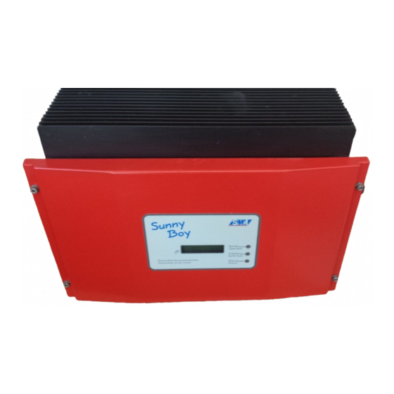
Fig. 2.6: Front view of the Sunny Boy 2500U You now have the opened Sunny Boy in front of you (see Fig. 2.7) and can see the position of components and clamps relevant for you. You will find: •... - Page 15 Sunny Boy 2500U Installation and Operator’s Manual AC-Connection Grid Fuse Resistors Place for Piggy Back DC-Connection Fig. 2.7: Interior of the Sunny Boy 2500U SB2500U-11:NE SMA Regelsysteme GmbH http://www.wholesalesolar.com/inverters.html...
-
Page 16: Connection To Electrical Utility Grid
The grid impedance value at the connection point should be as low as possible to avoid an increase of the AC-voltage to non-permissible values while the Sunny Boy feeds to the grid. This also results in a higher system efficiency. - Page 17 Pull the wires through the conduit into the interior of the Sunny Boy. • Connect the wire L1 to the terminal labeled L in the Sunny Boy (see Fig. 2.8). • Connect the wire L2 to the terminal labeled N in the Sunny Boy.
- Page 18 Sunny Boy 2500U Installation and Operator’s Manual Connection of the PV-panels to the DC disconnect enclosure WARNING: Completely cover the surface of all PV-arrays with opaque (dark) material before wiring them. PV-arrays produce electrical energy when ex- posed to light and could create a hazardous condition.
- Page 19 Install the DC conduit from the DC disconnect enclosure to the Sunny Boy. • Insert the conduit fitting in the very left opening of the Sunny Boy. Fasten the fitting on the inside of the Sunny Boy with the nut. Do the same at the DC dis- connect enclosure . •...
-
Page 20: Commissioning
3 Commissioning Safety Notice NOTE: Make sure that nothing is on top of the heat sink of the Sunny Boy when it is running. WARNING: The heat sink can get very hot - i. e. over 175 °F (80 °C). - Page 21 If the PV-panel is isolated from earth first the yellow and red LEDs and after approx. 20 seconds only the red LED is on at the Sunny Boy. If you have communication equipment you will be displayed the “GFDI-Fuse open” failure.
- Page 22 Installation and Operator’s Manual • The Sunny Boy switches to fully automatic normal operation. The green LED is blinking. Should the red LED still be on the GFDI-fuse is defective and has to be replaced. (You will find a description of the correct type in chapter 4.2.)
- Page 23 Sunny Boy 2500U Installation and Operator’s Manual If the input voltage is high enough the Sunny Boy should start to feed inverted PV- power fully automatically to the grid, once enough power is coming from the PV- modules. The design of the Sunny Boy makes sure that its internal consumption is as low as possible.
-
Page 24: Operation And Failure Indication Leds
The inverter goes to standby mode if the radiation and the result- ing electric input energy is too low and is therefore always ready for operation. Each time the Sunny Boy starts up it runs a number of self test and safety proce- dures which the user does not notice. - Page 25 Earth Fault Photovoltaik-Stringwechselrichter Störu ng Failure Photovoltaic string inverter Fig. 4.1: Front view of Sunny Boy 2500U Description of the symbols used in the following section: LED off LED on once per second LED on three times per second LED on with short interruptions (75% on, 25% off)
- Page 26 Sunny Boy 2500U Installation and Operator’s Manual LED indicator Operating condition Description green: standby (night) input voltage < 120 V red: yellow: green: initialization input voltage: 120 V ... 240 V red: yellow: green: stop changing operating condition or manually initi-...
-
Page 27: Operation Indicator
NOTE: In some seldom cases (bad weather, low solar radiation) the LEDs can go on all at once and off again. This “blinking” results from the fact that the incoming radiation is not high enough for the Sunny Boy to keep it stable. Note: This is not a malfunction! - Page 28 The Sunny Boy is checking the utility concerning its suitability for feeding electricity (start- ing voltage, starting time) and begins to monitoring. NOTE: If the Sunny Boy fails to connect to the utility 3 times in a row, it will wait for 10 minutes before the next attempt.
- Page 29 Operation Green LED on Red LED off Yellow LED off all LEDs are off The Sunny Boy is feeding the local electricity grid, either in “MPP“ or in „Constant - Volt- age“ operation. • „MPP“-operation (default setting): The Sunny Boy pushes the voltage from the PV-modules to the voltage with the maximum output power.
-
Page 30: Ground Fault Indicator
Sunny Boy 2500U Installation and Operator’s Manual 4.2 Ground Fault Indicator Isolation failure Green LED off Red LED on Yellow LED on This is the result of a ground fault of the PV panel. The inverter then has to indicate this condition and disconnect from the grid. -
Page 31: Failure Indication
This is a failure of the utility monitoring or the automatic disconnection device MSD. The Sunny Boy has detected a failure in the disconnection device and has suppressed the utility interaction on startup. The Sunny Boy must be checked by service personnel and can only be put back to operation after a thorough checkup. - Page 32 The yellow failure indication LED is on for 5 seconds, is out for 3 seconds and then blinks twice. The code is sent three times. If the failure persists the indication blinking code is repeated. The Sunny Boy is indicating a failure which has one of the following reasons: • Low grid voltage ( < V see table 9.2)
- Page 33 The code is sent three times. If the failure persists the indication begins once again. The Sunny Boy has detected a failure based on the utility impedance values. The criteria for the grid impedance is described in the section ”Islanding protection“ in the technical description of the Sunny Boy.
- Page 34 The input voltage is too high. The PV-panels are generating a voltage higher than the permissible specified voltage! WARNING: Disconnect the PV-Panels from the Sunny Boy immediately. Too high input voltage can destroy the Sunny Boy. Have the circuits of your PV-panels checked.
- Page 35 The code is sent three times. If the failure persists the indication is repeated. The Sunny Boy is in a condition that makes it impossible to return to normal operation and is most likely defective. NOTE: The Sunny Boy has to be checked by a qualified technician.
-
Page 36: Opening And Closing Of The Sunny Boy
When working on the Sunny Boy follow the instructions below: 1. Separate the Sunny Boy from the grid by opening the 240 Volt AC-circuit breaker in the main fusebox. WARNING: Make sure the main 240V breaker in the main utility breaker box is switched OFF. - Page 37 3. Take off the lid by removing screws 1 - 4 (see Fig. 2.6) on the lid (M5). You now have the opened Sunny Boy in front of you (see Fig. 2.7) and can see the posi- tion of components and clamps relevant for you. You will find: •...
- Page 38 When putting the lid on make sure the seal in the inner side of the lid is placed cor- rectly. When screwing the inner screws make sure that the thread in the Sunny Boy case is not damaged by tilted screws. Under certain conditions the enclosure type NEMA 4X cannot be guaranteed any more.
-
Page 39: Upgrading Or Modification Of The Sunny Boy Interface
The Sunny Boy is prepared for data transmission. By simply plugging on a piggy back module it supports transmission via Powerline, RS232 or RS485 interfaces. In order to install a new interface in the Sunny Boy a corresponding piggy back module has to be installed on the system control board. - Page 40 Connect the cables for RS232 or RS485. No cabling is necessary for Powerline commu- nication. Data cables are lead outside through the free opening at the bottom of the Sunny Boy. Please insert the PG16 screws into this opening and fasten them. •...
-
Page 41: Measuring Channels And Messages
Offset offset calibration of the electronics Waiting grid switching-on conditions are not fulfilled (yet) Grid monitoring checking grid (grid impedance) MPP-Search PV voltage is determined and set Sunny Boy is in MPP mode SB2500U-11:NE SMA Regelsysteme GmbH http://www.wholesalesolar.com/inverters.html... - Page 42 Sunny Boy 2500U Installation and Operator’s Manual V-Const Sunny Boy is in constant voltage MPP mode Derating reduction of the grid feeding power Disturbance failure Error messages F-Bfr-Srr communication between micro-controllers is failing F-EEPROM EEPROM cannot be read or written on...
-
Page 43: Measurement Precision
± 3 % energy yield E [kWh] 0...4,29* 10 Wmin 1 Wmin 20 Wmin ± 3 % 0,67 µ s operating hours h [h] 0...4,29*10 ± 0,1 % Table 4.1: Measurement accuracy of the Sunny Boy SB2500U-11:NE SMA Regelsysteme GmbH http://www.wholesalesolar.com/inverters.html... -
Page 44: Troubleshooting
PV-panels - pay attention to all safety measures listed in chapter 2 “Installation”. • check the blinking code on the lid of the Sunny Boy and compare the code with the blinking codes in chapter 4. Follow the countermeasures listed there, if necessary contact the installer. - Page 45 • number of modules in string • output power • open circuit voltage Use the original box the Sunny Boy was delivered in if it is necessary to send the Sunny Boy to the manufacturer. SB2500U-11:NE SMA Regelsysteme GmbH http://www.wholesalesolar.com/inverters.html...
-
Page 46: Warranty Regulations And Liability
Sunny Boy 2500U Installation and Operator’s Manual 6 Warranty Regulations and Liability Warranty The warranty period is 24 months from the date of purchasing the device by the end user. It ends at the latest 30 months after the delivery date from SMA, and includes all defects caused by material or manufacturing faults. - Page 47 Sunny Boy 2500U Installation and Operator’s Manual Exclusion of Liability Excluded are any warranty claims and liabilities for direct or consequential damages due to • transportation damages, • improper installation or commissioning, • improper alterations, modification or repairing attempts, •...
-
Page 48: Technical Data
EXCEL tool “GenAu“ and check whether the maximum ad- missible input voltage of the Sunny Boy is not exceeded under any possible operating conditions. You will find this tool in the Internet for download at: http://www.SMA.de/ftp/energietechnik/sunnyboy/GenAu/GenAu.exe... -
Page 49: Minimum Mpp-Voltage Of The Pv Panel
The inverter remains at the lower limit of input voltage and cannot follow the MPP of the PV panel. Therefore the Sunny Boy has a flexible MPP voltage range. There is a fixed ratio between the minimum MPP voltage V... - Page 50 Sunny Boy 2500U Installation and Operator’s Manual Input Values of the Sunny Boy (DC side) ∗ Input voltage, MPP range (depending on V 234 V - 550 V DC ≤ 600 V DC Max. open circuit voltage (under all conditions): PVOC Max.
- Page 51 Sunny Boy 2500U Installation and Operator’s Manual Output values of the Sunny Boy (utility side) Nominal output power: 2200 W AC ACnom Maximal output power: 2500 W AC ACmax Operating range, utility voltage: 211 - 264 V AC Operating range, utility frequency: 59.3 –...
- Page 52 Sunny Boy 2500U Installation and Operator’s Manual Power Consumption Internal consumption during operation: < 7 W Internal consumption during stand-by: < 0.25 W Efficiency η Maximum efficiency: > 94 % Ambient Conditions Tolerable ambient temperature: -13 °F…140 °F ( -25 C ...
- Page 53 Sunny Boy 2500U Installation and Operator’s Manual 12,0 10,0 I [ A] U [A] Fig. 7.2: Maximal Input Current of the Sunny Boy 2500U 3000 2500 2000 1500 P [W] 1000 U [V] Fig. 7.3: Output Power of the Sunny Boy 2500U...
- Page 54 Sunny Boy 2500U Installation and Operator’s Manual 0,00 0,25 0,50 0,75 1,00 1,25 1,50 1,75 2,00 2,25 2,50 [kW] Fig. 7.4: Efficiency of the Sunny Boy 2500U SB2500U-11:NE SMA Regelsysteme GmbH http://www.wholesalesolar.com/inverters.html...
- Page 55 Sunny Boy 2500U Installation and Operator’s Manual Parameter List Sunny Boy 2500U All parameters are transmitted to Sunny Data or to the Sunny Boy Control when the Sunny Boy is configured. The following table shows the available parameters: Name Unit...
-
Page 56: Appendix
Sunny Boy 2500U Installation and Operator’s Manual 8 Appendix Certificate for Sunny Boy 2500U • Underwriters Laboratories Listing Document, dated 8 May 2001 SB2500U-11:NE SMA Regelsysteme GmbH http://www.wholesalesolar.com/inverters.html... - Page 57 Sunny Boy 2500U Installation and Operator’s Manual SB2500U-11:NE SMA Regelsysteme GmbH http://www.wholesalesolar.com/inverters.html...
- Page 58 • Manual “Improved Powerline Communication with the Sunny Boy Family” Sunny Boy in the Internet: All documentation and software concerning the Sunny Boy products is available on the Internet - http://www.SMA.de/ This literature can be ordered from SMA for a small fee - most of this although is available free of charge for download from www.SMA.de...
- Page 59 Sunny Boy 2500U Installation and Operator’s Manual Our Sunny Boy Homepage is updated daily and offers: • the newest information concerning the Sunny Boy inverter family • the newest software • help concerning problems with your PV-plant • and of course all you might want to know about SMA Regelsysteme Those who want to know more about SMA Regelsysteme GmbH and its products are very welcome to visit us on our homepage.
- Page 60 Sunny Boy 2500U Installation and Operator’s Manual SMA in the USA: • Address: SMA America Inc. 20830 Red Dog Road Grass Valley, CA 95945 • Telephone: 530.273.4895 • Telefax: 530.274.7271 • eMail: info@sma-america.com • Internet: http://www. sma-america.com SMA in Europe: •...
Need help?
Do you have a question about the SWR 2500U and is the answer not in the manual?
Questions and answers