
Related Manuals for Sunny Boy SWR 850


Summary of Contents for Sunny Boy SWR 850
- Page 1 Sunny Boy Technical Description Edition 4.1 SWR 700 and SWR 850 The String Inverter for Photovoltaic Plants SWR700-14:EE0698...
- Page 2 Sunny Boy Technical Description - 2 - SWR700-14:EE SMA Regelsysteme GmbH...
- Page 3 Number and Alteration SWR700 Review -12:EE1296 First Edition -13:EE1497 Extension to SWR 850 -13:EE3397 Recommendation for fuses Modification of parameter lists -14:EE0698 A: Alterations due to faulty documents or improvement of the documentation B: Alterations maintaining full or upward compatibility...
- Page 4 Sunny Boy Technical Description Explanation of Symbols (used in this Document) To enable you to make optimal use of this manual and safe use of the device during commissioning, operation and maintenance, please not the following description of symbols. This symbol indicates a fact the non-observation of which may cause a loss of comfort or an impairment of the function.
-
Page 5: Table Of Contents
1.3 What to do in Case of Transportation Damages..........8 2 System Description....................9 2.1 Function of a Mains-Connected Solar PV Plant ..........9 2.2 Key Component Inverter ...................9 2.3 The String Inverter SWR 700 and SWR 850 ...........11 2.3.1 Design ......................11 2.3.2 Mains Disconnection Device ..............13 2.3.3 Diagnosis and Communication..............16 3 Installation ......................18... - Page 6 7.4 Graphical User Interface using MS Windows ..........68 8 Guaranty Regulations and Liability .................69 9 Enclosures......................72 9.1 Supplement 1: Certificates for SWR 700 ............72 9.2 Supplement 2: Certificates for SWR 850 ............76 9.3 Supplement 3: Boring jig .................80 - 6 - SWR700-14:EE...
-
Page 7: Review
Presently you are reading the Technical Description of the Photovoltaic Inverter SWR 700 resp. SWR 850 (Sunny Boy), and you are probably surprised at its size. Don't bother, you do not have to read all chapters; this Technical Description shall provide all... -
Page 8: What To Do In Case Of Transportation Damages
Sunny Boy Technical Description The user should read at least chapters 1 and 5. As an aid for fast finding the desired information, we recommend to read the following chapters. Installer: Chapter 1, chapter 3, chapter 4, chapter 5, chapter 6,... -
Page 9: System Description
Sunny Boy Technical Description 2 System Description The reduction of CO and other power generating emissions polluting the environment becomes more and more pressing. Regenerative power generation can be an important contribution to this. Especially the direct conversion of solar radiation to electric power (Photovoltaic) has an eminent, worldwide importance. - Page 10 Simple solar generator design, simple cable layout • Transmission of measured values and operating states via mains lead to a PC The string inverter SWR 700 resp. SWR 850 ideally meets the above mentioned requi- rements. - 10 - SWR700-14:EE...
-
Page 11: The String Inverter Swr 700 And Swr 850
Sunny Boy Technical Description 2.3 The String Inverter SWR 700 and SWR 850 The experience from more than 3,000 mains-connected photovoltaic plants in Germany in the power range from one to some hundreds of kilowatts have shown that the system installations in PV plants with central inverters come up to 50 % of the plant expenses. - Page 12 Sunny Boy Technical Description the SWR 850 can only be operated in one voltage range. In all cases, the PV modules are getting wired using the simple series connection. Fig 2.1: Block diagram of the string inverter SWR 700 resp. SWR 850 The control of the supplied current via a one-chip computer guarantees absolutely sinu- soidal curve shapes and extremely low distortion.
-
Page 13: Mains Disconnection Device
VDEW regulations in 8/94. The string inverter SWR 700 resp. SWR 850 (Sunny Boy) is only to be used in parallel operation with the mains. For safe disconnection during mains disconnections etc., and to avoid isolated operation, the SWR 700 as well as the SWR 850 are equipped with an automatic disconnection device as standard. - Page 14 Sunny Boy Technical Description This device is an "Automatic Disconnection Device for Household Generating Plants with a Nominal Power ≤ 4.6 kVA with One-Phase Parallel Supply to the Public Supply Grid via Inverter". Important is that the automatic disconnection device consists of two independent devi- ces for mains supervision, each equipped with a disconnector, connected in series for maximum protection.
- Page 15 Sunny Boy Technical Description The grid impedance is measured by every Sunny Boy just at the place where it is con- nected to the mains. The measured grid impedance is composed from the impedance of the public grid and the mains impedance in the house (from the house connection to the SWR 700/850). A high grid impedance increase caused by the connection lead to the SWR 700/850 must therefore be avoided.
-
Page 16: Diagnosis And Communication
SWR 700/850. A simple and fast function check via status and measured value monitoring of each SWR 700 resp. SWR 850 is offered optionally; it takes place centrally on a PC using the Windows-program Sunny Data. - Page 17 Sunny Boy Technical Description Communication and further processing takes place on a PC, which is connected to the string inverters via a small plug-in modem (can be plugged in any 230 V socket). The PC can be connected at any place, because it gets its data "from the socket".
-
Page 18: Installation
VDE regulations (resp. compa- rable regulations) have to be observed. The SWR 700/850 - Sunny Boy - is a highly integrated electronic device, therefore sensitive to humidity within its case. If a SWR 700 is installed outside, the air humidity must not be extreme-... - Page 19 A minimum distance of 200 mm is to be kept to other devices, cupboards, ceiling, etc. The free air circulation around the case must not be obstructed. If installing the SWR 700 resp. SWR 850 in a switch cabinet etc., the air - 19 - SWR700-14:EE...
-
Page 20: Delivered Mounting And Installation Parts
Sunny Boy Technical Description circulation must be sufficient for heat dissipation. The heat dissipator can reach a temperature of more than 60 3.2 Delivered Mounting and Installation Parts In the following you will find a list of components making possible the easy mounting and installation of a SWR 700/850;... -
Page 21: Device Installation
Sunny Boy Technical Description 3.3 Device Installation 3.3.1 General Information The SWR 700/850 is to be mounted on firm ground by means of three mounting straps. Three fixing screws and respective dowels are needed for this, which are not part of the delivery extent;... -
Page 22: Wall Mounting
3.4 Electrical Conntection 3.4.1 General Information After the SWR 700 resp. SWR 850 is mounted it can be connected electrically. The terminals of the solar generator and of the mains connection are both located in the lower part of the string inverter. -
Page 23: Connecting Preparations
Sunny Boy Technical Description 3.4.2 Connecting Preparations Remove the case lid; for this purpose the four allen screws (5 mm) on the front side ha- ve to be removed. On the inner side of the lid there is a flat plug connector with a yellow- green protective earth wire. - Page 24 PV input voltage range of the Sunny Boy respectively, so that strings with 8 or even 6 modules (each with 36 to 40 cells) can also be connected to the Sunny Boy. This corresponds with PV input voltage ranges of 100 to 200 or 75 to 150 V DC.
- Page 25 PV modules in a string resp. to the PV input voltage. This is carried out by means of the adaptor terminals and two jumpers located on the circuit board. Ex works the Sunny Boy is adapted to a range from 125 to 250 V.
- Page 26 Sunny Boy Technical Description 3.4.2.1.2 100 ... 200 V PV input voltage range You have to carry out the adaptation by means of the adaptor terminals and the jum- pers. Adaptor terminals Unfasten the lower black-coated connection wire from terminal 3 and connect it to ter- minal 2 (v.
- Page 27 Sunny Boy Technical Description Jumpers • For this input voltage range the jumper below the 150 V designation has to be removed (v. fig. 3.6). This is done by simply pulling out the small plug. • The jumper above the 200 V designation must not be removed.
- Page 28 Sunny Boy Technical Description 3.4.2.1.3 75 ... 150 V PV input voltage range You have to carry out the adaptation via the adaptor terminals and the jumpers. Adaptor terminals Unfasten the lower black-coated connection wire from terminal 3 and connect it to ter- minal 1 (v.
- Page 29 Sunny Boy Technical Description Jumpers • For this input voltage range the jumper above the 200 V designation has to be removed (v. fig. 3.8). This is done by simply pulling out the small plug. • The jumper below the 150 V designation must not be removed.
- Page 30 Sunny Boy Technical Description 3.4.2.1.4 Setting the PV input voltage ranges - an overview (only SWR 700) Fig. 3.9: Connection diagram of PV input voltage ranges, adaptor terminals, and jumpers - 30 - SWR700-14:EE SMA Regelsysteme GmbH...
-
Page 31: Cable Connection
Six openings with the size PG 13.5 in the bottom of the device are intended for leading the cables into the connection space of the SWR 700 resp. SWR 850. Normally, one cable lead-in is used for the mains lead, and two or four for the plus and minus wires from the PV solar generators (strings). - Page 32 The value of electrical resistance between the plus or minus lead and the earth potential is monitored permanently by the SWR 700 resp. SWR 850. In case a resistance of 500 kΩ is fallen short of, the red LED will be lit as a warning (v. chapter 5.2, Failure Display).
- Page 33 Sunny Boy Technical Description Solar generator with 10 modules in series The number of modules can vary according to type of module. Fig. 3.10: Diagram of complete string connection and partial string connection of e.g. 10 PV modules - 33 -...
- Page 34 Sunny Boy Technical Description Solar generator connection terminals and disconnection terminals The terminal block for the PV solar generator contains three disconnection terminals and six connection terminals (v. fig. 3.11). Never open the disconnection terminals under load, this means that they must never be opened during feeding action of the inverter.
- Page 35 Sunny Boy Technical Description − left and right disconnection terminal→main switch − middle disconnection terminal→couples the partial generators − At first, open the disconnection terminals "main switch" and "coupling". This can be done by inserting a screwdriver from below into the orange plastic inset and pushing the inset forward/upward.
- Page 36 Sunny Boy Technical Description − Lead the plus cable of the string through the appropriate cable screwing into the connection area of the SWR 700/850. Connect the plus wire to the plus terminal (position 2). − Lead the minus cable of the string through the appropriate cable screwing into the connection area of the SWR 700/850.
- Page 37 10 modules here only as example) 3.4.3.1.3 Parallel Strings In the development of the string inverter SWR 700 resp. SWR 850 we have made all efforts to consider even future developments in the PV module technology. Due to the- se, the SWR 700/850 is capable of accepting a higher input current than that of present standard modules.
- Page 38 Sunny Boy Technical Description Fig. 3.15: Parallel connection with two complete strings (full string voltage, 10 modu- les here only as example) Fig. 3.16: Parallel connection with 2 strings distributed to 2 partial generators each (series connection, partial string voltage, 10 modules here only as example)
- Page 39 Technical Description 3.4.3.2 Mains Connection The mains connection of a SWR 700 resp. SWR 850 has to be carried out with three wires (L, N, PE). We recommend to use for the electric circuit (line protection element) a 16 A (if possible, also a 10 A) fuse NEOKIT from the company Linder or a m.c.b.
- Page 40 Sunny Boy Technical Description The connection terminals are cage tension spring terminals, they can be opened by pushing in a suitable screwdriver (v. fig. 3.12). • Check the fast fit of the wires. • Screw fast the cable seal of the PG screwing.
-
Page 41: Putting Into Operation
Technical Description 4 Putting into Operation 4.1 General Information After all electrical connection works are carried out, the SWR 700 resp. SWR 850 can be switched on for the first time. • Please check that no objects are laid down on the case of the SWR 700/850 during operation. - Page 42 Please note that the solar generator is 'loaded' even in case of very low solar radiation, due to the internal consumption of the Sunny Boy, so that you will not notice the idling voltage of the solar generator. The internal consumption will be relatively neglectible as soon as the solar radiation increases.
-
Page 43: Operation And Failure Display
With the first sunbeam on the next morning the SWR 700 resp. SWR 850 will start up fully automatic, and will feed power to the mains as soon as the radiation suffices. If the solar radiation is not sufficient, the device will wait for better conditions in idle state. -
Page 44: Operation Display
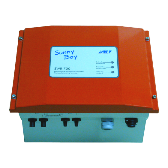
Sunny Boy Technical Description Abbildung 5.1: Partial front view of the SWR 700, SWR 850 identical Signs and symbols for the following text: ⊗ LED is on LED is off LED is blinking State not defined 5.1 Operation Display Switched off during the night ⊗... - Page 45 Sunny Boy Technical Description The SWR 700 resp. SWR 850 is switched off during the night. This operation state is reached when the string voltage at the in- verter is too low for feeding, U < ca. 50 V Operation...
-
Page 46: Failure Display
Sunny Boy Technical Description Manual stop Operation Green LED is blinking Earth fault Failure The SWR 700/850 is in a stop-state chosen by the user, it can be activated via the program Sunny Data. 5.2 Failure Display Mains failure Operation... - Page 47 Sunny Boy Technical Description Before checking the mains fuse disconnect the device on mains side. If the failure remains being displayed although mains power is supplied to the SWR 700/850, the reason for this might be too high mains impedance. This is possible if the lead diameter is too small for the lead length.
- Page 48 • Thermic-monitored varistors Thermic-monitored varistors are installed on DC input side of the SWR 700/850 - Sunny Boy - (plus and minus line each against PE), which have the task to protect - 48 - SWR700-14:EE SMA Regelsysteme GmbH...
- Page 49 Sunny Boy Technical Description the inverter from athmospheric overvoltages (effects of the electric potential of thunderstorm clouds or remote lightning strokes). After thermic-monitored varistors (a thermic-monitored varistor is a series circuit of a varistor and a thermic fuse) have released several times, they may enter a state of high resistance, which disables their protective function.
- Page 50 Fig. 5.2: Thermic-monitored varistors Please note that the thermic-monitored varistors are not available on the market, but are especially designed for the SWR 700/850 - Sunny Boy. The red LED is still lit. Proceed as follows: −...
- Page 51 Sunny Boy Technical Description • If the red LED is still lit, the device is defective and must be repaired by the ma- nufacturer. If the red LED goes out, there is an insulation fault in the PV generator resp. in the connecting lines.
-
Page 52: Technical Data
Input current: depending on the input voltage PVnom ca. 3.1 to 6.2 A The inverter SWR 700 Sunny Boy is able to feed a maximum output power of 700 W to the mains. - 52 - SWR700-14:EE SMA Regelsysteme GmbH... - Page 53 Sunny Boy Technical Description The maximum input current the inverter can receive depends on the respective input voltage. The inverter cannot be damaged in case a solar generator supplies mo- re than the maximum usable input current, if the input voltage remains within the admissible range.
- Page 54 Sunny Boy Technical Description Output values (mains connection) Nominal output power: 700 W, 560 W, 420 W ACnom Working range, mains voltage: 196 - 253 V AC Working range, mains frequency: 49.8 - 50.2 Hz Output current distortion factor: < 3 % (at K <...
- Page 55 Sunny Boy Technical Description Protection type acc. to DIN 40050/IEC 529: IP65 Size and weight Size (W x H x D): ca. 322 x 290 x 180 mm Weight: ca. 18.5 kg Environmental conditions Admissible ambient temperature range: C to +60 Admissible relative air humidity: 0 ..
- Page 56 Sunny Boy Technical Description Fig. 6.2: Efficiency curve and current and voltage form of the SWR 700 Technical alterations and improvements of the device reserved. - 56 - SWR700-14:EE SMA Regelsysteme GmbH...
- Page 57 Version fixed Ue-Trafo 0.34 0.27 0.20 Operation mode Mpp- Mpp- Mpp- installer operation operation operation Recording funct. installer * For proper service condition of the Sunny Boy Upv-Start mut be larger than Upv-Stop. - 57 - SWR700-14:EE SMA Regelsysteme GmbH...
-
Page 58: Swr 850
PVnom ca. 3.7 to 7.3 A The inverter SWR 850 Sunny Boy is able to feed a maximum output power of 850 W to the mains. The maximum input current the inverter can receive depends on the respective input voltage. - Page 59 Sunny Boy Technical Description Fig. 6.3: Input current as a function of input voltage All-pole disconnection device on DC input side Thermic-monitored varistors on DC input side Voltage ripple: < 5 % Earth fault detection: Protection from confusing the poles:...
- Page 60 Sunny Boy Technical Description EMC: EN 50081, part 1 (EN 55014) EN 50082, part 1 Mains retroaction: EN 60555 Test voltage: 1.5 kV Mains supervision: automatic disconnection device according to VDEW Certification Conformity certificate according to VDEW including disconnection device:...
- Page 61 (kWh) operation mode Fig. 6.4: Efficiency curve and current and voltage form of the SWR 850 Technical alterations and improvements of the device reserved. - 61 - SWR700-14:EE SMA Regelsysteme GmbH...
- Page 62 Sunny Boy Technical Description Parameter list Sunny Data gets all parameters when setting the SWR 850. The following table shows the parameter list. Name Unit Range Default values Alteration (for PV input voltage) possible by ... from.. to... 125..250V SMA-SN...
-
Page 63: Sunny Data
(using the power line modem integrated in the SWR 700 resp. SWR 850 and a plug-in modem for the PC) so that no additional data lines are needed (v. fig. 7.1). The PC can be located anywhere because it receives data from any mains socket. -
Page 64: Data Transmission Via Separate Data Line
Sunny Boy Technical Description Fig. 7.1: Data transmission via mains cable 7.2.2 Data Transmission via Separate Data Line In electric grids with strong high-frequency load, e.g. in an industrial environment, it may happen that power line data transmission is not possible due to the strong harmonic distortion. - Page 65 Technical Description 7.2.2.1 Data Line (RS232) If only one SWR 700 resp. SWR 850 is to be connected to a PC, the easiest variant is their direct connection via a RS232 interface. In this case the maximum data line length between the Sunny Boy and the PC is about 12 m.
- Page 66 Technical Description 7.2.2.2 Data Line (RS485) In case several SWR 700 or SWR 850 are to be connected to a PC in an environment with strong harmonic distortion, a RS485 interface with separate data line should be u- sed, which allows a data line length of up to 1200 m.
-
Page 67: Diagnosis And Communication
Sunny Boy Technical Description 7.3 Diagnosis and Communication The communication by means of Sunny Data makes possible the following functions: • Continuous operation data acquisition of all connected string inverters and ap- pertaining PV module groups • Operation state monitoring and failure indication •... -
Page 68: Graphical User Interface Using Ms Windows
Sunny Boy Technical Description 7.4 Graphical User Interface using MS Windows The very comfortable PC program Sunny Data, which works under Windows, offers a fully graphical user interface and all the positive features known from Windows. That's why Sunny Data offers you the comfortable operation you can expect today. -
Page 69: Guaranty Regulations And Liability
Sunny Boy Technical Description 8 Guaranty Regulations and Liability You have purchased a product, which was thoroughly checked before delivering. If your device should be defective or show a malfunction during the guaranty period in spite of it, please contact your distributor or installer. - Page 70 Sunny Boy Technical Description The customer has to grant SMA the necessary time and opportunity to repair the de- fects. Exclusion of Liability Excluded are any guaranty claims and liabilities for direct or consequential damages due − transportation damages, −...
- Page 71 Sunny Boy Technical Description Further or other claims for direct or indirect damages, especially including claims for damages from positive contract violation, are excluded insofar as not otherwise compel- ling stated by law. - 71 - SWR700-14:EE SMA Regelsysteme GmbH...
-
Page 72: Enclosures
Sunny Boy Technical Description 9 Enclosures 9.1 Supplement 1: Certificates for SWR 700 • SMA Conformity Certificate SWR 700 • CE Conformity Certificate SWR 700 • EMC Clearance Certificate SWR 700 - 72 - SWR700-14:EE SMA Regelsysteme GmbH... - Page 73 Sunny Boy Technical Description - 73 - SWR700-14:EE SMA Regelsysteme GmbH...
- Page 74 Sunny Boy Technical Description - 74 - SWR700-14:EE SMA Regelsysteme GmbH...
- Page 75 Sunny Boy Technical Description - 75 - SWR700-14:EE SMA Regelsysteme GmbH...
-
Page 76: Supplement 2: Certificates For Swr 850
Sunny Boy Technical Description 9.2 Supplement 2: Certificates for SWR 850 • SMA Conformity Certificate SWR 850 • CE Conformity Certificate SWR 850 • EMC Clearance Certificate SWR 850 - 76 - SWR700-14:EE SMA Regelsysteme GmbH... - Page 77 Sunny Boy Technical Description - 77 - SWR700-14:EE SMA Regelsysteme GmbH...
- Page 78 Sunny Boy Technical Description - 78 - SWR700-14:EE SMA Regelsysteme GmbH...
- Page 79 Sunny Boy Technical Description - 79 - SWR700-14:EE SMA Regelsysteme GmbH...
-
Page 80: Supplement 3: Boring Jig
Sunny Boy Technical Description 9.3 Supplement 3: Boring jig - 80 - SWR700-14:EE SMA Regelsysteme GmbH...
Need help?
Do you have a question about the SWR 850 and is the answer not in the manual?
Questions and answers