
Related Manuals for Hatz 2-4L41C


Summary of Contents for Hatz 2-4L41C
- Page 1 INSTRUCTION BOOK 2 - 4 L 41 C 2 - 4 M 41. 4 L 42 C 4 M 42 433 416 06-USA-EPA IV-CARB 1.08 - 0.1 Printed in Germany...
- Page 2 Using it in any other manner contravenes the intended purpose. For danger and damage due to this, Motorenfabrik HATZ assumes no liability. The risk is with the user only. Use of this engine in the intended manner presupposes compliance with the maintenance and repair instructions laid down for it.
-
Page 3: Table Of Contents
Contents Page Important notes on safe operation of the engine Description of engine General information 3.1. Technical data 3.2. Transport Installation instructions 3.4. Load on engine 3.5. EPA / CARB - type plates and fuel label 3.6. Emission-related installation instructions Operation 4.1. -
Page 4: Important Notes On Safe Operation Of The Engine
– Rotating parts must be shielded so that they cannot be touched accidentally when the engine is in- stalled in other equipment or machinery. Guards are available from HATZ to protect belt drives for cooling fans and generators. – Before attempting to start the engine it is essential to have studied the starting information in the Instruction Book. - Page 5 – Please pay attention to all advice- and warning stickers placed on the engine and keep them in legi- ble condition. Contact your next HATZ service station, if a sticker comes off or is illegible and ask for a new one.
-
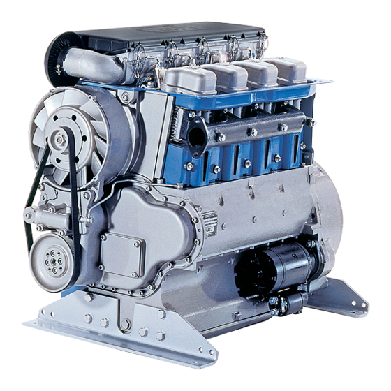
Page 6: Description Of Engine
2. Description of engine Fully encapsulated „Silent Pack“ version Engine 2 ... 4 L 41 C 1 Access cover for fuel delivery pump 12 Air outlet duct 2 Oil filler pipe and dipstick 13 Capsule hood 3 Type plate 14 Suspension lug (retractable), 4 Speed control lever max. - Page 7 Description of engine Fully encapsulated „Silent Pack“ version Engine 4 L 42 C 1 Electronic control unit 14 Suspension lug (retractable), 2 Oil filler pipe and dipstick max. load 5000 N 3 Type plate 15 Air intake duct for capsule 4 Speed control lever 16 Combustion air intake aperture 5 Replaceable-element oil filter...
- Page 8 Description of engine Standard version Engine 2 ... 4 M 41 • 2 ... 4 M 41 Z 1 Oil filler pipe and dipstick 13 Cylinder head cover 2 Side panel 14 Air cleaner cover 3 Combustion air intake aperture 15 Suspension lug, max.
- Page 9 Description of engine Standard version Engine 4 M 42 1 Oil filler pipe and dipstick 14 Air cleaner cover 2 Side panel 15 Suspension lug, max. load 5000 N 3 Combustion air intake aperture 16 Fuel return line 4 Cooling fan drive belt 17 Fuel feed line with fuel pre-filter and 5 Cooling fan with alternator attached manual fuel pump...
-
Page 10: General Information
General information 3.1. Technical data 2 L 41 C 3 L 41 C 4 L 41 C / 4 L 42 C 2 M 41. 3 M 41. 4 M 41. / 4 M 42. Type Air-cooled, four-stroke diesel engine Combustion method Direct fuel injection Number of cylinders... -
Page 11: Transport
You can obtain a copy of this manual from your nearest HATZ ➀ EPA / CARB - Engine Family Number service station. -
Page 12: Emission-Related Installation Instructions
For any offer as well as spare parts orders it is Fuel label necessary to mention the following data (also see spare parts list, page 1): ➁ engine type / spec. (only for special equipment) ➂ engine number ➃ max. engine rated speed LOW SULFUR FUEL OR ULTRA LOW SULFUR FUEL ONLY The layout is identical for constant-speed and... -
Page 13: Operation
Engine oil quantities and dipstick markings Operation dipstick 4.1. Before first start-up Oil content marking Engine type Sump (liter) (Figure 7, Engines are normally delivered without any fuel item 2) or oil. 2 L 41 C, 2 M 41 Z Yes 4.1.1. - Page 14 The engine should be in a horizontal position 4.1.2. Fuel before adding oil or checking the oil level. Stop the engine before refilling the fuel tank. Never refuel near a naked flame or sparks which could start a fire. Don’t smoke.
- Page 15 Models with manual fuel pump Low temperature resistance (On 4L42C and 4M42 engines only) At low temperatures, the viscosity of Diesel fuel increases. This may result in clogging of the fuel system. Thus, winter fuel must be used at out- side temperatures below 0 °C, or petroleum must be added in time.
- Page 16 If possible, disengage the engine from any driven equipment. The auxiliary equipment should always be placed in neutral. 4.2.1. Starting with the electric starter – Battery charge telltale „2“ and oil pressure warning „3“ must light up. – Turn start key to position II (Fig. 14). –...
- Page 17 7). For troubleshooting regarding other flashing codes, please contact immediately your nearest The display light goes out when the engine is HATZ service station. next started. Problems in the exhaust gas recirculation Even with automatic shutdown monitoring the system may impair the engine’s exhaust gas oil level must be checked every 8 –...
-
Page 18: Starting The Engine
(see Chapter 7). If any problems arise, please contact the nearest Proceed as follows: HATZ service point. – Detach the hood of enclosure „13“ (Figures 1 and 2) or side panel „2“ (Figures 3 and 4). 4.2.3. Starting with handle... - Page 19 Important ! 3M41 three-cylinder engines Turn decompression levers only in the direction shown by the arrow. Exception: the lever can be moved back directly from posi- tion „1“ to „0“. Never operate the automatic decom- pression system when the engine is running.
- Page 20 – If the engine backfires during starting because it was not turned over with sufficient force (the engine could even start to run backwards in certain circumstances), release the starting handle immediately and move the speed con- trol lever to the STOP position (Chapt. 4.3.). The starting handle could be driven round by the engine and cause injury.
-
Page 21: Stopping The Engine
– To repeat the starting attempt, wait for the en- gine to cease rotating, reset the automatic de- compression device and turn the starting handle in the correct starting direction again. 4.3. Stopping the engine If the engine is shut down for a short period, or at the end of the working day or shift, keep the key and the starting handel in a safe place, out of reach of un-... -
Page 22: Maintenance
Maintenance The engine must be stopped before any maintenance work is attempted. Comply with legal requirements when handling and disposing of old oil, filters and cleaning materials. Keep the engine’s starting key out of reach of unauthorized persons. Disconnect the negative battery terminal. At the end of the maintenance work, check that all tools have been removed from the engine and all safety guards, covers etc. - Page 23 2 M 41 without oil pan 2 M 41 with oil pan; 3 - 4 M 41 in all cases...
- Page 24 Depending on engine type and version, one of The following work is essential on new or the three self-adhesive maintenance charts illus- reconditioned engines after the first 25 hours trated here and on the previous page will be of operation: supplied.
-
Page 25: Maintenance Every 8 - 15 Hours Of Operation
8 – 15 Maintenance every hours of operation 5.2.1. Check engine oil level When checking the oil level, the engine should be standing level, and must not be running. L3/63 1327/2 L3/47 – Check oil level at the dipstick. Add oil up to the MAX mark on dipstick „1“... - Page 26 On 2-4L41 and 2-4M41 engines only On 4L42C and 4M42 engines only – Increase the engine speed briefly to maximum level and watch out for the pilot lamp „5“ to flash. The following flashing code indicates that maintenance work is required on the air cleaner (Chapter 5.4.2).
-
Page 27: Maintenance Every 250 Hours Of Operation
5.3. Maintenance every hours of operation 5.3.1. Engine oil change (see Chapter 5.1.) The dipstick mark will indicate whether or not the engine has a sump (see Chapter 4.1.1.). The engine must be stopped, and should be standing on a flat, level surface. –... - Page 28 5.3.2. Cleaning cooling fan, cooling fins and oil cooler Before cleaning, the engine must be stopped and allowed to cool down. – On encapsulated engines, unscrew and remove the hood, side panel with speed control lever, cover plate on operating side and air outlet duct and cover plate on air outlet side (see Chapter 2).
- Page 29 – Dry the engine with a compressed air jet. – Trace the cause of any contamination with oil and have the leak eliminated by a HATZ service station. – Install the capsule or air guide elements previously removed.
- Page 30 Note: 5.3.5. Check water trap Do not tighten the cylinder head nuts. On 4L42C and 4M42 engines only) The water trap inspection interval depends The adjusting screws at the engine exclusively on the water contained in the fuel governor and on the injection system and on the care applied in refuelling.
-
Page 31: Maintenance Every 500 Hours Of Operation
Important ! 5.4. Maintenance every hours When installing a new filter, note the arrow indi- of operation cating the correct flow direction (depends on whether the tank is mounted HIGH or LOW. 5.4.1. Replace fuel pre-filter The pre-filter’s installed position (direction of Do not smoke and never bring a naked flow) should be as vertical as possible. - Page 32 5.4.2. Air cleaner maintenance It is best to clean the filter cartridge(two pcs. on four-cylinder engines) only when the mainte- nance indicator displays the appropriate signal. Apart from this, the cartridge should be renewed after 500 hours of operation. Removing the air filter cartridge (on 2..4 L 41.
- Page 33 – Release clips „1“ and take off the cover of air Important cleaner housing „2“ (Figure 46). Air pressure must not exceed 5 bar, and the compressed air jet must be held approx. – Remove dirt adhering in the air cleaner area. 150 mm (6 in) away from the filter cartridge.
- Page 34 Mechanical contamination indicator – Insert a ratchet wrench or a 1/2" T-piece with the necessary extension into square hole „1“ (Figure 50). Important ! Turn the engine over in the normal direction of rotation. This is counter-clockwise in either case – at the flywheel or timing gear end.
- Page 35 Adjusting method for three- and four-cylin- – Attach the cover to the cylinder head again; always use new sealing rings. der engines (Fig. 51) – Do not use the nuts securing the cover to the Valve No..Check valves cylinder head more than twice before renewing Type fully open...
- Page 36 5.4.4. Engine oil change 1000 5.5. Maintenance every hours (see Chapters 5.3.1. and 5.1.) of operation 5.5.1. Renewing the fuel filter 5.4.5. Renewing oil filter Do not smoke and never bring a naked Risk of scalding from hot oil. flame near the fuel system when work- Trap the old oil and dispose of it in an ing on it.
- Page 37 – Install the filter element and screw up Renewing the fuel filter handtight. (On 4L42C and 4M42 engines only) – Open the fuel supply line again. – Close the fuel lines at the filter housing. L3/46 Note: To make starting easier, it is best to prime the fuel delivery pump at lever „1“...
-
Page 38: Operating Checks And Repair Work
Operating checks and repair work 6.1. Checking operation of air cleaner maintenance indicator Every 250 hours of operation, perform a routine check on the maintenance indicator or mainte- nance switch and the display light. – Detach the capsule hood or side trim (see Chapter 2). - Page 39 Mechanical maintenance indicator – Pull hose „2“ off air intake pipe and build up a strong vacuum at the open end (Figure 61). L3/56 – Pull hose „2“ off air intake pipe and build up a strong vacuum at the open end. L3/78 –...
-
Page 40: Renewing Fan Drive Belt, Checking Operation Of Belt Monitor
6.2. Renewing fan drive belt, checking operation of belt monitor L3/65 – Remove the machine screw to release the pis- L3/249 ton with tensioning pulley „1“. – Spring pressure will force the piston with ten- – Remove one machine screw at belt pulley „1“. sioning pulley out of the housing. - Page 41 – Push piston with tensioning pulley „2“ into housing „3“ and lock with the machine screw (Figure 66). L3/70 – Insert a large screwdriver between the hydrau- lic belt tensioner and the belt pulley and press it down until the pulley slides on to the center- L3/68 ing hub.
-
Page 42: Malfunctions - Causes And Remedies
Malfunctions – causes and remedies Kind of trouble Possibly caused by Remedy Chapt. Engine will not Speed control lever is in stop or Move lever to 1/2 START or start or is reluctant idle position. max. START position according to start although it to operating conditions. - Page 43 - battery and / or other cable Check electrical system and its does not turn the connections are not correct. components or contact a HATZ engine over. - loose and / or corroded cable service point. connections.
- Page 44 Renew filter. 5.4.1. blocked. 5.5.1 Fan drive belt is broken. Renew the Poly-V belt. Mechanical defect. Contact a HATZ service point. In addition, if auto- Stop signal from monitoring matic engine shut- element because of: Check engine for: down is installed.
- Page 45 Kind of trouble Possibly caused by Remedy Chapt. Engine power and Air cleaner is blocked. Check degree of air cleaner speed drop, black contamination and renew filter smoke from ex- element if necessary. 5.4.2 haust. Valve clearances incorrect. Adjust valve clearances. 5.4.3.
-
Page 46: Work On The Electrical System
HATZ assumes no liability for electrical systems Do not place any tools on top of the battery. which have not been carried out acc. to HATZ circuit diagrams. Always disconnect the negative (–) terminal of the battery before working on the electrical system. -
Page 48: Supplemental Information To The Owner's Manual For 2008 And Later
SUPPLEMENTAL INFORMATION TO THE OWNER'S MANUAL FOR 2008 AND LATER EPA CERTIFIED NONROAD COMPRESSION IGNITION ENGINES. EPA EMISSION CONTROL SUPPLEMENTAL WARRANTY STATEMENT AND EMISSION-RELATED INSTALLATION INSTRUCTIONS. - Page 49 ENGINE PARTS AND / OR EQUIPMENT RELATED TO EPA EXHAUST EMISSION REGULATIONS. Parts which are mandatory for engine operation. The following parts as manufactured according to HATZ specifications are mandatory for engine operation which meets EPA exhaust emission regulations. • Fuel Injection pump(s) •...
- Page 50 • Solenoids • Wiring harnesses • Fuel hoses • Intake and exhaust gaskets • Emission Control Information Labels Only parts manufactured by Hatz and which have passed the Hatz Quality Assurance Program are assured of meeting EPA exhaust emission regulations.
- Page 51 Normally the equipment manufacturer takes this into account during the design of the machine and your equipment will perform within specifications over a wide range of climatic conditions. However if you must operate your equipment under very unusual climatic conditions, please contact your nearest Hatz distributor for advice.
- Page 52 The exhaust quality of the engines can be influenced by the execution (the quality of execution) of above described maintenance work. Therefore, the maintenance work has to be carried out by a qualified workshop. Hatz authorised workshops, for example, are qualified workshops. Hatz Diesel of America will give you respective addresses, if required.
- Page 53 EMISSION CONTROL SYSTEM AND ADJUSTMENTS. The emission control system for the engine series 2-4L41C and 2-4M41 is EM (Engine Modification). No adjustments are needed or possible. The emission control system for the engine series 4L42C and 4M42 is EM (Engine Mod- ification) and EGR (Exhaust Gas Recirculation).
- Page 54 • Fuel hoses • Intake and exhaust gaskets • Emission Control Information Labels Where a warrantable condition exists, Motorenfabrik Hatz will repair your engine at no cost to you including diagnosis, parts and labor. MANUFACTURERS WARRANTY COVERAGE: The emission control related parts of 2008 and later engines are warranted as follows:...
- Page 55 • As the engine owner, you should be aware, however, that Motorenfabrik Hatz may deny you warranty coverage if your engine or a part has failed due to abuse, neglect, improper maintenance or unapproved modifications.
- Page 56 • Crankcase breather valve assembly • Oil filler cap • Vacuum switch • Electronic control unit (on 4L42C and 4M42 engines) • Oil temperature sensor (on 4L42C and 4M42 engines) • Governor position sensor (on 4L42C and 4M42 engines) • Engine speed sensor (on 4L42C and 4M42 engines) •...
- Page 57 Hatz Diesel of America, Inc. hereinafter referred to as “HATZ” warrants each of the above-listed parts when installed in a new engine sold by Hatz to be free from defects in material and workmanship under normal use and service, only under the named warranty...
- Page 58 EMISSION-RELATED INSTALLATION INSTRUCTIONS “Failing to follow these instructions when installing a certified engine in a piece of nonroad equipment violates federal law (40CFR1068.105(b)), subject to fines or other penalties as described in the Clean Air Act.” “If you install the engine in a way that makes the engine's emission control information labels hard to read during normal engine maintenance, you must place duplicate labels on the equipment.”...
- Page 59 INSTRUCTIONS ON THE INSTALLATION OF THE EXHAUST SYSTEM Following are the instructions to properly install the exhaust system and related components consistent with the EPA emission regulation requirements. 2 - 4 M 41 · 4 M 42 Exhaust-silencers The exhaust silencer is fitted in connection with gaskets. Fixation is done by hexagon head screws 1 and Allen screws 3.
- Page 60 Dismantling: • Remove in numerical sequence 1...5. Assembly: • Assemble in reverse sequence. • Use anti-seize compound J as specified by HATZ.
- Page 61 2 - 4 L 41 C · 4 L 42 C Encapsulated engine Before dismantling the exhaust system the capsule has to be dismounted: • Remove the top cover 1 by opening the clips. • Remove all screws 2 and remove the side cover 3. Assembly: •...
- Page 62 2 - 4 L 41 C · 4 L 42 C...
- Page 63 • Open and remove both nuts 17. • Remove silencer 19 with five identical gaskets 18. Assembly: • Assemble in reverse sequence. • Make sure that all parts are correctly placed and tightened. • Use anti-seize compound J as specified by HATZ.
- Page 64 Specification: Adding a 20-centimeter bended extension to the exhaust pipe Clamp Engine type Ø d (mm) HATZ-Ident. Nr. HATZ-Ident. Nr. 2L41 C 038 775 00 504 103 01 3L41 C...
- Page 66 SUPPLEMENTAL INFORMATION TO THE OWNER’S MANUAL FOR 2008 AND LATER CALIFORNIA REGULATIONS FOR HEAVY-DUTY OFF-ROAD ENGINES CALIFORNIA EMISSION CONTROL WARRANTY STATEMENT AND EMISSION-RELATED INSTALLATION INSTRUCTIONS.
- Page 67 ENGINE PARTS AND / OR EQUIPMENT RELATED TO CARB EXHAUST EMISSION REGULATIONS. Parts which are mandatory for engine operation. The following parts as manufactured according to HATZ specifications are mandatory for engine operation which meets CARB exhaust emission regulations. • Fuel Injection pump(s) •...
- Page 68 • Fuel hoses • Intake and exhaust gaskets • Emission Control Information Labels Only parts manufactured by Hatz and which have passed the Hatz Quality Assurance Program are assured of meeting CARB exhaust emission regulations. UNUSUAL OPERATING CONDITIONS. The engine must not be operated at a load factor less than 25 % for an extended period as such operation will cause the fuel injector to foul.
- Page 69 The exhaust quality of engines can be influenced by the execution (the quality of execution) of above described maintenance work. Therefore, the maintenance work has to be carried out by a qualified workshop. Hatz authorised workshops, for example, are qualified workshops. Hatz Diesel of America will...
- Page 70 EMISSION CONTROL SYSTEM AND ADJUSTMENTS. The emission control system for the engine series 2-4L41C and 2-4M41 is EM (Engine Modification). No adjustments are needed or possible. The emission control system for the engine series 4L42C and 4M42 is EM (Engine Mod- ification) and EGR (Exhaust Gas Recirculation).
- Page 71 • As the heavy-duty off-road engine owner, you are responsible for the performance of the required maintenance listed in your owner’s manual. Motorenfabrik Hatz GmbH & Co. KG recommends that you retain all receipts covering maintenance on your heavy-duty off-road engine, but Motorenfabrik Hatz GmbH & Co.
- Page 72 • EGR valve body (on 4L42C and 4M42 engines) • EGR rate feedback and control system (on 4L42C and 4M42 engines) • Crankcase breather valve assembly • Oil filler cap • Vacuum switch • Electronic control unit (on 4L42C and 4M42 engines) •...
- Page 73 Hatz Diesel of America, Inc. hereinafter referred to as "HATZ" warrants each of the above-listed parts when installed in a new engine sold by Hatz to be free from defects in material and workmanship under normal use and service, for a period of twenty-four (24)
- Page 74 EMISSION-RELATED INSTALLATION INSTRUCTIONS “Failing to follow these instructions when installing a certified engine in a piece of nonroad equipment violates federal law (40CFR1068.105(b)), subject to fines or other penalties as described in the Clean Air Act.” “If you install the engine in a way that makes the engine's emission control information labels hard to read during normal engine maintenance, you must place duplicate labels on the equipment.”...
- Page 75 INSTRUCTIONS ON THE INSTALLATION OF THE EXHAUST SYSTEM Following are the instructions to properly install the exhaust system and related components consistent with the EPA emission regulation requirements. 2 - 4 M 41 · 4 M 42 Exhaust-silencers The exhaust silencer is fitted in connection with gaskets. Fixation is done by hexagon head screws 1 and Allen screws 3.
- Page 76 Dismantling: • Remove in numerical sequence 1...5. Assembly: • Assemble in reverse sequence. • Use anti-seize compound J as specified by HATZ.
- Page 77 2 - 4 L 41 C · 4 L 42 C Encapsulated engine Before dismantling the exhaust system the capsule has to be dismounted: • Remove the top cover 1 by opening the clips. • Remove all screws 2 and remove the side cover 3. Assembly: •...
- Page 78 2 - 4 L 41 C · 4 L 42 C...
- Page 79 • Open and remove both nuts 17. • Remove silencer 19 with five identical gaskets 18. Assembly: • Assemble in reverse sequence. • Make sure that all parts are correctly placed and tightened. • Use anti-seize compound J as specified by HATZ.
- Page 80 Specification: Adding a 20-centimeter bended extension to the exhaust pipe Clamp Engine type Ø d (mm) HATZ-Ident. Nr. HATZ-Ident. Nr. 2L41 C 038 775 00 504 103 01 3L41 C...
- Page 81 CALIFORNIA Proposition 65 Warning Diesel engine exhaust and some of its constituents are known to the State of California to cause cancer, birth defects, and other reproductive harm.
Need help?
Do you have a question about the 2-4L41C and is the answer not in the manual?
Questions and answers