
Related Manuals for Level GB 060 3xx

Summary of Contents for Level GB 060 3xx
- Page 1 GB 060 3xx, GB 060 5xx Programmable GSM Automaton Universal GSM Communicator Installation and User Guide LEVEL...
- Page 3 For that reason it is advisable to have the device installed and set to work by a person or company competent in this field. LEVEL Ltd.
-
Page 4: Table Of Contents
Table of Contents: 1. Model range, safety, accessories ....................5 1.1. GB 060 Models........................5 1.2. Safety Instructions........................5 1.3. Configuration of the GB 060....................6 2. GB 060 Instalation, Functional Description..................7 2.1. GB 060 - connectors .......................7 2.2. Functional Description......................8 2.2.1. Power Sources........................8 2.2.2. -
Page 5: Model Range, Safety, Accessories
(and, consequently, the GB 060) is permitted in your type of car. Installing the GB 060 in places with an increased level of electromagnetic radiation is not advisable as the reliability of the devise can be... -
Page 6: Configuration Of The Gb 060
1.3. Configuration of the GB 060 Code Description of components ● ● ● ● ● ● GB 060 xxx The GB 060 model ● ● ● ● ○ ○ ED 001 001 GSM antenna (3dB) ○ ○ ○ ○ ● ●... -
Page 7: Gb 060 Instalation, Functional Description
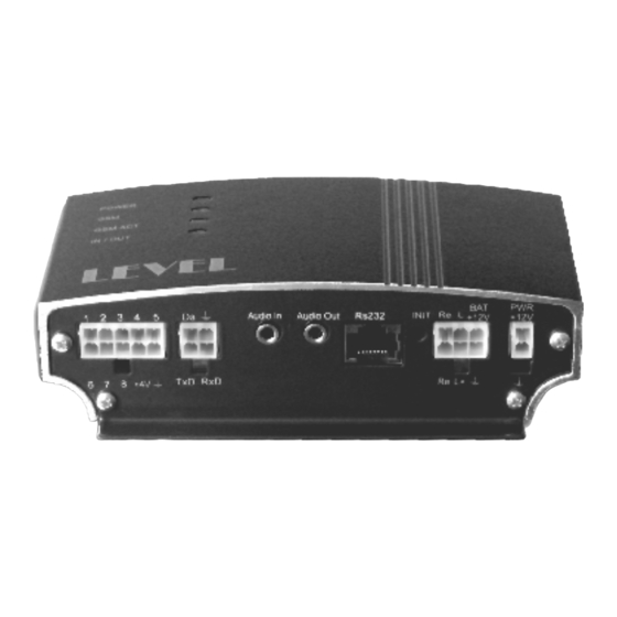
2. GB 060 Instalation, Functional Description 2.1. GB 060 - connectors... -
Page 8: Functional Description
2.2. Functional Description 2.2.1. Power Sources Nominal Voltage 12 V DC (Max. 25 V), Current Max. 0,5 A Power to the GB 060 unit can using either standard AC/DC adapter SA 012 503 or the 12 V power source from vehicle. Power source must be connected to the 2-pin power... -
Page 9: Relay Output
– Bias 3,3 V / 115 kΩ • A not connected input is on high level (H). • Output is protected from overcurrent by electronic retracting safety-fuse. • The +4V clip is intended for power supply of a possible front-end logic. Maximum load is 150 mA. -
Page 10: Dallas Bus
• blinks quickly action in progress – waiting for finishing action • LED on for 1 sec action finished • blinks twice per 1 sec key signing off action in progress • LED permanently on a phone call or a data call in progress 2.2.5. -
Page 11: Id Keys
External unit of analogue inputs ED 060 200 contains for inputs – 2 current loops 4-20 mA and 2 voltage loops 0-10 V that enable to connect different kinds of sensors, for example barometers, humidity meters, water-level indicator etc. Maximum number of connected analogue inputs and thermometers is 10 while 1 external unit = 4 analogue inputs). -
Page 12: Gps Antenna Ed 002 002
Used: 2,3,5,7,8, Connected: 1,4,6 2.2.7. GPS Antenna ED 002 002 GPS antenna ED 002 002 that comes with a 3 meter-long cable gets connected into the SMB coaxial GPS connector. Its location must be in horizontal position with direct view of the sky. GSM signal passes through plastic materials and glass but not through metals and mirror glass. -
Page 13: Sim Card
GB 060 includes GSM module which enables two-way connection in the 900/1800 MHz band into a selected GSM network after the log-in procedure of a SIM card inserted. It is used mainly for: • transmitting alert or informational messages and calls from the GB 060 unit •... -
Page 14: Setting Into Operation And Control
Blinking 0,6 s / 0,6 s GSM module is just logging in • Blinking 0,7 s / 3 s GSM module is logged and works correctly • Permanently ON indication data connection or call in progress • GSM ACT GSM module at rest (no communication takes place) •... -
Page 15: Control
3.3. Control Control of GB 060 – internal configuration settings, switching outputs, reading inputs statuses and internal variables of device can be done using the following options: • Using the GB 060 Control Panel software • Via cable in local connection to serial port in PC •... -
Page 16: Control And Configuration Using The Sms Messages
GPRS Data Connection Using the TCP Protocol To use this connection, the access to relevant proxy server must be provided. Action in GB 060 will launch a call to selected number from phone directory that represents the required GPRS connection. GB 060 will connect to the internet and make the required connection. - Page 17 Basic Command SMS PIN - GB 060 access PIN pin PIN x x=? - query, x=new PIN – change PIN SW, HW version, GB 060 serial number pin PRODUCT Communication adapter SW, HW version, serial number (if installed) pin ADAPTER Power supply status, internal battery, charging pin POWER GB 060 reset...
- Page 18 SMS commands for GPS Abbreviations: jgpsb= GPS point name, jgpst= GPS trace name Position query pin GPS Example of reply: GPS 50 25.220300 N 16 10.078100 E = 50° 25,2203' north 16° 10,0781' east Position query - decimal reply pin GPSD Example of reply: GPSD 50.420261 N 16.167929 E = 50,420261°...
- Page 19 SMS command for actions Launching an action pin action_name Reply: action_name.run Enabling action pin action_name.ENABLE x x=? - query, x=0 - disabled, x=1 - enabled Adding an action into group pin action_name.GROUP x x=? - query, x=0 - group 1 ... x=7 - group 8 SMS commands for analogue inputs Query on list and statuses of all analogue inputs pin AINS...
-
Page 20: Sw Supplied With Gb 060
4. SW Supplied with GB 060 4.1. The GB 060 Control Panel Program Part of the GB 060 software installation is the GB 060 Control Panel software, which serves as a primary tool for the device configuration and for detection of the device's operational state including the state of all its inputs. -
Page 21: Warranty Conditions
Otherwise the user will be offered an alternative solution until the repair is completed. Warranty repairs shall be carried out in the LEVEL company and the warranty period will be extended accordingly. The manner of repair shall solely be decided by the service engineer. -
Page 22: Warranty Certificate
WARRANTY CERTIFICATE Product Name: Model: Serial Number: Date of Sale: Signature: Selling Organization: Address, Telephone, Stamp: Received for Shipment Fault Description Repair Date... - Page 24 © GB 060@1.00 LEVEL, 2005 LEVEL Ltd., Plhovská 1997, Náchod 547 01, CZECH REPUBLIC E-mail: level@levelna.cz www.levelna.cz...
Need help?
Do you have a question about the GB 060 3xx and is the answer not in the manual?
Questions and answers