Table of Contents
Advertisement
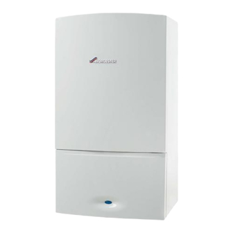
24CDi/28CDi/35CDi II
WALL MOUNTED COMBINATION BOILER FOR CENTRAL HEATING
AND MAINS FED DOMESTIC HOT WATER
INSTALLATION AND
SERVICING INSTRUCTIONS
GC NUMBER (N.G)
GC NUMBER (L.P.G.)
24CDi
28CDi
35CDi II
IMPORTANT: THESE INSTRUCTIONS APPLY IN THE UK ONLY
THESE INSTRUCTIONS ARE TO BE LEFT WITH THE USER OR AT THE GAS METER
This appliance must be installed by a competent person in accordance
with the Gas Safety (Installation and Use) Regulations 1998
RSF
24CDi
47 311 30
47 311 31
BOILER OUTPUT
Automatic Modulating Control
Domestic
Hot Water
9 - 24kW
9 - 28kW
9.5 - 35.3kW
28CDi
35CDi II
47 311 34
47 311 58
47 311 35
47 311 59
Central
Heating
9 - 24kW
9 - 24kW
10.5 - 27.5kW
Advertisement
Table of Contents


Need help?
Do you have a question about the 24CDi and is the answer not in the manual?
Questions and answers
How do I remove the water temperature knob to see why it just spins around when I try to adjust the temp.
To remove the water temperature knob on a Worcester 24CDi, ensure you are following the servicing procedure. The document states that when replacing the control knobs, the knob with the shortest shaft should be fitted to the left-hand control position. However, it does not provide specific steps on removing the knob. Typically, knobs on such boilers can be pulled off or may have a securing screw underneath that needs to be loosened. If unsure, refer to the boiler manual or consult a qualified professional.
This answer is automatically generated