Table of Contents
Advertisement
Quick Links
Advertisement
Table of Contents
Troubleshooting

Related Manuals for Orban Optimod-AM 9400


Summary of Contents for Orban Optimod-AM 9400
- Page 1 Operating Manual OPTIMOD-AM 9400 Digital Audio Processor Version 1.2 Software...
- Page 2 European Parliament, this product must not be discarded into the municipal waste stream in any of the Member States. This product may be sent back to your Orban dealer at end of life where it will be reused or recycled at no cost to you.
-
Page 3: Important Safety Instructions
IMPORTANT SAFETY INSTRUCTIONS All the safety and operating instructions should be read before the appliance is operated. Retain Instructions: The safety and operation instructions should be retained for future reference. Heed Warnings: All warnings on the appliance and in the operating instructions should be adhered to. Follow Instructions: All operation and user instructions should be followed. - Page 4 Safety Instructions (German) Gerät nur an der am Leistungsschild vermerkten Spannung und Stromart betreiben. Sicherungen nur durch solche, gleicher Stromstärke und gleichen AbschalAMerhaltens ersetzen. Sicherungen nie überbrücken. Jedwede Beschädigung des Netzkabels vermeiden. Netzkabel nicht knicken oder quetschen. Beim Abziehen des Netzkabels den Stecker und nicht das Kabel enfassen.
- Page 5 (2) Check the other sections of the Manual (consult the Table of Contents and Index) to see if there might be some sug- gestions regarding your problem. (3) After reading the section on Factory Assistance, you may call Orban Customer Service for advice during normal Cali- fornia business hours. The number is (1) 510 / 351-3500.
- Page 6 All trademarks are property of their respective companies. This manual is part number 96129.120.03 The manual published April 2009 © Copyright Orban 8350 East Evans Suite C4, Scottsdale, AZ 85260 USA Phone: (1) (480) 403-8300; Fax: (1) (480) 403-8301; E-Mail: custserv@orban.com; Site: www.orban.com...
- Page 7 Operating Manual OPTIMOD-AM 9400 Digital Audio Processor Version 1.2 Software...
-
Page 8: Table Of Contents
Table of Contents Index.........................0-9 Section Introduction ............................1-1 .......................1-1 BOUT THIS ANUAL OPTIMOD-AM 9400 D ............1-1 IGITAL UDIO ROCESSOR Making the Most of the AM Channel..............1-2 Controllable and Adjustable...................1-3 Versatile Installation....................1-4 OPTIMOD-AM....................1-5 RESETS IN Factory Presets ......................1-5 User Presets ......................1-6 ..................1-7... - Page 9 9400 F .......................2-12 RONT ANEL ) ............2-13 TUDIO EVEL ONTROLLER NSTALLATION OPTIONAL If you are using Orban 8200ST external AGC ............2-14 Figure 2-7: 8200ST Jumper Settings (*Factory Configuration) ........2-15 .........................2-16 UICK ETUP I/O S ..................2-23 NALOG AND IGITAL ETUP Figure 2-8: Effect of the LPF Shape Control with F = 5.0 kHz........
- Page 10 9400 PC R ............2-51 NSTALLING EMOTE ONTROL OFTWARE Installing the Necessary Windows Services............2-52 Check Hardware Requirements................2-52 Running the Orban Installer Program ..............2-53 Setting Up Ethernet, LAN, and VPN Connections ..........2-54 Conclusion......................2-54 ............2-55 YNCHRONIZING PTIMOD TO A ETWORK ERVER Table 2-1: NIST-referenced timeservers................. 2-55 .............2-59...
- Page 11 Gain Reduction Metering ..................3-17 To Create or Save a User Preset ................3-17 ...................3-18 ACTORY ROGRAMMING RESETS To import an HD preset from the 9400’s front panel: ..........3-20 To import an HD preset from PC Remote:..............3-20 Description of the Analog AM Factory Presets ............. 3-21 Table 3-1: Analog AM Factory Programming Presets ...........
- Page 12 About Aliases created by Optimod 9400 PC Remote Software ......3-67 Multiple Installations of Optimod 9400 PC Remote ...........3-67 To share an archived User Preset between 9400s:............3-69 Section Maintenance ............................4-1 ....................4-1 OUTINE AINTENANCE ...............4-2 UBASSEMBLY EMOVAL AND EPLACEMENT ..................4-6 IELD UDIT OF ERFORMANCE Table 4-1: Decoder Chart for Power Supervisor .............
- Page 13 ........................6-1 PECIFICATIONS Performance......................6-1 Installation .......................6-2 ......................6-4 IRCUIT ESCRIPTION Overview ........................6-5 Control Circuits ......................6-5 User Control Interface and LCD Display Circuits ...........6-6 Input Circuits......................6-7 Output Circuits......................6-9 DSP Circuit......................6-10 Power Supply ......................6-11 ......................6-11 BBREVIATIONS ........................6-13 ARTS Obtaining Spare Parts ...................6-13 Base Board ......................6-14 CPU Module ......................6-15 RS-232 Board......................6-17 Power Supply ......................6-17...
- Page 14 Power Supply ±15V analog supply; ±5V analog Parts Locator 6-43 supply; +5V digital supply Drawing Schematic 1 of 1 6-44 I/O Board Analog Input/Output Parts Locator 6-45 AES3 Input/Output Drawing Composite Output SCA Input. Contains: L and R Analog Inputs Schematic 1 of 5 6-46 L and R Analog Outputs...
-
Page 15: Index
Index analog output circuit description 6- · 9 compensating for 600 ohm load 2- · 28 analog output 2- · 9 8200ST 2- · 14 antenna system 1- · 19 anti-aliased 3- · 44 archiving presets 3- · 64 artifacts minimizing codec 3- ·... - Page 16 bounce 1- · 15 Compressor look-ahead buttons and bass clipper mode 3- · 43 computer escape 2- · 12, 1 modify 2- · 12, 1 connecting to 2- · 4 next 2- · 12, 1 interface, specifications 6- · 3 previous 2- ·...
- Page 17 display assembly Firmware removing 4 · 2 updating 9400 2- · 81 display board five-band parts list 6- · 25 attack time controls 3- · 52 replacing 4 · 5 band coupling controls 3- · 51 distortion band on/off switch 3- · 52 band threshold control 3- ·...
- Page 18 circuit 2- · 11 installation procedure 2- · 1 loss of 4- · 1 Instrumental format 3- · 26 power 2- · 11 Internet grounding 2- · 11 cannot access 5- · 8 grouping 9400s 3- · 66 IP address 2- · 48 IP port 2- ·...
- Page 19 Defined 3- · 3 Monitor Rolloff Filter 1- · 23 lossy data reduction monitor rolloff filter 2- · 5 in studio 1- · 19 multiband drive 3- · 46 NICAM 1- · 12 multiband limit threshold 3- · 50 used in STLs · 11 multiband llimiter drive 3- ·...
- Page 20 Impact 3- · 26 recovering from lost 2- · 45 Instrumental 3- · 26 Jazz 3- · 26 Orban installer program 2- · 53 Loud 3- · 26 PC board locator diagram 6- · 29 News-Talk 3- · 27 Rock 3- · 27 PC control Sports 3- ·...
- Page 21 PC Remote software 3- · 61 serial connector 2- · 8 remote control service 5- · 14 bypass 1- · 25 Set clock connecting 2- · 3 via GPI 2- · 47 GPI, specifications 6- · 4 setup wiring 2- · 4 I/O 2- ·...
- Page 22 creating 3- · 6, 15, 17 System Setup screen 2- · 16 user presets 1- · 6 talk 3- · 48 voltage select switch 2- · 2, 7 Talk format 3- · 27 volume TCP/IP balancing AM and HD channel 2- · 39 setting parameters 2- ·...
-
Page 23: Section 1 Introduction
Because OPTIMOD-AM incorporates several audio processing innovations exclusive to Orban products, you should not assume that it can be operated in the same way as less sophisticated processors. If you do, you may get... -
Page 24: Making The Most Of The Am Channel
AM mud, it is very important that the source audio be as clean as possible. Orban's publication Maintaining Audio Quality in the Broadcast Facility (available in .pdf form from ftp.orban.com) contains valuable information and specific suggestions for... -
Page 25: Controllable And Adjustable
This output can also be used for netcasts. Orban’s PreCode™ technology manipulates several aspects of the audio to minimize artifacts caused by low bitrate codecs, ensuring consistent loudness and texture from one source to the next. There are several HD factory presets tuned specifically for low bitrate codecs. -
Page 26: Versatile Installation
INTRODUCTION ORBAN MODEL 9400 through the 9400’s Ethernet port or serial port (connected to an external mo- dem), or locally (by connecting a Windows® computer to the 9400’s serial port through the supplied null modem cable). The 9400 can be remote-controlled by 5-12V pulses applied to eight pro- grammable, optically isolated “general-purpose interface”... -
Page 27: Presets In Optimod-Am
All input, output, and power connections are rigorously RFI-suppressed to Orban’s traditional exacting standards, ensuring trouble-free installation. The 9400 is designed and certified to meet all applicable international safety and emissions standards. -
Page 28: User Presets
INTRODUCTION ORBAN MODEL 9400 There are two sets of presets: one for the analog AM processing and one for the digital radio processing (HD). The preset for the analog AM processing is the master preset. In addition to parameters specific to the AM analog processing, it contains the AGC and stereo enhancer parameters, which are common to both the AM ana- log and digital radio processing chains. -
Page 29: Input/Output Configuration
OPTIMOD-AM DIGITAL INTRODUCTION Input/Output Configuration OPTIMOD-AM simultaneously accommodates: Digital AES3 left/right inputs and outputs. Analog left/right inputs and outputs. Digital AES3 Left/Right Input/Outputs The digital inputs and outputs conform to the professional AES3 standard. They both have sample rate converters to allow operation at 32, 44.1, 48, 88.2, and 96 kHz sample frequency. -
Page 30: Remote Control Interface
INTRODUCTION ORBAN MODEL 9400 The two left and right analog output pairs are on XLR-type male connectors on the rear panel. Output impedance is 50; balanced and floating. The outputs can drive 600 or higher impedances, balanced or unbalanced. The peak output level is ad- justable from –6dBu to +20dBu. - Page 31 OPTIMOD-AM DIGITAL INTRODUCTION with non-constant group delay and/or non-flat frequency response in the 30-9500Hz range. Deviation from flatness and phase-linearity will cause spurious modulation peaks because the shape of the peak-limited waveform is changed. Such peaks add nothing to average modulation. Thus, the average modulation must be lowered to accommodate those peaks so that they do not overmodulate.
-
Page 32: Best Location For Optimod-Am
1-10 INTRODUCTION ORBAN MODEL 9400 Best Location for OPTIMOD-AM The best location for OPTIMOD-AM is as close as possible to the transmitter so that its output can be connected to the transmitter through a circuit path that introduces the least possible change in the shape of OPTIMOD-AM’s carefully peak-limited waveform. -
Page 33: Studio-Transmitter Link
1-11 OPTIMOD-AM DIGITAL INTRODUCTION Studio-Transmitter Link Transmission from Studio to Transmitter There are several types of studio-transmitter links (STLs) in common use in broadcast ® service: uncompressed digital, digital with lossy compression (like MPEG, Dolby , or ® APT-x ), microwave, analog landline (telephone / post line), and audio subcarrier on a video microwave STL. -
Page 34: Dual Microwave Stls
The signal-to-noise ratio of the STL can be used optimally if an Orban Optimod-PC 1101, Optimod 6300, 8200ST Compressor / Limiter / HF Limiter / Clipper or an 4000 Transmission Limiter protects the link from overload. -
Page 35: Analog Landline (Ptt / Post Office Line)
Nevertheless, in a dual-microwave system, the 9400 is usually located at the main AM transmitter and is driven by the microwave receivers. One of Orban’s studio level control systems, such as the 8200ST, protects the microwave transmitters at the stu- dio from overload. -
Page 36: Bypassing The Transmitter's Internal Filters And Clippers
1-14 INTRODUCTION ORBAN MODEL 9400 station is highly dependent upon the high-power sections of the transmitter, and upon the behavior of the antenna system. The extremely high average power and the pre-emphasized high-frequency compo- nent of audio processed by OPTIMOD-AM put great demands upon the performance of the transmitter and antenna system. -
Page 37: Power Supplies
1-15 OPTIMOD-AM DIGITAL INTRODUCTION limits on occupied bandwidth specified by the governing authority and will greatly degrade the spectral control provided by OPTIMOD-AM. To achieve the full performance capability built into OPTIMOD-AM, any filters in the transmitter must be bypassed. This is essential! OPTIMOD-AM contains low-pass and high-pass filters that are fully capable of protecting the transmitter and controlling occupied bandwidth. -
Page 38: Pre-1965 Transmitters
1-16 INTRODUCTION ORBAN MODEL 9400 The newer generations of transmitters employ switching modulation techniques to control bounce far better than do older plate-modulated designs. The latest trans- mitters using digital modulation techniques have even better performance and most are essentially transparent. -
Page 39: Transmission Presets And Transmitter Equalization
1-17 OPTIMOD-AM DIGITAL INTRODUCTION creases loudness and brightness, and will produce dense positive peaks up to 125% if this is desired. However, such asymmetrical processing by its very nature produces both odd and even-order harmonic and IM distortion. While even-order harmonic distortion may sound pleasingly bright, IM distortion of any order sounds nasty. - Page 40 1-18 INTRODUCTION ORBAN MODEL 9400 HF Shelf Breakpoint Frequency for L+R [L+R HF FR] HF Shelf Breakpoint Frequency for L–R [L–R HF FR] HF Delay equalization for L+R [L+R HF ] HF Delay equalization for L–R [L–R HF ] Transmission Presets also contain the following controls: ...
-
Page 41: Antenna System
1-19 OPTIMOD-AM DIGITAL INTRODUCTION Antenna System AM antenna systems, whether directional or non-directional, frequently exhibit in- adequate bandwidth or asymmetrical impedance. Often, a system will exhibit both problems simultaneously. An antenna with inadequate bandwidth couples RF energy into space with progres- sively less efficiency at higher sideband frequencies (corresponding to higher modu- lation frequencies). -
Page 42: About Transmission Levels And Metering
1-20 INTRODUCTION ORBAN MODEL 9400 may be perceived as distortion, “gurgling,” or other interference. Psychoacoustic calculations are used to ensure that the added noise is masked by the desired pro- gram material and not heard. Cascading several stages of such processing can raise the added quantization noise above the threshold of masking into audibility. -
Page 43: Studio Line-Up Levels And Headroom
1-21 OPTIMOD-AM DIGITAL INTRODUCTION Studio Line-up Levels and Headroom The studio engineer is primarily concerned with calibrating the equipment to pro- vide the required input level for proper operation of each device, and so that all de- vices operate with the same input and output levels. This facilitates patching devices in and out without recalibration. -
Page 44: Line-Up Facilities
1-22 INTRODUCTION ORBAN MODEL 9400 to prevent overloading or overmodulation of the transmission system. This peak overload level is defined differently, system to system. In FM modulation, it is the maximum-permitted RF carrier frequency deviation. In AM modulation, it is negative carrier pinch-off. In analog telephone / post / PTT transmission, it is the level above which serious crosstalk into other channels occurs, or the level at which the amplifiers in the channel overload. -
Page 45: Monitoring
Rolloff filtering can be used to supply moni- tors with audio that more closely resembles that heard over a typical receiver. Orban offers the optional model MRF-023 Monitor Rolloff Filter for this purpose. This filter is a small passive unit designed to be installed between the modulation... -
Page 46: Headphones
1-24 INTRODUCTION ORBAN MODEL 9400 two filters. (See step 8 on page 2-5 for installation instructions). The filter provides complementary de-emphasis and a 10 kHz notch for off-air monitoring of NRSC standard audio. The output of the rolloff filter accurately simulates the sound of a standard NRSC receiver. -
Page 47: Pc Control And Security Passcode
1-25 OPTIMOD-AM DIGITAL INTRODUCTION 3. Program any two Remote Interface inputs for “Bypass” and “Exit Test,” respectively. Then place the 9400 in Bypass mode by remote control. A) Connect two outputs from your station remote control system to the REMOTE INTERFACE connector on the rear panel of the 9400, according to the wiring diagram in Figure 2-2 on page 2-4. -
Page 48: Why The North American Nrsc Standard
This cutting of the bandwidth had the effect of reducing the receiver's high-frequency response, but it was felt that lower fidelity would be less obnoxious than interference. As long ago as 1978, Orban proposed and imple- mented pre-emphasis and low-pass filtering for AM broadcast to provide brighter sound at the receiver while minimizing interference. -
Page 49: Nrsc Standard Pre-Emphasis And Low-Pass Filtering
1-27 OPTIMOD-AM DIGITAL INTRODUCTION receivers would be deprived of much high-end energy and would sound both qui- eter and duller. In response to this dilemma, the National Radio Systems Committee (NRSC) under- took the difficult task of defining a voluntary recommended pre-emphasis curve for AM radio that would be acceptable to broadcasters (who want the highest quality sound on the majority of their listeners' radios) and to receiver manufacturers (who are primarily concerned with interference from first- and second-adjacent stations). -
Page 50: Warranty, User Feedback
However, the limitation of any right or remedy shall not be effective where such is prohibited or restricted by law. Simply take or ship your Orban products prepaid to our service department. Be sure to include a copy of your sales slip as proof of purchase date. We will not repair transit damage under the no-charge terms of this warranty. -
Page 51: Extended Warranty
Warranty (yielding a total Warranty period of five years) by remitting to Orban ten percent of the gross purchase price of your Orban product. This offer applies only to new Orban products purchased from an authorized Orban Dealer. -
Page 53: Section 2 Installation
Complete the Registration Card and return it to Orban. (please) The Registration Card enables us to inform you of new applications, per- formance improvements, software updates, and service aids that may be... - Page 54 INSTALLATION ORBAN MODEL 9400 2. Check the line voltage, fuse and power cord. DO NOT connect power to the unit yet! A) Check the V switch. This is on the rear panel. OLTAGE ELECT The 9400 is shipped from the factory with the V...
- Page 55 OPTIMOD-AM DIGITAL INSTALLATION 3. Set Ground Lift switch. The G switch is located on the rear panel. ROUND The G switch is shipped from the factory in the GROUND position, (to ROUND connect the 9400’s circuit ground to its chassis ground). This is almost always op- timum.
- Page 56 INSTALLATION ORBAN MODEL 9400 PIN ASSIGNMENT DIGITAL GOUND REMOTE REMOTE REMOTE REMOTE REMOTE REMOTE REMOTE INTERFACE REMOTE REMOTE TALLY TALLY ANALOG GROUND REMOTE REMOTE REMOTE REMOTE REMOTE REMOTE REMOTE REMOTE 22-24. N/C +12 VOLTS DC Figure 2-2: Wiring the 25-pin Remote Interface Connector 7.
- Page 57 INSTALLATION 8. Install Monitor Rolloff Filter. (optional) Orban Monitor Rolloff Filters are accessories that can be ordered from your au- thorized Orban Broadcast Dealer. The Orban model number is MRF-023. The Orban Monitor Rolloff Filter alters the flat response typical of a modulation monitor's audio output to one that more closely resembles that of an actual AM receiver.
-
Page 58: Olloff
INSTALLATION ORBAN MODEL 9400 OPTIMOD-AM. The amount of rolloff is adjustable with the filter's high frequency ROLLOFF control to complement the setting of the HF G control on OPTIMOD-AM. B) Change the jumpers to the desired rolloff. See Figure 2-4 on page 2-5. -
Page 59: 9400 Rear Panel
OPTIMOD-AM DIGITAL INSTALLATION E) Connect the earth ground terminals on the Rolloff Filter to earth ground for shielding. To avoid potential ground loops, the earth ground is not connected to the COM terminals. F) Set the R control of the Rolloff Filter to taste. See Figure 2-5 on page 2- OLLOFF Figure 2-6: Monitor Rolloff Filter Schematic Diagram 9400 Rear Panel... -
Page 60: Input And Output Connections
INSTALLATION ORBAN MODEL 9400 An RS-232 (PC Remote) Computer Interface, labeled S , is provided to ERIAL connect the 9400 to IBM PC-compatible computers, directly or via modem, for re- mote control, metering and software downloads. A Remote Interface Connector allows you to connect the 9400 to your existing transmitter remote control or other simple contact-closure control devices. -
Page 61: Analog Audio Input
OPTIMOD-AM DIGITAL INSTALLATION Analog Audio Input IMPORTANT: Because the 9400’s music/speech detector uses information about the stereo sound field to make its detection more accurate, it is important to feed the 9400 with stereo source material even if it is only being used to drive a monophonic AM analog transmitter. -
Page 62: Aes3 Digital Input And Output
2-10 INSTALLATION ORBAN MODEL 9400 range. Loading the output with 600 will decrease the output level by 4.0 dB compared to a high impedance (bridging) load and will reduce the maximum available output level by 4.0 dB. A software switch in Analog Output screen al- lows the output level calibration to be set for a bridging or 600... -
Page 63: Grounding
2-11 OPTIMOD-AM DIGITAL INSTALLATION link with bit-for-bit transparency. Because sample rate conversion is a phase-linear process that does not add bandwidth, the 9400’s output sig- nal will continue to be compatible with 32 kHz links even if it undergoes intermediate sample rate conversions (for example, 32 kHz to 48 kHz to 32 kHz). -
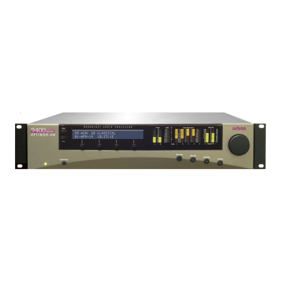
Page 64: 9400 Front Panel
2-12 INSTALLATION ORBAN MODEL 9400 ground by a wide copper strap — wire is ineffective at RF frequencies because of the wire’s self-inductance. 9400 Front Panel Screen Display labels the four soft buttons and provides control-setting infor- mation. ... -
Page 65: Studio Level Controller Installation (Optional)
Continue with “Quick Setup” on page 2-16.] As of this writing, the currently manufactured Orban products that can be used as external AGCs are Optimod-PC 1101 and Optimod 6300. Their manuals con- tain instructions on how to use them in this application. They are the preferred choices because their AGCs are identical to the AGC in the 8500. -
Page 66: If You Are Using Orban 8200St External Agc
2-14 INSTALLATION ORBAN MODEL 9400 If you are using Orban 8200ST external AGC If the STL uses pre-emphasis, its input pre-emphasis network will probably introduce overshoots that will increase peak modulation without any increase in average modulation. We therefore strongly recommend that the STL transmitter’s pre- emphasis be defeated (freeing the STL from such potential overshoot), and that the 8200ST be used to provide the necessary pre-emphasis. - Page 67 2-15 OPTIMOD-AM DIGITAL INSTALLATION TOP OF MAIN BOARD Clipper Jumpers Output Pre-Emphasis Jumpers FLAT PRE-EMPHASIZED CLIPPER ON CLIPPER OFF LEFT RIGHT LEFT RIGHT OUTPUT OUTPUT OUTPUT OUTPUT Line-up Level Jumpers *PEAK LEFT RIGHT LEFT RIGHT OUTPUT OUTPUT OUTPUT OUTPUT Figure 2-7: 8200ST Jumper Settings (*Factory Configuration)
-
Page 68: Quick Setup
2-16 INSTALLATION ORBAN MODEL 9400 C) Turn off the tone by pressing the T button. If the STL transmitter suffers from bounce or overshoot, you may have to reduce the control settings to avoid peak overmodulation caused by overshoots on certain audio signals. - Page 69 2-17 OPTIMOD-AM DIGITAL INSTALLATION For the following adjustments, use the appropriately labeled soft button to choose the parameter you wish to adjust. To change a parameter (like an output level), you must usually hold down the soft button while turning the knob. However, if there is only one parameter on a screen, you can change this with the knob alone.
- Page 70 2-18 INSTALLATION ORBAN MODEL 9400 5. Set output bandwidth. This step sets the lowpass filter bandwidth in the default transmission preset (TX1/DAY). A) Press the N button. B) Select the lowpass filter cutoff frequency you need by turning the knob.
- Page 71 9400 AGC status to be determined by the selected preset. If you are using an Orban 4000 Transmission Limiter, set field to N that the AGC function in the 9400 continues to work). The Orban 4000 is a transmission system overload protection device and is normally oper- ated below threshold.
- Page 72 2-20 INSTALLATION ORBAN MODEL 9400 Note that Quick Setup does not contain full instructions for setting up a CQUAM system. Please refer to the detailed instructions following Quick Setup. If you are operating your analog transmitter in mono, choose either...
- Page 73 2-21 OPTIMOD-AM DIGITAL INSTALLATION Turn the knob to set the Digital O to 32, 44.1, 48, 88.2, UTPUT AMPLE or 96 kHz. This control sets the sample rate of Digital Output #1, which is the output most likely to be used to drive your transmitter. The internal sample rate converter sets the rate at the 9400’s digital out- puts.
- Page 74 2-22 INSTALLATION ORBAN MODEL 9400 14. Set the analog output level. A) Press the N button. B) [Skip this step if you are not using the analog output.] This Quick Setup procedure adjusts Analog Output #1. If you are also us- ing Analog Output #2 (to drive a second transmitter, for example), you can adjust it after you complete Quick Setup.
-
Page 75: Analog And Digital I/O Setup
(e.g., “KABC”). The name can be up to eight characters long. It is used to identify your 9400 to Orban’s 9400 PC Remote application and appears on the Main Screen when the 9400 is being con- trolled by the PC Remote application. - Page 76 (typically 0VU if your console uses VU meters). If you are using a studio level controller that performs an AGC function, such as an Orban 8200ST OPTIMOD-Studio, adjust it for normal opera- tion. c) Adjust the AI R (VU or PPM) control to make the 9400’s AGC meter...
- Page 77 2-25 OPTIMOD-AM DIGITAL INSTALLATION d) Skip to step (G). F) Calibrate using Program. [Skip this step if you are using Tone to calibrate the 9400 to your stan- dard studio level — see step (E) above.] a) Verify E AGC is set to NO. Refer to step 1 on page 2-23.
- Page 78 2-26 INSTALLATION ORBAN MODEL 9400 6. Adjust the Digital Input Reference Level and Right Balance controls. [Skip this step if you will not be using the digital input.] A) Navigate to S > IO C > I > D and set the input source to Digi-...
- Page 79 2-27 OPTIMOD-AM DIGITAL INSTALLATION In Region-2 countries, we recommend configuring the 9400 for 9.5 kHz NRSC-1 lowpass filtering (via the active transmission preset) and the 18dB/octave HF equalizer active with a G of 10dB and a C of 10 URVE (via the active processing preset).
- Page 80 2-28 INSTALLATION ORBAN MODEL 9400 filter cutoff frequency. By making the transition between the passband and stopband progressively more rounded and gentle, each step trades off duller sound against less ringing. See Figure 2-8. D) Hold down the soft key under H...
- Page 81 2-29 OPTIMOD-AM DIGITAL INSTALLATION feeds the selected digital output with the output of the proc- AM P essing chain for analog AM transmitters. HD P feeds the selected digi- tal output with the output of the processing chain for HD Radio or other digital transmission channels like netcasts.
- Page 82 2-30 INSTALLATION ORBAN MODEL 9400 10. Set output and configuration level. This is a preliminary level adjustment. Later in this installation procedure, you will set 9400 for the highest modulation level that your facility can produce. If your transmission facility proved to have overshoot, tilt, or ringing when you tested it in step 11 on page 2-31, you will have to go through the Transmitter Equalizer adjustment procedure, which starts with step 12 on page 2-31.
- Page 83 2-31 OPTIMOD-AM DIGITAL INSTALLATION 11. Test the equipment downstream from OPTIMOD-AM. Test the RF envelope at the transmitter’s output to determine if it exhibits tilt, overshoot, or ringing. If you observe these problems, you can often adequately equalize it them with the 9400’s transmitter equalizer, whose settings are de- termined by the on-air Transmission Preset.
-
Page 84: Overview Of Transmitter Equalization
2-32 INSTALLATION ORBAN MODEL 9400 Overview of Transmitter Equalization The Transmitter Equalizer has a low frequency section to equalize tilt and a high frequency section to equalize overshoot and ringing. If you are adjusting a CQUAM AM stereo plant, you must also adjust a second set of high frequency controls (for the L–R channel). - Page 85 2-33 OPTIMOD-AM DIGITAL INSTALLATION There are four analog outputs and you will be using two at most while adjusting any given Transmission Preset. You may have to move the sync connection between outputs if you need to set up Transmission Presets for two transmitters.
- Page 86 2-34 INSTALLATION ORBAN MODEL 9400 frequencies might cause bounce and/or distortion on heavy bass tran- sients in music. In step 15 on page 2-37, you will be instructed to turn the L+R LF GN control down until these problems are no longer observed.
- Page 87 2-35 OPTIMOD-AM DIGITAL INSTALLATION B) Make sure that the oscilloscope is synchronized to the square wave. C) Turn on the carrier. Observe the RF envelope at the common point with a DC- coupled oscilloscope and trim the T control (if necessary) to produce 30% modulation.
- Page 88 2-36 INSTALLATION ORBAN MODEL 9400 of the L+R HF FR control until the ringing is again at the flattop modula- tion level will unbalance the ringing at the leading and trailing edge of the square wave, and necessitate further adjustment of the L+R HF ...
- Page 89 2-37 OPTIMOD-AM DIGITAL INSTALLATION K) Interactively tweak these controls to maximize separation (by minimizing the maximum amount of crosstalk into the undriven channel). It may turn out that no improvement is possible. L) Navigate to S > T ETUP M) Set the M to O PERATE 15.
- Page 90 Orban accepts no responsibility for transmitter failures introduced by such re-adjustments, or by the high average power, bass and treble pre- emphasis, or by any other characteristics of OPTIMOD-AM audio process- ing.
-
Page 91: Automation Using The 9400'S Internal Clock
2-39 OPTIMOD-AM DIGITAL INSTALLATION vacuum-tube plate-modulated design) may fail, may have their tube life shortened, etc. Such transmitters are simply incapable of supplying the average power demands of OPTIMOD-AM processing regardless of transmitter equalization. If the station is to achieve the full benefits of OPTIMOD-AM processing, these transmitters must be either repaired, modified, or replaced. - Page 92 2-40 INSTALLATION ORBAN MODEL 9400 b) Enter seconds slightly ahead of the correct time. c) Wait until the entered time agrees with the correct time. Then press the button to set the clock. NTER B) Press the S button. a) Set today’s date, using the days, month, and year buttons.
- Page 93 2-41 OPTIMOD-AM DIGITAL INSTALLATION c) Use the P and N buttons to move the cursor set the hour, minute, and second (in 24-hour format) when the automation event is to occur. Set the desired values with the knob. D) For events that occur on a daily or weekly schedule: a) Use the P and N buttons to move the cursor the each day of the...
-
Page 94: Security And Passcode Programming
2-42 INSTALLATION ORBAN MODEL 9400 Exit Test (restores the operating preset that was on-air before a test mode was invoked) No function F) When you have programmed an event to your satisfaction, press the S button. VENT You will return to the automation menu. -
Page 95: To Create A Passcode
2-43 OPTIMOD-AM DIGITAL INSTALLATION 2. All Access except Security 3. All Screens except Modify and Security 4. Recall, Modify, and Automation 5. Recall Presets and Program Automation 6. Recall Presets 7. View Meters and Presets (read-only) There is no default passcode. The Optimod’s front panel cannot be locked out unless the Optimod has been assigned at least one All Access passcode. -
Page 96: To Delete A Passcode
2-44 INSTALLATION ORBAN MODEL 9400 If the front panel is already password protected, you can only access this screen by entering a passcode with A privileges. CCESS B) Turn the knob until you see the passcode you want to edit. -
Page 97: To Unlock The Front Panel
2-45 OPTIMOD-AM DIGITAL INSTALLATION Autolock can only be turned on if at least one passcode exists with A privileges because an A passcode is required to fully CCESS CCESS unlock the panel or to turn off the Autolock function. C) Press the E button to leave the Security menu. -
Page 98: Remote Control Interface Programming
2-46 INSTALLATION ORBAN MODEL 9400 Remote Control Interface Programming [Skip this step if you do not wish to program the GPI (contact closure) remote con- trol interface.] 1. Navigate to S > N > N & R > R ETUP... -
Page 99: Networking And Remote Control
2-47 OPTIMOD-AM DIGITAL INSTALLATION inputs of the digital (HD) chain processing. The digital chain processing starts with its equalizer section. Digital Chain Mono from Left, Mono from Right, or Mono from Sum: Takes the Left, Right, or Sum (L+R) from the outputs of the stereo enhancer and AGC and applies it to the left and right inputs of 9400’s digital processing chain. - Page 100 2-48 INSTALLATION ORBAN MODEL 9400 See your network administrator to get the data required in the following procedure. Note that if you wish to do this from the 9400 PC Remote software, you must first be able to connect to the 9400. Therefore, you will usually perform this procedure from the 9400’s front panel to prepare it for connection.
- Page 101 You will need two modems and two available phone lines, one for your PC and one for your 9400. Orban Customer Service supports only the 3Com / U.S. Robot- ics® 56kbps fax modem EXT on the 9400 side of your connection, although other 56kbps modems will usually work OK.
-
Page 102: Recalling Presets Via Ethernet Using Terminal Emulator Software
2-50 INSTALLATION ORBAN MODEL 9400 B) Hold down the PC C soft button and turn the knob until you see ONNECT on the display. IRECT You are now ready to connect your computer to your 9400 through a null modem cable connected to your computer’s serial port. Refer to Installing 9400 PC Remote Control Software on page 2-51. -
Page 103: To Recall A Preset
This section briefly summarizes the procedure for installing 9400 PC Remote soft- ware on existing 9400s. If required, you will find more detailed instructions in the .pdf file automatically installed on your computer by Orban’s installer program, Setup9400_x.x.x.x.exe, where “x.x.x.x” represents the software version you are installing. -
Page 104: Installing The Necessary Windows Services
If connecting by serial cable: a null modem cable (also called a “reverse” cable), supplied by Orban with your 9400 when it was shipped. This cable has DB9 fe- male connectors at both ends for connecting the 9400 to the serial port on your computer. -
Page 105: Running The Orban Installer Program
You might have obtained the automatic installer application from some other source than Orban’s CD, like Orban’s ftp site or another computer on your net- work. If so, just run the application and follow the on-screen instructions. ... -
Page 106: Setting Up Ethernet, Lan, And Vpn Connections
9400 questions, please contact Orban Customer Service: phone: +1 510 351-3500 email: custserv@orban.com For details on your new 9400 software, from new features to operational sugges- tions, refer to our FTP site (ftp.orban.com/9400). -
Page 107: Synchronizing Optimod To A Network Time Server
2-55 OPTIMOD-AM DIGITAL INSTALLATION Synchronizing Optimod to a Network Time Server [Skip this section if you do not wish to automatically synchronize your Optimod’s in- ternal clock to a network timeserver, which may be part of your local network or lo- cated on the Internet.] 1. - Page 108 2-56 INSTALLATION ORBAN MODEL 9400 versal Time (UTC). UTC is also known as GMT, or Greenwich Mean Time. The value can range between –12 and +12 hours. If this value is set to 0, your Optimod’s time will be the same as UTC.
- Page 109 2-57 OPTIMOD-AM DIGITAL INSTALLATION If your connection failed, the gateway address might not be set correctly on your Optimod. The gateway address for the timeserver connection is the same gateway address that you set in step (1.D) on page 2-48. If you do not know the correct gateway address, you can often discover it by connecting a Windows computer to the same Ethernet cable that is ordinarily plugged into your Optimod.
- Page 110 2-58 INSTALLATION ORBAN MODEL 9400 PC. Then click the “Update Now” button on PC Remote. E) Navigate to Optimod PC Remote’s S tab and click the S 9400 ETUP TILITY button. LOCK If you are running Windows XP, PC Remote will download your computer’s currently specified timeserver into your Optimod.
-
Page 111: Appendix: Setting Up Serial Communications
9400 PC Remote application. The appendix provides procedures for both the Windows 2000 and Windows XP operating systems. (Note that the screen shots were prepared for Orban’s Optimod-FM 8300 and refer to that product. They are directly applicable to the 9400 too.) Preparing for Communication through Null Modem Cable 1. - Page 112 2-60 INSTALLATION ORBAN MODEL 9400 Cannot Access the Internet After Making a Direct or Modem Connection of the 9400 on page 5-8. 1. Add and configure a Direct Connection for Windows 2000: A) Create a New Windows 2000 Direct Connection:...
- Page 113 2-61 OPTIMOD-AM DIGITAL INSTALLATION i) In the drop-down box, select the serial port you will be using to make the connection. j) Click “Next.” k) Select either “For all users” or “Only for myself.” The correct setting depends on how your network and security are configured.
- Page 114 2-62 INSTALLATION ORBAN MODEL 9400 o) Click “Yes.” B) Edit your new Direct Connection properties: a) Click “Settings.” b) Click the “General” tab. c) Select the device you set up in step (i) on page 2-61. This will usually “Communications cable between two computers (COM1).”...
- Page 115 2-63 OPTIMOD-AM DIGITAL INSTALLATION e) Set “Maximum speed (bps)” “115200.” f) Check “Enable hardware flow con- trol.” g) Make sure that all other boxes are not checked. h) Click “OK.” i) Select the Networking tab. j) Make sure that “PPP: Windows 95 / 98 / NT 4 / 2000, Internet”...
-
Page 116: Connecting Using Windows Xp Direct Serial Connection
2-64 INSTALLATION ORBAN MODEL 9400 2. Launch an existing Windows 2000 Direct connection. Once you have set up a “connection” specifying Direct Connect in the 9400 PC Remote application (see To set up a new connection on page 3-61), choosing this connection from 9400 PC Remote automatically opens a Windows Direct Connec- tion to your 9400. - Page 117 2-65 OPTIMOD-AM DIGITAL INSTALLATION c) Give your 9400 a name (e.g., “KABC”) by entering this name in the “9400 Alias” field. d) If you wish to have 9400 PC Remote remember password this Optimod, enter the password in the “Password“ field. e) Select “Serial Connection.”...
- Page 118 2-66 INSTALLATION ORBAN MODEL 9400 k) Type in a name for your Connection such “Connection to 9400.” l) Click “Finish.” m)Click “Yes.” B) Edit your Direct Connection properties: a) Click “Settings.”...
- Page 119 2-67 OPTIMOD-AM DIGITAL INSTALLATION b) Click the “General” tab. c) Select the device you set up in step (i) on page 2-65. This will usually be “Communications cable between two computers (COM1).” d) Click “Configure.” e) Set the “Maximum Speed (bps)” to 115200.
- Page 120 2-68 INSTALLATION ORBAN MODEL 9400 i) Select the Networking tab. j) Make sure that “PPP: Windows 95 / 98 / NT 4 / 2000, Internet” appears in the “Type of dial-up server I am calling” field. k) Make sure that “Internet Protocol (TCP/IP) is checked.
-
Page 121: Preparing For Communication Through Modems
You will need two modems and two available phone lines, one of each for your PC and your 9400. Reminder: Orban supports only the 3Com / U.S. Robotics® 56kbps fax modem EXT on the 9400 side (although other 56kbps modems will often work. - Page 122 2-70 INSTALLATION ORBAN MODEL 9400 Use either an internal modem or external modem with your computer. a) If you are using an external modem, connect the modem to a serial port on your PC and make sure the modem is connected to a working phone line.
- Page 123 2-71 OPTIMOD-AM DIGITAL INSTALLATION c) Give your 9400 a name (e.g., “KABC”) by entering this name in the “9400 Alias” field. d) If you wish to have 9400 PC Remote remember password this Optimod, enter the password in the “Password“ field. e) Select “Serial Connection.”...
- Page 124 2-72 INSTALLATION ORBAN MODEL 9400 k) Select either “For users” “Only myself.” correct setting depends on how your network and security are configured. This screen may not appear in computers set up for single users. l) Click the “Next” button.
- Page 125 2-73 OPTIMOD-AM DIGITAL INSTALLATION D) Edit your new Direct Connection prop- erties: a) Click “Settings.” b) Click the “General” tab. c) In the “Connect using” field, select the modem you will be using to make the connection on the PC side. d) Click “Configure.”...
- Page 126 2-74 INSTALLATION ORBAN MODEL 9400 e) Set “Maximum speed (bps)” to “115200.” f) Check “Enable hard- ware flow control.” g) Check “Enable mo- dem error control.” h) Check “Enable dem compression.” i) Make sure that all other boxes are not checked.
-
Page 127: Connecting Using Windows Xp Modem Connection
2-75 OPTIMOD-AM DIGITAL INSTALLATION 2. Launch a Windows 2000 Modem connection. Once you have set up a “connection” specifying a modem connection in the 9400 PC Remote application (see To set up a new connection on page 3-61), choosing this connection from 9400 PC Remote automatically opens a Windows modem connection to your 9400. - Page 128 2-76 INSTALLATION ORBAN MODEL 9400 Not all PCs have a COM2. IMPORTANT: The COM port you choose at this point must match the COM port to which you connected your modem. g) From the tabs at the top, choose “Port Settings” and configure the settings to match your PC modem.
- Page 129 2-77 OPTIMOD-AM DIGITAL INSTALLATION C) Create a new Windows XP modem connec- tion: a) Launch 9400 PC Remote. b) Choose “Connect / New 9400.” The Connection Properties win- dow opens. c) Give your 9400 a name (e.g., “KABC”) by entering this name in the “9400 Alias” field.
- Page 130 2-78 INSTALLATION ORBAN MODEL 9400 j) Enter phone number of the modem connected to the 9400 you are setting up. k) Click “Next.” l) Type in a name for your Connection such “Connection 9400 – Modem” m)Click “Finish” button. n) Click “Yes.”...
- Page 131 2-79 OPTIMOD-AM DIGITAL INSTALLATION D) Edit your new Direct Connection proper- ties: a) Click “Settings.” b) Click the “General” tab. c) Select the modem you will be using to make the connection on the PC side. d) Click “Configure.”...
- Page 132 2-80 INSTALLATION ORBAN MODEL 9400 e) Set “Maximum speed (bps)” to “115200.” f) Check “Enable hardware flow control.” g) Check “Enable modem error control.” h) Check “Enable mcdem compression.” i) Make sure that no other box is checked. j) Click “OK.”...
-
Page 133: Updating Your 9400'S Software
2. Install the latest version of 9400 PC Remote software on your computer. This is available from ftp://orban.com/9400 See Installing 9400 PC Remote Control Software on page 2-51. See the readme9400_x.x.x.x.htm file (where x.x.x.x is the version number) for de- tails about the upgrade not given in this manual. - Page 134 2-82 INSTALLATION ORBAN MODEL 9400 4. Update your 9400. A) Attempt to initiate communication to your 9400 via your connection. See To initiate communication on page 3-62. 9400 PC Remote will automatically detect that the 9400 software version on your 9400 is not the same as the version of 9400 PC Remote. PC Re- mote will then offer to update your 9400 automatically.
-
Page 135: Section 3 Operation
OPTIMOD-AM DIGITAL OPERATION Section 3 Operation 9400 Front Panel Screen Display labels the four soft buttons and provides control-setting infor- mation. Screen Contrast button adjusts the optimum viewing angle of the screen dis- play. Four Soft buttons provide access to all 9400 functions and controls. The func- tions of the soft buttons change with each screen, according to the labels at the bottom of each screen. - Page 136 OPERATION ORBAN MODEL 9400 Input meters show the peak input level applied to the 9400’s analog or digital inputs with reference to 0 = digital full-scale. If the input meter’s red segment lights up, you are overdriving the 9400’s analog to digital converter, which is a very common cause of audible distortion.
-
Page 137: Some Audio Processing Concepts
OPTIMOD-AM DIGITAL OPERATION Some audio processing concepts Loudness and coverage are increased by reducing the peak-to-average ratio of the audio. If peaks are reduced, the average level can be increased within the permitted modulation limits. The effectiveness with which this can be accomplished without introducing objectionable side effects (like clipping distortion) is the single best measure of audio processing effectiveness. -
Page 138: Loudness And Density
18dB/octave with 2 kHz up about 3 dB. Without very artful processing, this pre-emphasis will radically increase the level of the peaks and force you to decrease the average level proportionally. Orban's high frequency limiting and distortion-canceling clipping systems greatly ease this trade-off, but cannot eliminate it. -
Page 139: Optimod-Am Processing
The fourth stage in the analog processing chain is a five-band compressor with Orban's exclusive multiband distortion-canceling clipper. This system embeds the clipper within the multiband crossover to permit the crossover to filter out clip- ping distortion products that would otherwise be audible. A feedforward sidechain provides further, highly selective cancellation of difference-frequency intermodulation distortion. -
Page 140: Am Processing: The Art Of Compromise
OPERATION ORBAN MODEL 9400 gle-ended dynamic noise reduction system, which can be activated or defeated as desired. The HD AM chain also uses a five-band compressor. However, it has different crossover frequencies and no embedded clipper. The fifth stage in the analog processing chain is a clipper with an “intelligent”... -
Page 141: Shortwave/Hf Processing
OPTIMOD-AM DIGITAL OPERATION tically named .orb94fwb and .orb94wnb files that 9400 PC Remote installed on your computer. These files contain the preset values in plaintext form. Their default folder is c:\Program Files\9400\Presets. If the amount of transmitter power available is limited and you wish to cover the widest possible area, you may choose to process harder (by advancing the L control at the cost of slight audible distortion and increased compression). -
Page 142: Working Together
OPERATION ORBAN MODEL 9400 In LW and MW, the audio processor set-up controls are usually used to match the processor’s ”sound” to a certain type of music or talk programming. HF is different. In HF, the audio processor is usually adjusted to provide a sound at the receiver that is as esthetically satisfying as possible, given the probable signal quality at the re- ceiver. - Page 143 (2.5 kHz audio bandwidth) radio. In the HD processing channel, Orban’s PreCode™ technology minimizes codec arti- facts. To exploit this technology fully, do not set up the 9400’s HD processing chan- nel for very bright sound (with large amounts of high frequency energy) because this is likely to exacerbate artifacts.
-
Page 144: Fundamental Requirements: High-Quality Source Material And Accurate Monitoring
OPTIMOD-AM processing. See Maintaining Audio Quality in the Broadcast Facility (an Orban publication downloadable from ftp.orban.com) for a discussion of how to improve source quality. -
Page 145: Monitor Rolloff Filter For The Analog Am Channel
3-11 OPTIMOD-AM DIGITAL OPERATION the 15 ms delay of the digital radio processing chain because of less acoustic comb filtering. (See step 8 on page 2-28 and step 9 on page 2-28.) If the talent relies principally on headphones to determine whether the station is on the air, simple loss-of-carrier and loss-of-audio alarms should be added to the system when the 9400’s monitor output is used. -
Page 146: Modulation Monitors
3-12 OPERATION ORBAN MODEL 9400 be used to brighten the sound. Group 3: Radios with a response down 3dB at approximately 2 kHz, with a very steep rolloff above that frequency. The steepness of the rolloff eliminates the possibility of improving the audio through pre-emphasis. In our opinion, these radios must be written off as producing hopelessly bad sound. -
Page 147: Judging Loudness
3-13 OPTIMOD-AM DIGITAL OPERATION Although the controls on OPTIMOD-AM provide the flexibility you need to customize your station's sound, proper adjustment of these controls consists of balancing the trade-offs between loudness, density, brightness, and audible distortion. In programming the L curves, we have made it easy for you to make this trade-off. -
Page 148: Customizing The 9400'S Sound
3-14 OPERATION ORBAN MODEL 9400 loudness and density. Moreover, OPTIMOD-AM actually increases definition and intelligibility. If you still wish to use reverb to achieve a nostalgic sound in an oldies format, we recommend using it in extreme moderation and applying it to the signal before it reaches OPTIMOD-AM. - Page 149 We believe that most 9400 users will never need to go beyond the Basic level of con- trol. Orban’s audio processing experts have optimized the combinations of subjec- tive setup control settings produced by this control by drawing on years of experi- ence designing audio processing and hundred of hours of listening tests.
-
Page 150: Full Modify
“full con- trol” available in Orban’s 9200 processor. These controls are somewhat risky (al- though not as much as the controls in Advanced Modify). Most people will never have any reason to go beyond Full Modify, even if they want to create a “signature... -
Page 151: Gain Reduction Metering
3-17 OPTIMOD-AM DIGITAL OPERATION Compressor attack times and thresholds are available. These controls can be exceed- ingly dangerous in inexperienced hands, leading you to create presets that sound great on some program material and fall apart embarrassingly on other material. We therefore recommend that you create custom presets at the Advanced Modify level only if you are experienced with on-air sound design, and if you are willing to take the time to double-check your work on many different types of program mate-... -
Page 152: Factory Programming Presets
3-18 OPERATION ORBAN MODEL 9400 C) Choose a name for your preset. Some non-alphanumeric characters (such as < and >) are reserved and cannot be used in preset names. D) Use the knob to set the each character in the preset name. Use the N buttons to control the cursor position. - Page 153 Basic Modify and make small changes to the Bass, Mid EQ, and HF EQ controls. Unlike some earlier Orban’s processors, the 9400 lets you make changes in EQ, AGC, and stereo enhancement without losing the ability to use L settings.
-
Page 154: To Import An Hd Preset From The 9400'S Front Panel
Each Orban factory preset has full L capability. There are separate L controls for the analog AM and digital radio presets. Table 3-1 shows the AM... -
Page 155: Description Of The Analog Am Factory Presets
3-21 OPTIMOD-AM DIGITAL OPERATION to trade off loudness against processing artifacts and side effects. Once you have used L , save your edited preset as a User Preset. It is important to understand that each AM analog Factory Preset is actually a pair of presets (each with L capability), one optimized for narrowband operation and one for wideband operation. - Page 156 3-22 OPERATION ORBAN MODEL 9400 NEWS uses a fast multiband release time. Because of this, the unit adapts quickly to different program material, providing excellent source-to-source consistency. This “automatic equalization” action of the multiband compressor has been adjusted to produce less bass than in the GEN(...
- Page 157 We tuned it to sound very similar to the legendary Gregg Laboratories 2540 AM processor (designed by Orban’s Vice President of New Product Development, Greg Ogonowski, in the 1980s), using a direct A/B comparison with the Gregg processor to ensure accuracy. This preset uses a 200 Hz B1/B2 CROSSOVER setting.
- Page 158 3-24 OPERATION ORBAN MODEL 9400 It maximizes speech intelligibility in the presence of noise, interference, and jamming. It can be turned up via L as needed for difficult propagation conditions. Description of the Digital Radio (HD) Factory Presets DIGITAL RADIO FACTORY PROGRAMMING PRESETS...
- Page 159 GREGG: GREGG, GREGG OPEN, and GREGG LBR all use a 200 Hz band1/band2 crossover frequency to achieve a bass sound similar to the classic five-band Gregg Labs FM processors designed by Orban’s Vice President of New Product Develop- ment, Greg Ogonowski. Dynamically, these presets produce a slight increase in bass energy below 100 Hz and a decrease of bass energy centered at 160 Hz.
- Page 160 3-26 OPERATION ORBAN MODEL 9400 In terms of loudness, midrange texture, and HF texture, these presets are similar to the LOUD-HOT+BASS presets. IMPACT: IMPACT is intended for CHR and similar formats where attracting a large audience (maximizing cume) is more important than ensuring long time-spent- listening.
- Page 161 3-27 OPTIMOD-AM DIGITAL OPERATION LOUD-FAT has dramatic punch on percussive material and a very fat-sounding low end, plus outstandingly effective distortion control. It avoids overt bass distortion despite the full bass sound. It is slightly quieter than the loudest of the “loud” pre- set family.
-
Page 162: Equalizer Controls
3-28 OPERATION ORBAN MODEL 9400 ROCK-MEDIUM+LOWBASS is an open-sounding preset with a lot of bass punch. Its Multiband Release control is set to Slow2 so that the sound is relaxed and not at all busy. At the same time, the preset is competitively loud. It is an excellent choice for “adult contemporary”... - Page 163 3-29 OPTIMOD-AM DIGITAL OPERATION The shelving equalizer provides control over gain, hinge frequency, and slope (in dB/octave). BASS FREQ sets the frequency where shelving starts to take effect. This would by the +3 dB frequency for infinite B . For lower bass gains, the gain is progressively less than +3 dB at this frequency.
- Page 164 Low Frequency Parametric Equalizer is a specially designed parametric equalizer whose boost and cut curves closely emulate those of a classic Orban analog para- metric equalizer with conventional bell-shaped curves (within 0.15 dB worst-case).
- Page 165 The equalizer, like the classic Orban analog parametrics such as the 622B, has constant “Q” curves. This means that the cut curves are narrower than the boost curves.
- Page 166 The curves in the 9400’s equalizer were created by a so-called “minimax” (“minimize the maximum error,” or “equal-ripple”) IIR digital approxi- mation to the curves provided by the Orban 622B analog parametric equalizer. Therefore, unlike less sophisticated digital equalizers that use the “bilinear transformation”...
- Page 167 3-33 OPTIMOD-AM DIGITAL OPERATION cal maximum, unless source material is primarily from compact discs of recently re- corded material. In several of our presets, we use this equalizer to boost the pres- ence band (3 kHz) slightly, leaving broadband HF boost to the receiver equalizer. Receiver Equalizer HF Gain (“High Frequency Shelf Gain”) determines the amount of high frequency boost provided by the 9400’s receiver equalizer.
- Page 168 NRSC radios, use HF C = 10 and HF G = 10dB. HF URVE = 10 corresponds to the RED pre-emphasis module in Orban's analog URVE 9100-series OPTIMOD-AM processors. Note that the added brightness caused by using an HF C...
- Page 169 The difference will never exceed the difference that would have otherwise occurred if the lowest frequency band were independently gated. If you are familiar with older Orban processors, this is the maximum amount of boost that would have oc- curred if you had set their...
-
Page 170: Stereo Enhancer Controls
Stereo Enhancer Controls The 9400 provides two different stereo enhancement algorithms. The first is based on Orban’s patented analog 222 Stereo Enhancer, which increases the energy in the stereo difference signal (L–R) whenever a transient is detected in the stereo sum sig- nal (L+R). -
Page 171: Agc Controls
It is usually used to defeat the AGC when you want to create a preset with minimal processing. The AGC is also ordinarily defeated if you are using a studio level con- troller (like Orban’s 8200ST). However, in this case it is better to defeat the AGC globally in System Setup. - Page 172 3-38 OPERATION ORBAN MODEL 9400 AGC DRIVE control adjusts signal level going into the slow dual-band AGC, deter- mining the amount of gain reduction in the AGC. This also adjusts the “idle gain” — the amount of gain reduction in the AGC section when the structure is gated. (It gates whenever the input level to the structure is below the threshold of gating.)
- Page 173 3-39 OPTIMOD-AM DIGITAL OPERATION There are three independent gating circuits in the 9400. The first affects the AGC, while the others affect the multiband compressors in the analog AM and HD chains. Each has its own threshold control. The multiband compressor gate causes the gain reduction in bands 2 and 3 of a given multiband compressor to move quickly to the average gain reduction occur- ring in those bands when the gate first turns on.
-
Page 174: Advanced Agc Controls
3-40 OPERATION ORBAN MODEL 9400 Although it is located in the Multiband Full Modify screen (to make it easy for a pre- set developer to switch meter modes), this control is not part of the active preset and its setting is not saved in User Presets, unlike the other controls in the Full Mod- ify screens. - Page 175 OPTIMOD-AM DIGITAL OPERATION Previous Orban AM processor AGCs had compression ratios very close to :1, which produces the most consistent and uniform sound. However, the 9400 compressor can reduce this ratio to as low as 2:1. This can add a sense of dynamic range and is mostly useful for subtle fine arts formats like classical and jazz.
-
Page 176: Clipper Controls
AM analog chain. Bass Clip (“Bass Clip Threshold”) sets the threshold of Orban’s patented embedded bass clipper with reference to the final clipper. The bass clipper is embedded in the multiband crossover (after bands 1 and 2 are summed) so that any distortion created by clipping is rolled off by part of the crossover filters. - Page 177 , or EDIUM operates the clipper like the clipper in Orban’s Optimod-AM 9200. It pro- duces the most harmonic distortion. This can be useful if you want maximum bass punch because this setting allows bass transients (like kick drums) to make square waves. The peak level of the fundamental component of a square wave is 2.1 dB higher...
- Page 178 3-44 OPERATION ORBAN MODEL 9400 One of the essential differences between the H and LLH bass clip- per modes is that switching between H and M does not change de- lay and is therefore less likely to cause audible clicks.
-
Page 179: Multiband Dynamics Processing
3-45 OPTIMOD-AM DIGITAL OPERATION grammers made the trade-offs between the settings of the various distortion- determining controls at various levels of processing. The 9400’s multiband clipping and distortion control system works to help prevent audible distortion in the final clipper. As factory program- mers, we prefer to adjust the FINAL CLIP control through a narrow range (typically –0.5 dB to –2.0dB) and to determine almost all of the loudness / distortion trade-off by the setting of the M... - Page 180 3-46 OPERATION ORBAN MODEL 9400 and peak limiter. Each chain can be adjusted separately. The equalization and five-band compressor settings are likely to be quite different in the two chains. Except as noted, each con- trol described in this section is duplicated so there is one control for the analog sec- tion and one control for the HD AM section.
- Page 181 3-47 OPTIMOD-AM DIGITAL OPERATION band compressor, and therefore determines the average amount of gain reduction in the multiband compressor. Range is 25dB. Adjust the M control to your taste and format requirements. Used ULTIBAND RIVE lightly with slower multiband release times, the multiband compressor produces an open, re-equalized sound.
- Page 182 3-48 OPERATION ORBAN MODEL 9400 The Medium Slow settings (MED and MED2) are appropriate for more adult-oriented formats that need a glossy show-business sound, yet whose ratings depend on maintaining a longer time spent listening than do conventional Contemporary Hit Radio (CHR) formats. With the single- ended noise reduction activated, it is also appropriate for Talk and News formats.
- Page 183 3-49 OPTIMOD-AM DIGITAL OPERATION fatigue. However, this sound may be quite useful for stations that are or- dinarily heard very softly in the background because it improves intelligi- bility under these quiet listening conditions. Stations that are ordinarily played louder will probably prefer one of the slower release times, where the multiband compressor takes more gain reduction and where the AGC is operated slowly for gentle gain riding only.
- Page 184 3-50 OPERATION ORBAN MODEL 9400 smeared high frequencies, a sound similar to excessive compression, and, when op- erated at extreme settings, audible intermodulation distortion. You can adjust the MB LIM DR control to prevent such artifacts or to use them for coloration in “highly processed”...
- Page 185 3-51 OPTIMOD-AM DIGITAL OPERATION Note also that it is virtually impossible to achieve undetectable dynamic noise reduction of program material that is extremely noisy to begin with, because the program never masks the noise. It is probably wiser to defeat the dynamic noise reduction with this sort of material (traffic re- ports from helicopters and the like) to avoid objectionable side effects.
-
Page 186: Advanced Multiband Controls
These controls, which have never previously been available in an Orban processor, are risky and difficult to adjust appropriately. They affect the sound of the processor in many subtle ways. - Page 187 3-53 OPTIMOD-AM DIGITAL OPERATION duction in band 5. Higher settings produce more HF limiting. A setting of “–18” pro- vides a good trade-off between brightness and distortion at high frequencies. Limiter Attack controls allow you to set the limiter attack anywhere from 0 to 100% of normal in the Five-Band compressor / limiters.
-
Page 188: Test Modes
3-54 OPERATION ORBAN MODEL 9400 back and forth randomly if the stereo content is right at the stereo / mono detector’s threshold. Mono music with a “speech-like” envelope may be incorrectly detected as “speech.” Music incorrectly detected as “speech” will exhibit a slight loss of loudness and punch, but misdetec- tion will never cause objectionable distortion on music. -
Page 189: About The 9400'S Digital Radio Processing
3-55 OPTIMOD-AM DIGITAL OPERATION square wave, or triangle wave), the preset you have on air is saved and will be re- stored when you switch back to O PERATE The upper frequency of the sine and square waves is limited to 1 kHz to ensure that their waveforms look correct while respecting the system’s intrinsic band limiting caused by its digital, sample-data nature. -
Page 190: Delay Difference Between Digital-Channel And Am Outputs
3-56 OPERATION ORBAN MODEL 9400 emphasis). If you use the digital radio output to feed a digital channel with pre- emphasis, you must allow extra headroom to compensate for the unpredictable peak level changes that the pre-emphasis induces. If the digital radio output is driving a channel without pre-emphasis, it will control peak levels with an uncertainty of less than 1 dB. -
Page 191: Analog Outputs
3-57 OPTIMOD-AM DIGITAL OPERATION processing chain, or the analog processing chain output signal. In the latter case, the right-hand meter reads negative peaks of the higher of the two stereo channels and the left-hand meter reads the higher of the positive peaks. This switch applies only to the 9400’s front panel meters. -
Page 192: Stereo/Mono Mode
3-58 OPERATION ORBAN MODEL 9400 Sync determines if the sample rate appearing at a given AES3 output is synced to the 9400’s internal clock or to a signal appearing at its digital input. If there is no sync signal detected at the digital input, the AES3 output will always sync to the 9400’s internal clock. - Page 193 3-59 OPTIMOD-AM DIGITAL OPERATION tabs in the 9400 PC Remote application. The AGC and Stereo Enhancer controls are common to both the analog AM and digital radio processing chains and are discussed in their own sections above. Multiband Drive (See page 3-46.) Multiband Release (See page 3-47.) Multiband Gate Thresh (Threshold) (See page 3-49.) Multiband Downward Expander Threshold (See page 3-50.)
- Page 194 3-60 OPERATION ORBAN MODEL 9400 left and right channels. This prevents gain reduction in one channel from causing audible spectral modulation on the other channel. However, the additional stereo difference channel energy created by independent operation can adversely affect certain low bitrate codecs (like WMA). It is wise to do careful listening tests through...
-
Page 195: Using The 9400 Pc Remote Control Software
Before running 9400 PC Remote, you must have installed the appropriate Windows communications services on your computer. By default, the installer installs a short- cut to 9400PC.exe on your desktop and in your Start Menu under Orban\Optimod 9400. 9400 PC Remote can control only one 9400 at a time but it can readily switch be- tween several 9400s. -
Page 196: To Initiate Communication
A window will appear saying, “Connecting to the 9400, please wait.” A few mo- ments later, a new message will appear: “Updating local files.” When run, the Orban PC Remote software installer makes copies of all 9400 fac- tory preset files on your local hard drive. The PC Remote software reads these files to speed up its initialization. -
Page 197: To Modify A Control Setting
3-63 OPTIMOD-AM DIGITAL OPERATION To modify a control setting: A) Choose P from the E menu. ROCESSING ARAMETERS B) Select menu tabs for L , Stereo Enhancer, and EQ to access Basic Modify controls. All other menu tabs contain Full or Advanced Modify con- trols. -
Page 198: To Save A User Preset You Have Created
The encryption options prevent archived presets, system files, and auto- mation files from being restored if the user does not have the password used for the encryption. There is no “back door” — Orban cannot help you to decrypt a preset whose password is unknown. -
Page 199: To Restore Archived Presets, System Files, And Automation Files
If the preset, system file, or automation file was encrypted when it was originally saved, PC Remote will request the password under which it was encrypted. All User Presets are compatible with all 9400 software versions. If Orban adds new controls to a software version, the new software will assign a reasonable default value to any control missing in an old User Preset. -
Page 200: To Modify I /O And S
3-66 OPERATION ORBAN MODEL 9400 a) Set the field to the Automation file type (*.orb94autom) ILES b) Select the desired automation file in the dialog box c) Click the button. ESTORE G) Click DONE to dismiss the RESTORE dialog box. -
Page 201: To Quit The Program
Optimod 9400 PC Re- mote (usually \Program Files\Orban\Optimod 9400). The folder has the same name as the Alias name. Once you establish the initial connection to the 9400, all presets for that 9400 are automatically copied to the Alias folder;... - Page 202 To prevent the installer from overwriting the old version, you must specify a different installation folder when you install the new version (for example, \Program Files\Orban\Optimod 9400v2). Each version of 9400 PC Remote will display all 9400 Aliases, even those pointing to 9400s with incompatible version numbers.
-
Page 203: To Share An Archived User Preset Between 9400S
3-69 OPTIMOD-AM DIGITAL OPERATION Ordinarily, the erasure process will move the Backup directory to your computer’s Recycle Bin, so you can recover a Backup directory that you have accidentally deleted in this way. To share an archived User Preset between 9400s: A) Navigate to the directory containing the desired User Preset from within the PC dialog box ESTORE... -
Page 205: Section 4 Maintenance
OPTIMOD-AM DIGITAL MAINTENANCE Section 4 Maintenance Routine Maintenance The 9400 OPTIMOD-AM Audio Processor uses highly stable analog and digital cir- cuitry throughout. Recommended routine maintenance is minimal. 1. Periodically check audio level and gain reduction meter readings. Become familiar with normal audio level meter readings, and with the normal performance of the G / R metering. -
Page 206: Subassembly Removal And Replacement
MAINTENANCE ORBAN MODEL 9400 Subassembly Removal and Replacement See page 6-29 for the Circuit Board Locator and Basic Interconnections diagram. 1. Removing the Top Cover: To access any internal board (including the display assembly), you must remove the top cover. - Page 207 OPTIMOD-AM DIGITAL MAINTENANCE C) Unplug the RS-232 interface assembly from the base board. 4. Removing the CPU Module: A) Remove the four screws holding the CPU module to the standoffs that sup- port it on the base board. B) Applying gentle upward pressure, unplug the CPU module from the base board.
- Page 208 MAINTENANCE ORBAN MODEL 9400 G) Carefully pull the I/O board forward to clear the XLRs from their housings. Then lift the board out of the chassis. 7. Removing the DSP Board: A) If you have not done so yet, remove the top cover (step 1, above).
- Page 209 OPTIMOD-AM DIGITAL MAINTENANCE C) Replace the nine #1 Phillips screws that hold the heat sink to the side of the chassis. If necessary, add additional heat sink compound to ensure a reliable thermal connection between the heat sink and the chassis. D) Replace the ground wire nut.
-
Page 210: Field Audit Of Performance
MAINTENANCE ORBAN MODEL 9400 Field Audit of Performance Required Equipment: Ultra-low distortion sine-wave oscillator / THD analyzer / audio voltmeter (With verified residual distortion below 0.01%. Audio Precision System One, or similar high-performance system.) (The NAB Broadcast and Audio System Test CD is an excellent source of test signals when used with a high-quality CD player.) - Page 211 OPTIMOD-AM DIGITAL MAINTENANCE See the assembly drawings in Section 6 for component locations. Be sure to turn the power off before removing or installing circuit boards. Follow these instructions in order without skipping steps. Note: To obtain an unbalanced output, jumper pin 1 (ground) to pin 3, and measure between pin 1 (ground) and pin 2 (hot).
- Page 212 MAINTENANCE ORBAN MODEL 9400 DO #2 FORMAT................AES3 e) Navigate to S . Set the AM P mode to S > IO C > AM P ETUP ALIB TEREO f) Navigate to S . Set the HD P mode to S >...
- Page 213 OPTIMOD-AM DIGITAL MAINTENANCE (1) + unreg. (3) digital gnd (5) +15V (7) +5 V digital (9) –5V analog (2) - unreg (4) chassis gnd (6) -15V (8) +5V analog (10) NC Table 4-2: Layout Diagram of J7, with expected voltages on each pin The +3.3V and +2.5V supplies are locally regulated on the DSP and base boards (see Section 6).
- Page 214 4-10 MAINTENANCE ORBAN MODEL 9400 D) Inject the Analog Input XLR connector with a level of +10 dBu with the oscilla- tor set to 100 Hz. E) Connect the audio analyzer to the 9400's Left Analog Output XLR connector. F) Verify a level of +10 dBu ±1 dB. Use this level as the reference level.
- Page 215 4-11 OPTIMOD-AM DIGITAL MAINTENANCE B) Be sure you are still in B mode [see step (3.F)]. YPASS C) Navigate to S > D et the I to D ETUP ALIB NPUT IGITAL D) Connect the digital source generator to the AES3 Digital Input XLR connector of the 9400.
- Page 216 4-12 MAINTENANCE ORBAN MODEL 9400 previous tests may fail to detect faults in certain DSP chips. To verify that all of the DSP chips are working correctly: a) Connect the oscillator to both 9400’s analog inputs. b) Navigate to S and set the 9400’s operating mode to O...
-
Page 217: Section 5 Troubleshooting
Many commercial monitors have this problem, but most of these problem units can be modified to indicate peak levels accurately. Orban uses the Belar “Wizard” series of DSP-based monitors internally for testing, because these units do not have this difficulty. -
Page 218: Audible Distortion On-Air
TROUBLESHOOTING ORBAN MODEL 9400 Be sure that the polarity of the 9400’s output correctly matches the transmitter so that adjusting the 9400’s P control (in the active Transmission Preset) HRESH causes the AM positive peak modulation to change. If it causes the negative peak modulation to change, reverse the polarity of the 9400 output driving the analog AM channel of the transmitter. -
Page 219: Audible Noise On Air
OPTIMOD-AM DIGITAL TROUBLESHOOTING compromising the 9400’s noise level, we could eliminate a control that was frequently misadjusted. If you are using an external processor ahead of the 9400, be sure it is not clipping or otherwise causing problems. The 9400's highly processed output puts great demands on transmitter performance Some transmitters cannot handle the very high average power in the 9400's output Section 1 discusses this in detail The distortion of tube-type transmitters will increase substantially as the tubes go... -
Page 220: Shrill, Harsh Sound
STL may only be 70-75 dB. In this case, it is wise to use the Orban 8200ST Studio AGC to perform the AGC func- tion prior to the STL transmitter and to control the STL's peak modulation. This will optimize the signal-to-noise ratio of the entire transmission system. -
Page 221: System Will Not Pass Line-Up Tones At 100% Modulation
OPTIMOD-AM DIGITAL TROUBLESHOOTING fully realigned, the only cure for any remaining excessive out-of-band radiation is to reduce the setting of the 9400's lowpass filter until the transmission is within specifi- cation. These transmitters are prime candidates for replacement with a modern solid-state transmitter, which will reduce AC power costs and also sound much bet- ter on-air. -
Page 222: Loudness Decreases Momentarily When The Radio Crossfades Between Analog And Digital Channels
TROUBLESHOOTING ORBAN MODEL 9400 duce loudness reduces peak limiting simultaneously, minimizing potential codec arti- facts. Only turn down the output level control to correct codec clipping. Loudness Decreases Momentarily When the Radio Crossfades between Ana- log and Digital Channels The analog and digital channels may be in reverse polarity (“out of phase”) from each other. -
Page 223: Security Passcode Lost (When Unit Is Locked Out)
Section 1 of this manual provides a thorough discussion of system engineering con- siderations, particularly with regard to minimizing overshoot and noise. Orban's publication Maintaining Audio Quality in the Broadcast Facility (available for download from www.orban.com) provides many suggestions for maximizing source... -
Page 224: Troubleshooting Connections
TROUBLESHOOTING ORBAN MODEL 9400 Passcode Format: The passcode is case-sensitive. When entering it into Win- dows’ Dial-up Connection dialog box, it must be typed exactly as it was origi- nally entered into the Security screen. MAC Address: To see the MAC address of your Optimod’s Ethernet hardware, hold down the S button until the address appears. -
Page 225: Os-Specific Troubleshooting Advice
OPTIMOD-AM DIGITAL TROUBLESHOOTING B) Select “Properties.” C) Click the tab that reads “Networking.” D) Highlight “Internet protocol (TCP/IP).” E) Select “Properties.” F) Select “Advanced.” G) Uncheck the “Use default gateway on remote network” box. H) Select “OK.” If this “Use default gateway on remote network” box is not selected, the gateway will not point to the 9400 unit when you establish a direct or modem connection. -
Page 226: Troubleshooting Windows 2000 Modem Connect
5-10 TROUBLESHOOTING ORBAN MODEL 9400 M) In the “Advanced TCP/IP Settings” select the “WINS” Tab. N) Click “OK” to dismiss the “Advanced TCP/IP Settings” window. O) Click “OK” to dismiss the “Internet Protocol (TCP/IP) Properties” window. P) Click “OK” to dismiss the window whose name is your new connection. -
Page 227: Troubleshooting Windows Xp Direct Connect
5-11 OPTIMOD-AM DIGITAL TROUBLESHOOTING B) In the “Network Connections” window, right-click “Optimod 9400 - Modem” and choose “Properties.” C) The “Properties” window opens for “Optimod 9400 – Modem”. D) Click the “Properties” button. E) Select the “General” tab and make sure that “Connect Using” displays the correct modem and port. -
Page 228: Troubleshooting Windows Xp Modem Connect
5-12 TROUBLESHOOTING ORBAN MODEL 9400 A) Click “Start / Programs / Accessories / Communications / Network Connections” to bring up the Network Connections screen. B) In the “Network Connections” window, right-click “Optimod 9400 - Direct” and choose “Properties.” C) The “Properties” window opens for “Optimod 9400 - Direct.”... -
Page 229: Troubleshooting Ic Opamps
5-13 OPTIMOD-AM DIGITAL TROUBLESHOOTING C) Click the “Networking” tab. D) Set “Type of dial-up server I am calling” to “PPP: Windows 95 / 98 / NT4 / 2000, Internet” E) Select the “Settings” button. Make sure all PPP settings are unchecked, and then click “OK.”... -
Page 230: Technical Support
Returned units will be returned C.O.D. if the unit is not under warranty. Orban will pay return shipping if the unit is still under warranty. In all cases, the customer pays transportation charges to the factory (which are usually quite nominal). - Page 231 5-15 OPTIMOD-AM DIGITAL TROUBLESHOOTING als; foam “popcorn” and crumpled newspaper are not. Wrap cushioning materials tightly around the unit and tape them in place to prevent the unit from shifting out of its packing. Close the carton without sealing it and shake it vigorously. If you can hear or feel the unit move, use more packing.
-
Page 233: Section 6 Technical Data
OPTIMOD-AM DIGITAL TECHNICAL DATA Section 6 Technical Data Specifications It is impossible to characterize the listening quality of even the simplest limiter or compressor based on specifications, because such specifications cannot adequately describe the crucial dynamic processes that occur under program conditions. There- fore, the only way to evaluate the sound of an audio processor meaningfully is by subjective listening tests. -
Page 234: Installation
TECHNICAL DATA ORBAN MODEL 9400 Low-Pass Filter (processing for analog modulation): 4.5, 5.0, 5.5, 6.0, 6.5, 7.0, 7.5, 8.0, 8.5, 9.0, or 9.5 (NRSC) kHz as set by user. Unit can be set up to comply easily with ITU- R and NRSC spectrum masks. Filter can be set to be –0.1 dB, –3.0, or –6.0 dB down at the edge of the passband, trading off ringing against brightness. - Page 235 OPTIMOD-AM DIGITAL TECHNICAL DATA Source Impedance: Electronically balanced and floating outputs simulate a true trans- former output. Because of the built-in third-order EMI suppression filter, the source im- pedance is 351. Loading the output with 600 will decrease the output level by 4.0 dB compared to a high impedance (bridging) load and will reduce the maximum available output level by 4.0 dB.
-
Page 236: Circuit Description
RFI / EMI: Tested according to Cenelec procedures. FCC Part 15 Class A device. Shipping Weight: 19 lbs / 8.7 kg Warranty Two Years, Parts and Service: Subject to the limitations set forth in Orban's Standard Warranty Agreement. Because engineering improvements are ongoing, specifications are subject to change with- out notice. -
Page 237: Overview
The flash memory holds the operating system, the Orban executable program, and all preset files, both factory and user. It also contains a write-protected “boot seg- ment”... -
Page 238: User Control Interface And Lcd Display Circuits
TECHNICAL DATA ORBAN MODEL 9400 pared to convey this fact to Orban customer service if you call for technical assis- tance. The control board is divided into two assemblies: a “base board,” which has inter- face circuitry, and a “CPU controller module,” which plugs into the base board and which contains the CPU, the Ethernet interface chip, the flash memory, the DRAM, and the real-time clock, which keeps time for the 9400’s automation functions. -
Page 239: Input Circuits
OPTIMOD-AM DIGITAL TECHNICAL DATA 2. Switch Matrix and LED Indicators Located on display board Eleven front panel pushbutton switches are arranged in a matrix, configured as three columns and four rows. These switches are the primary element of the physical user interface to the 9400 control software. The host microprocessor controls the system setup and function of the DSP according to the switch / ro- tary encoder entered commands, the AES status bits from the digital input signal, the RS-232, and the remote control interface status. - Page 240 The A/D oversamples the audio, applies noise shaping, and filters and decimates to 64 kHz sample rate. (An Orban-designed synchronous sample rate converter in the 9400’s DSP performs the final decimation to 32 kHz. This ensures the flattest...
-
Page 241: Output Circuits
OPTIMOD-AM DIGITAL TECHNICAL DATA 3. Digital Input Receiver and Sample Rate Converter (SRC) Located on Input/Output board The integrated receiver and input sample rate converter, IC500, accepts digital audio signals using the AES3 interface format (AES3-1992). The built-in sample rate converter (SRC) accepts and sample-rate converts any of the “standard” 32 kHz, 44.1 kHz, 48 kHz, 88.2 kHz, and 96 kHz rates in addition to any digital audio sample rate within the range of 32 kHz and 96 kHz. -
Page 242: Dsp Circuit
6-10 TECHNICAL DATA ORBAN MODEL 9400 IC211. The purpose of these stages is to reduce the out-of-band noise energy resulting from the delta-sigma D/A’s noise shaping filter and to translate the differential output of the D/A converter into single-ended form. These com- ponents apply a 3 order low-pass filter to the differential signal from the D/A. -
Page 243: Power Supply
6-11 OPTIMOD-AM DIGITAL TECHNICAL DATA normally. Please note any such messages and be ready to report them to Orban Cus- tomer Service. The DSP chips are located on the DSP board — see the drawings starting on page 6- 52. U701 and U702 are local voltage regulators on the DSP board that derive the +3.3V supply for the DSP chips from the system digital 5V bus. - Page 244 6-12 TECHNICAL DATA ORBAN MODEL 9400 is usually 600. In this case only, 0 dBm = 0.775V rms. decibel voltage measurement. 0 dBu = 0.775V RMS. For this application, the dBm-into- 600 scale on voltmeters can be read as if it were calibrated in dBu.
-
Page 245: Parts List
Consult the factory if the listing of a part includes the note “selected” or “realignment required.” Orban normally maintains an inventory of tested, exact replacement parts that can be supplied quickly at nominal cost. Standardized spare parts kits are also available. -
Page 246: Base Board
6-14 TECHNICAL DATA ORBAN MODEL 9400 Base Board PART # DESCRIPTION COMPONENT IDENTIFIER SUBASSEMBLY: FLAT CABLE-40P- 42008.020 2" 16013.000.01 HEATSINK, CLIP-ON, TO 220 R28, R30, R33, R35, R37, R39, R44, RESISTOR, METAL-FILM, 1/8W, 1%, 20040.604.01 R46, R48, R49, R50, R51, R52, R53,... -
Page 247: Cpu Module
6-15 OPTIMOD-AM DIGITAL TECHNICAL DATA PART # DESCRIPTION COMPONENT IDENTIFIER 24982.000.01 IC, 74HC4051M 24983.000.01 IC, MAX7064STC100-10 24984.000.01 IC, LP2987IM-5.0 25008.000.01 IC, PS2506-4 U10, 12 CONNECTOR, RIGHT ANGLE, PC 27017.025.01 MOUNT, 25-PIN 27147.016.01 IC, SOCKET, DIP, 16-PIN, DUAL SU10, SU12 27147.018.01 IC, SOCKET, DIP, 18-PIN, DUAL SU18 CONNECTOR, HEADER, PC104... - Page 248 6-16 TECHNICAL DATA ORBAN MODEL 9400 PART # DESCRIPTION COMPONENT, IDENTIFIER 1/8W,1%,14.7K,0805 RESISTOR NETWORK 1K 20233.102.01 CTS745C 8R BUSSED RESISTOR NETWORK 4.7K 20233.472.01 RN2, RN3, RN4 CTS745C 8R BUSS RESISTOR NETWORK 8R, 20237.472.01 ISO, 5% CAPACITOR, 21139.000.01 C8, C9, C20, C21, C177, C179, C182 X7R,0.1uF,10%,0805...
-
Page 249: Rs-232 Board
6-17 OPTIMOD-AM DIGITAL TECHNICAL DATA PART # DESCRIPTION COMPONENT, IDENTIFIER MODULE 8382 RS-232 Board PART # DESCRIPTION COMPONENT IDENTIFIER CAPACITOR, X7R, 0.1uF, 10%, 21139.000.01 C1, C2, C3, C4, C5, C6 0805 DIODE, SHOTTKY 1A, 60V, 22209.000.01 D1, D2, (NO STUFF) 24968.000.01 IC, MAX208ECNG CONNECTOR, RIGHT ANGLE,... -
Page 250: Input/Output (I/O) Board: Main Board
6-18 TECHNICAL DATA ORBAN MODEL 9400 PART # DESCRIPTION COMPONENT IDENTIFIER CR5, CR6, CR7, CR8, CR11, CR12, 22201.400.01 DIODE, RECTIFIER IN4004 PRV400V CR15, CR16 22208.040.01 DIODE, SHOTTKY-31DQ04-3.3 22500.271.01 ZENER, TRANSORB, VARISTOR V1, V2 IC, LINEAR, DC REGULATOR, 15V 24303.901.01 24304.901.01... - Page 251 6-19 OPTIMOD-AM DIGITAL TECHNICAL DATA PART # DESCRIPTION COMPONENT IDENTIFIER C644, C648, C651, C657, C658, C661, C663, C666, C667, C671, C673 CAPACITOR, CERAMIC, 10%, X7R, 21154.433.01 C503 0.33UF, SMT CAPACITOR, CERAMIC, 25V, 10%, C113, C117, C234, C235, C256, 21137.447.01 0.47UF, SMT C257 RESISTOR, METAL FILM, 1/8W, 1%, 20123.100.01...
- Page 252 6-20 TECHNICAL DATA ORBAN MODEL 9400 PART # DESCRIPTION COMPONENT IDENTIFIER C112, C122, C129, C130, C131, 21319.610.01 CAPACITOR, P, 20V, 10%, 10UF C645, C646, C647 RESISTOR, METAL FILM, 1/8W, 1%, R206, R219, R233, R234, R284, 20131.113.01 11.3K, SMT R286, R287, R289 RESISTOR, METAL FILM, 1/8W, 1%, 20131.147.01...
- Page 253 6-21 OPTIMOD-AM DIGITAL TECHNICAL DATA PART # DESCRIPTION COMPONENT IDENTIFIER CAPACITOR, CERAMIC, DISC, 10%, C240, C241, C242, C243, C260, 21112.215.01 1KV, 1500PF C261, C264, C265 CAPACITOR, CERAMIC, DISC, 10%, 21112.230.01 C100, C102, C104, C106 1KV, 3000PF CAPACITOR, CERAMIC, 50V, C109, C110, C115, C116, C518, 21138.247.01 4700PF, NPO, SMT C522...
- Page 254 6-22 TECHNICAL DATA ORBAN MODEL 9400 PART # DESCRIPTION COMPONENT IDENTIFIER IC100, IC102, IC213, IC214, IC219, 27147.008.01 DIP-8P, SOCKET IC220 27147.016.01 DIP-16P, SOCKET IC101, IC103 32261.000.01 CIRCUIT BOARD...
-
Page 255: Input/Output (I/O) Board: Daughter Board
6-23 OPTIMOD-AM DIGITAL TECHNICAL DATA Input/Output (I/O) Board: Daughter Board PART # DESCRIPTION COMPONENT IDENTIFIER 21139.000.01 CAPACITOR, CERAMIC, 50V, 0.1UF, C2, C5, C6, C7, C8, C9, C10, C11, (0805) 21318.510.01 CAPACITOR, P, 35V, 10%, 1UF (1206) CAPACITOR, P, TANTALUM, 25V, 21319.610.01 10UF, SMT RESISTOR, METAL FILM, 1/8W, 1%,... - Page 256 6-24 TECHNICAL DATA ORBAN MODEL 9400 PART # DESCRIPTION COMPONENT IDENTIFIER C705, C706, C707, C708, C709, C710, C711, C712, C713, C714, C715, C716, C718, C719, C720, C723, C724, C725, C726, C727, C728, C729, C732, C733, C734, C739, C740, C741, C742, C743,...
-
Page 257: Display Board
6-25 OPTIMOD-AM DIGITAL TECHNICAL DATA Display Board PART # DESCRIPTION COMPONENT IDENTIFIER SUBASSEMBLY, FLAT CABLE- 42007.080 26P- 8" 15062.390.01 LED SPACER, 390 HIGH RESISTOR, TF, 1/8W, 1%, 110 20122.110.01 R17-R24 RESISTOR, TF, 1/8W, 1%, 20124.100.01 R29, R30 SURFACE-MOUNT 10K 20125.100.01 RESISTOR, TF, 1/8W, 1%, 100K R25, R26, R27, R28 RESISTOR, NETWORK, DIL,... -
Page 258: Drawings
6-26 TECHNICAL DATA ORBAN MODEL 9400 Schematics and Parts Locator Drawings These drawings reflect the actual construction of your unit as accurately as possible. Any differences between the drawings and your unit are probably due to product improvements or production changes since the publication of this manual. -
Page 259: Schematic 3 Of 7
6-27 OPTIMOD-AM DIGITAL TECHNICAL DATA Function Description Drawing Page Control and Digital I/O Schematic 4 of 5 6-48 Interface and Power Distribution Schematic 5 of 5 6-49 I/O Daughter Parts Locator 6-50 Digital Outputs 1 and 2 Board Drawing Schematic 1 of 1 6-51 DSP Board DSP Chips;... - Page 261 6-29 OPTIMOD-AM DIGITAL TECHNICAL DATA...
- Page 262 6-30 TECHNICAL DATA ORBAN MODEL 9400 Base Board Parts Locator Drawing (for schematic 62165.000.06)
- Page 263 6-31 OPTIMOD-AM DIGITAL TECHNICAL DATA +5VD +RAW SD(0..15) FROM POWER SUPPLY 2-1A, 1-5A TV11 TV12 TV13 TV14 +5VD 74ACT245DW /GPIOWR 2-1A, 1-5D SIN2 /GPIORD 2-1A, 1-5D +5vD SOUT2 /FP_BUSEN 2-1B /RTS2 FPLED1 FP_D0 4-2B /CTS2 FPLED2 FP_D1 +RAW 4-2B DISPLAY FP_D2 2-1D AUX_COMM...
- Page 264 6-32 TECHNICAL DATA ORBAN MODEL 9400 /MEMCS16 2-1B /MEMWR 2-1B /MEMRD 2-1B /SMEMWR 3-7C /SMEMRD 3-7C /SBHE TV66 /GPIOCS 2-1B /GPIOCS16 2-1B /GPIOWR 3-6D, 2-1A /GPIORD 3-6D, 2-1A +5VD RSTDRV 3-7C, 2-1B GPRDY TV67 GPAEN JTAG_TRIG 2-1A, 3-7C TV85 GPTC...
- Page 265 6-33 OPTIMOD-AM DIGITAL TECHNICAL DATA +RAW +15V LP2987IM-5.0 2.00K N.C. Plus15V OUTPUT INPUT 75.0 Ω 75.0 Ω 1N4148 Plus15V SENSE /SHUTDOWN /ERROR DELAY 10.0K Vcc_PSM 332K +RAW 75.0 Ω 1N4148 Minus15V 14.0K 10.0K DGND BAT54C 74HC4051M PMA0 BAT54C PMA1 Plus5VA PMA2 10.0K 10.0K...
- Page 266 6-34 TECHNICAL DATA ORBAN MODEL 9400 FP_ROW-COL 3-1B DISPLAY 3-6D +5VD /LED ENC1 3-1B 3-1B /ENCODER ENC2 3-1B 3-1B LED_PULSE PWRFAIL 3-1B 4-2C +5VD 74ACT245DW R104 +5VD ERROR R103 4-2C 10.0K /GPIORD 10.0K +5VD /AUX_BUSEN To Peripheral Board U13c U11g...
- Page 267 6-35 OPTIMOD-AM DIGITAL TECHNICAL DATA CPU Module...
- Page 268 6-36 TECHNICAL DATA ORBAN MODEL 9400 +3.3 VDC 150 ohm, 5%, 0805 150 ohm, 5%, 0805 4.7 k, 5%, CTS 745?083472J PCI_AD[0..31] PCI_AD31 PCI_AD31 AD31 AD31 Req4-n PCI_AD30 PCI_AD30 +3.3 VDC Req4-n AD30 AD30 Req3-n PCI_AD29 PCI_AD29 Req3-n AD29 AD29...
- Page 269 6-37 OPTIMOD-AM DIGITAL TECHNICAL DATA GP_SMemRd-n = GPA20 + GPA21 + GPA22 + GPA23 + GPA24 + GP_MemRd-n +5 VDC +5 VDC +5 VDC GPA23 GP_SMemWr-n Out0 GP_SMemWr-n = GPA20 + GPA21 + GPA22 + GPA23 + GPA24 + GP_MemWr-n GP_SMemRd-n Out1 MasterReset-n...
- Page 270 6-38 TECHNICAL DATA ORBAN MODEL 9400 DRAM Circuitry MD[0..31] MA[0..12] MA12 MA12 MD15 MA12 MD31 MA12 DQ15 DQ15 MA11 MA11 MD14 MA11 MD30 MA11 DQ14 DQ14 MD31 MA10 MA10 MD13 MA10 MD29 MD31 MA10 A10/AP DQ13 A10/AP DQ13 MD30 MD12...
- Page 271 6-39 OPTIMOD-AM DIGITAL TECHNICAL DATA +3.3 VDC 4.75 k, 5%, 0805 Trig/Trace AF25 AC13 Trig/Trace BR/TC AF23 AD24 BR/TC JTAG_TMS AE21 JTAG_TMS JTAG_TDI AE25 AF21 JTAG_TDI JTAG_TCK AE24 AD21 JTAG_TCK Ring2-n AD26 PIO31/Ring2-n DCD2-n AD25 PIO30/DCD2-n DSR2-n PIO29/DSR2-n CTS2-n PIO28/CTS2-n Ring1-n +2.5 VDC AC25...
- Page 272 6-40 TECHNICAL DATA ORBAN MODEL 9400 +3.3 VDC +2.5 VDC +3.3 VDC +3.3 VDC +3.3 VDC +5 VDC C201 Res3 See Table Res2 Res1 Vin Vout +3.3 VDC Vccq 1 uf 10 uf, low ESR Vssq Vddq Vssq Vddq Gnd Gnd...
- Page 273 6-41 OPTIMOD-AM DIGITAL TECHNICAL DATA RS232 BOARD PARTS LOCATOR...
- Page 274 6-42 TECHNICAL DATA ORBAN MODEL 9400 +5VD SOCKET 0.1uF 24 PIN DIP 0.1uF MAX208ECNG 0.1uF 0.1uF 0.1uF T1 IN T1 OUT T2 IN T2 OUT T3 IN T3 OUT T4 IN T4 OUT R1 OUT R1 IN R2 OUT R2 IN...
- Page 275 6-43 OPTIMOD-AM DIGITAL TECHNICAL DATA 8300 POWER SUPPLY PARTS LOCATOR...
- Page 276 6-44 TECHNICAL DATA ORBAN MODEL 9400 Plus15V Gnd Lift CR11 CR15 Mounting Mounting 1N4004 1N4004 Plus15V U3 +5v Reg +15v Reg 15025.000.01 15025.000.01 MC78M05CT MC78M15CT PlusRAW 0.1 F, 50v Plus5VA AGND (Monitor) Plus15V Chassis Ground Pigtail, 3" long (Monitor) Minus15V...
- Page 277 6-45 OPTIMOD-AM DIGITAL TECHNICAL DATA Input / Output Board Parts Locator Drawing (for schematic 62260.000.01)
- Page 278 6-46 TECHNICAL DATA ORBAN MODEL 9400 LEFT A N ALOG +15V R130 R131 J100 FEMALE L1 00 IC 100A 3. 65K 1. 50K FI LTER 0. 1% R100 L101 R101 O PA2134PA C108 E201 604OH M 8200uH 4.9 9 K...
- Page 279 6-47 OPTIMOD-AM DIGITAL TECHNICAL DATA +5VA LEFT AN AL OG MC LK OUT PUT 1 (S H T5) C201 1.0 U F J201 R238 C232 MAL E L200 110OH M 1.0 U F FI LTER R253 L204 R257 3 pol e Servo 49.9O H M 1.
- Page 280 6-48 TECHNICAL DATA ORBAN MODEL 9400 E550 PI CS DI DIGITAL OUT PUT AES/ EBU / AESIN C S D AU G H TE R DI G I TAL B O AR D I N P UT CON NECTOR R501 49.
- Page 281 6-49 OPTIMOD-AM DIGITAL TECHNICAL DATA DSP B O AR D +5VD CONN ECTOR E607 I C60 3B J600 C652 IC603D 18.4 32M H ZA 1000PF BASE BOARD (S HT 4) 12. 288M HZA 18. 432M H Z 1% ,5 0V (S H T4) CONNE CTOR 36.
- Page 282 6-50 TECHNICAL DATA ORBAN MODEL 9400 Input / Output Daughterboard Parts Locator Drawing for schematic 62280.000.01...
- Page 283 6-51 OPTIMOD-AM DIGITAL TECHNICAL DATA IC 2 AES/EBU DIGITA L PI CSDI PI CSCK OUTPUT 1 MMODE_ 2 SD A/CDOUT SCL / C CLK MC LK /AE S OU T CS1 PI CSDO MC LK _ I N MMODE_ 1 AD0 / CS AD 1/ C D I N MC LK _ O U T...
- Page 284 6-52 TECHNICAL DATA ORBAN MODEL 9400 DSP BOARD PARTS LOCATOR DRAWING 32170.000.14...
- Page 285 6-53 OPTIMOD-AM DIGITAL TECHNICAL DATA FSYNCB FSYNCA (SHT7) (SHT7) BCLKB BCLKA (SHT7) (SHT7) EXTALB EXTALA (SHT7) (SHT7) IBCLK (SHT7) IFSYNC (SHT7) IDATA1 (SHT7) IDATA0 (SHT7) IC101A IC102A IC103A IC104A E30 E31 DSP56362-120 DSP56362-120 DSP56362-120 DSP56362-120 SD10 SDO0 SD10 SDO0 SD10 SDO0 SD10 SDO0...
- Page 286 6-54 TECHNICAL DATA ORBAN MODEL 9400 A[0..2] (SHT6) D[0..7] (SHT6,7) IC101B IC102B IC103B IC104B DSP56362-120 DSP56362-120 DSP56362-120 DSP56362-120 (SHT6) (SHT6) (SHT6) (SHT6) DSPEN0 DSPEN1 DSPEN2 DSPEN3 (SHT6) (SHT6) (SHT6) (SHT6) HOREQ HOREQ HOREQ HOREQ HACK HACK HACK HACK HACK HACK...
- Page 287 6-55 OPTIMOD-AM DIGITAL TECHNICAL DATA +3.3V IC101D +3.3V IC102D +3.3V IC103D +3.3V IC104D DSP56362-120 DSP56362-120 DSP56362-120 DSP56362-120 +3.3V +3.3V +3.3V +3.3V (SHT6) (SHT6) (SHT6) (SHT6) MISO MISO MISO MISO (SHT6) (SHT6) (SHT6) (SHT6) VCCD MOS1 VCCD MOS1 VCCD MOS1 VCCD MOS1 (SHT6) (SHT6)
- Page 288 6-56 TECHNICAL DATA ORBAN MODEL 9400 IC503 IC502 EPM7064AETC44-10 74LVX4245 +3.3V +3.3V +3.3V P1TDI +5VB (SHT7) DO NOT STUFF J503 +3.3V +3.3V R506 75.0 OHM SA[3..9] R502 R503 IC504 100K 100K BD[0..7] 74HC374 J503 (SHT7) PTMS HDR 2X2 VCCINT D[0..7]...
- Page 289 6-57 OPTIMOD-AM DIGITAL TECHNICAL DATA +3.3V IC604 +3.3V IC603 EPM7256ATC100-10 +3.3V EXTALA CLKREF Ferrite 0805 (SHT2) R613 EXTALB IMCLK CLK1 (SHT2) FSYNCA 75.0 OHM CLK2 (SHT2) FSYNCB CLK3 (SHT2) BCLKA CLK4 (SHT2) +3.3V +3.3V BCLKB IC802 (SHT2) IFSYNC CLKOUT (SHT2) PLL1700E IC807G IBCLK...
- Page 290 6-58 TECHNICAL DATA ORBAN MODEL 9400 +3.3V C709 C711 C712 C713 C714 C715 C716 C718 C719 C720 C723 C724 C725 C726 C727 C732 C733 C734 C739 C740 C741 C742 C744 C751 C754 C756 C758 C759 C761 C762 C771 C772 C773 C774 0.1UF...
- Page 291 6-59 OPTIMOD-AM DIGITAL TECHNICAL DATA IC101C IC102C IC103C IC104C DSP56362-120 DSP56362-120 DSP56362-120 DSP56362-120 AA0/RAS0 AA0/RAS0 AA0/RAS0 AA0/RAS0 AA0/RAS1 AA0/RAS1 AA0/RAS1 AA0/RAS1 AA0/RAS2 AA0/RAS2 AA0/RAS2 AA0/RAS2 AA0/RAS3 AA0/RAS3 AA0/RAS3 AA0/RAS3 +3.3V +3.3V +3.3V R301 R302 R303 10.0K 10.0K 10.0K +3.3V R304 10.0K IC106C IC105C...
- Page 292 6-60 TECHNICAL DATA ORBAN MODEL 9400 DISPLAY BOARD PARTS LOCATOR...
- Page 293 6-61 OPTIMOD-AM DIGITAL TECHNICAL DATA DISPLAY BOARD...
- Page 294 ANALOG TX MONITOR AES3 OUTPUT #1 HD TX ANALOG TX MONITOR AES3 OUTPUT #2 HD TX STEREO 5-BAND 5-BAND LOOK-AHEAD EQUALIZER MONO L MONO R LIMITER COMPRESSOR LIMITER HF ENHANCER MONO SUM COMPRESSOR/LIMITER CONTROL COUPLING OPTIMOD-AM 9400 FUNCTIONAL BLOCK DIAGRAM...
- Page 295 6-63 OPTIMOD-AM DIGITAL TECHNICAL DATA...
Need help?
Do you have a question about the Optimod-AM 9400 and is the answer not in the manual?
Questions and answers