Table of Contents
Advertisement
Advertisement
Table of Contents
Troubleshooting

Related Manuals for Orban OPTIMOD-FM 8600S


Summary of Contents for Orban OPTIMOD-FM 8600S
- Page 1 Operating Manual OPTIMOD-FM 8600S Digital Audio Processor Version 2.1 Software...
- Page 2 European Parliament, this product must not be discarded into the municipal waste stream in any of the Member States. This product may be sent back to your Orban dealer at end of life where it will be reused or recycled at no cost to you.
-
Page 3: Important Safety Instructions
IMPORTANT SAFETY INSTRUCTIONS All the safety and operating instructions should be read before the appliance is operated. Retain Instructions: The safety and operation instructions should be retained for future reference. Heed Warnings: All warnings on the appliance and in the operating instructions should be adhered to. Follow Instructions: All operation and user instructions should be followed. - Page 4 Safety Instructions (German) Gerät nur an der am Leistungsschild vermerkten Spannung und Stromart betreiben. Sicherungen nur durch solche, gleicher Stromstärke und gleichen Abschaltverhaltens ersetzen. Sicherungen nie überbrücken. Jedwede Beschädigung des Netzkabels vermeiden. Netzkabel nicht knicken oder quetschen. Beim Abziehen des Netzkabels den Stecker und nicht das Kabel enfassen.
- Page 5 (2) Check the other sections of the Manual (consult the Table of Contents and Index) to see if there might be some sug- gestions regarding your problem. (3) After reading the section on Factory Assistance, you may call Orban Customer Service for advice during normal Ari- zona business hours. The number is +1 856.719.9900.
- Page 6 Orban and Optimod are registered trademarks. All trademarks are property of their respective companies. This manual was published August 2016. © Copyright Orban Orban Labs Inc., 7209 Browning Road, Pennsauken NJ 08110 USA Phone: +1 856.719.9900; E-Mail: custserv@orban.com; Site: www.orban.com...
- Page 7 Operating Manual OPTIMOD-FM 8600S Digital Audio Processor Version 2.1 Software...
-
Page 8: Table Of Contents
Table of Contents Index........................0-10 Section Introduction ............................1-1 .......................1-1 BOUT THIS ANUAL OPTIMOD-FM 8600S D .............1-1 IGITAL UDIO ROCESSOR User-Friendly Interface....................1-2 Absolute Control of Peak Modulation..............1-3 Flexible Configuration ....................1-4 Adaptability through Multiple Audio Processing Structures .......1-6 Controllable ......................1-6 OPTIMOD-FM ....................1-7 RESETS IN Factory Presets ......................1-7... - Page 9 Grounding......................2-11 Power Ground......................2-12 Circuit Ground .......................2-12 ) ............2-12 TUDIO EVEL ONTROLLER NSTALLATION OPTIONAL If you are using Orban 8200ST external AGC ............2-12 Figure 2-4: 8200ST Jumper Settings (*Factory Configuration) ........2-13 .........................2-15 UICK ETUP I/O S ..................2-26 NALOG AND IGITAL ETUP 8600S’...
- Page 10 Check Hardware Requirements................2-60 Running the Orban Installer Program ..............2-61 Setting Up Ethernet, LAN, and VPN Connections ..........2-62 Conclusion......................2-62 .............2-63 PPENDIX ETTING ERIAL OMMUNICATIONS Preparing for Communication through Null Modem Cable ......2-63 Connecting Using Windows 2000 Direct Serial Connection:......2-63 Connecting Using Windows XP Direct Serial Connection ........2-68 Connecting Using Windows 7 Direct Serial Connection:........2-73...
- Page 11 BS.1770 Compliance for Digital Radio ..............3-15 Input/Output Delay ....................3-15 8600S’ ..................3-16 USTOMIZING THE OUND Basic Modify......................3-16 Advanced Modify ....................3-17 Gain Reduction Metering ..................3-17 To Create or Save a User Preset ................3-18 ................3-19 BOUT THE ROCESSING TRUCTURES ...................3-20 ACTORY ROGRAMMING RESETS Table 3-1: Factory Programming Presets ...............
- Page 12 Audio Processing and the Multiplex Power Threshold Control........3-81 Figure 3-3: Multiplex power over 15 minute observation interval with Multiplex power controller active, measured at the Optimod’s composite output ....... 3-82 About the Multiplex Power Controller’s Time Constants ..........3-83 Multiplex Power Control in Stand-Alone Stereo Encoder Mode.........
- Page 13 Poor Peak Modulation Control ..................5-1 Unexpected Delay Between the Program Feed and the On-Air Signal ......5-2 Audible Distortion On-Air ....................5-2 Audible Noise on Air ......................5-3 Whistle on Air, Perhaps Only in Stereo Reception............5-4 Interference from stereo into SCA ................... 5-4 Figure 5-1: Typical 8600S baseband spectrum with heavy processing, 0-100 kHz..
- Page 14 Control Circuits ......................6-7 User Control Interface and LCD Display Circuits ...........6-7 Input Circuits......................6-9 Output Circuits.......................6-11 DSP Circuit......................6-13 Power Supply ......................6-13 ......................6-14 BBREVIATIONS ........................6-16 ARTS Obtaining Spare Parts ...................6-16 Control Board ......................6-16 Combined Input/Output and DSP (I/O+DSP) Board ..........6-18 Composite/SCA Daughterboard ................6-23 Display Board ......................6-23 ..............6-24 CHEMATICS AND...
- Page 15 Function Description Drawing Page 6-27 Chassis Circuit Board Locator and Basic In- Top view terconnections (not to scale) 6-28 Control board Control microprocessor. Services Parts Locator front panel, serial port, Ethernet, Drawing and DSP+I/O board. Contains: 6-29 General Purpose bus, address de- Schematic 1 of 5 coder, I/O+DSP interface 6-30...
-
Page 16: Index
Index Analog delay remote control 2- · 46 analog fallback 2- · 29 analog I/O 1- · 10 19 K Ref control 2- · 10 analog input circuit description 6- · 9 ref level, I/O setup 2- · 27 analog input 2- · 6 analog landline 1- ·... - Page 17 Multiband 3- · 65 soft buttons 3- · 1 Bandwidth buzz 5- · 1 bypass Setting HD 3- · 75 base board local 1- · 27 removing 4- · 3 PC remote 1- · 28 replacing 4- · 4 remote interface 1- · 28 baseband spectrum 5- ·...
- Page 18 limiter 3- · 12 Speech Detect 3- · 10 composite baseband microwave STL 1- · corrosion 4- · 1 Coupling Control 3- · 64 composite isolation transformer 1- · 15 Crossfade 3- · 75 Composite Limit Drive 3- · 42 Crossover composite limiter 2-Band 3- ·...
- Page 19 Dither control factory service 5- · 15 Filter HD 3- · 76 diversity delay Pilot Protection 3- · 42 Final Clip Drive 3- · 47 om/off from API 2- · 53, 55 Diversity delay Final clipper control via GPI 2- · 46 Defeating 2- ·...
- Page 20 30 Hz 3- · 34 grounding hum 5- · 1 circuit 2- · 12 loss of 4- · 1 power 2- · 12 grounding 2- · 11 grouping 5500s 3- · 95 AES/EBU 2- · 7 connections 2- · 2 I/O board replacing 4- ·...
- Page 21 and 5500 digital I/O 1- · 9 lossy data reduction and NICAM 1- · 17 in studio 1- · 20 deemphasis applied to digital audio input 6- NICAM 1- · 17 · 3 used in STLs · 16 defined 1- · 9 loudness preemphasis applied to digital audio output insufficient 5- ·...
- Page 22 specification for 2- · 61 noise Modem troubleshooting 5- · 3 Preparing for connection 2- · 83 null modem cable Recommended baud rate 2- · 84 communicating through 2- · 63 Windows 2000 configuration 2- · 83 null modem cable 2- · 60 Windows XP Configuration 2- ·...
- Page 23 2- · 42 reattaching 4 · 4 recovering from lost 2- · 44 pre-emphasis defeating 2- · 18, 19 Orban installer program 2- · 61 quick setup 2- · 16 PC board locator diagram 6- · 27 Preset PC control 8400 compatibility 3- ·...
- Page 24 testing 4- · 14 PuTTY 6- · 51 RS-232 connector 2- · 4 RS-232 interface circuit description 6- · 8 quick setup 2- · 15 sample rate internal, specification 6- · 1 rack-mounting unit 2- · 2 setting output 2- · 19 Ratings Encoder Sample Rate control loop-through 2- ·...
- Page 25 Ratio Limit 3- · 35 signal flow diagram 6- · 53 Style 3- · 35 Signal flow in 8600 3- · 7 Stereo/Mono Silence sense HD output 3- · 74 Tally output 2- · 11, 26 Silence sense 2- · 25 systems 1- ·...
- Page 26 summer 2- · 16 time & date 2- · 16 timeout Vestigial sideband 3- · 11 RDS connection 2- · 104 VPN, setting up 2- · 62, 90 terminal connection 2- · 56 timeserver 2- · 57 Tone activate via GPI 2- · 45 top cover warranty 1- ·...
-
Page 27: Section 1 Introduction
Because OPTIMOD-FM incorporates several audio processing innovations exclusive to Orban products, you should not assume that it can be operated in the same way as less sophisticated processors. If you do, you may get disappointing results. -
Page 28: User-Friendly Interface
If you wish to place level protection prior to your studio / transmitter link (STL), use the Orban Optimod 6300 or Optimod-PC 1101 or 1101e. These processors can be ad- justed so that they substitute for the AGC circuitry in OPTIMOD-FM, which is then defeated. -
Page 29: Absolute Control Of Peak Modulation
OPTIMOD-FM DIGITAL INTRODUCTION Absolute Control of Peak Modulation The 8600S provides universal transmitter protection and audio processing for FM broadcast. It can be configured to interface ideally with any commonly found transmission system in the world, analog or digital. ... -
Page 30: Flexible Configuration
OPTIMOD-FM 8600S is supplied with analog and AES3 digital inputs and outputs. The digital input and the two digital outputs are equipped with sam- ple-rate converters and can operate at 32 kHz, 44.1 kHz, 48 kHz, 88.1 kHz, and 96 kHz sample rates. - Page 31 FM exciter. Both the 8600S and 8600SFM offer this feature, making it con- venient to use the 8600SFM in dual-processor HD installations where the digital channel receives independent processing from a processor like Orban’s Optimod- DAB or Optimod-PC. Each output (Analog, Digital 1, Digital 2, Composite) can be independently configured to emit the delayed or undelayed signal.
-
Page 32: Adaptability Through Multiple Audio Processing Structures
A special Two-Band preset cre- ates a no-compromise “Protect” function that is functionally similar to the “Pro- tect” structures in earlier Orban digital processors. The 8600S’s two “MX” structures (five-band and two-band) are similar to their 8500 counterparts except that they use the 8600S’s new peak limiting technol-... -
Page 33: Presets In Optimod-Fm
OPTIMOD-FM's software can be upgraded by running Orban-supplied down- loadable upgrade software on a PC. The upgrade can occur remotely through the 8600S’s Ethernet port or serial port (connected to an external modem), or lo- cally (by connecting a Windows®... -
Page 34: User Presets
INTRODUCTION ORBAN MODEL 8600S To select “audio processor mode” or “stand-alone stereo encoder mode,” recall a Factory or User Preset that uses this mode. Starting with V1.1 software, the 8600S will automatically cross-fade between modes. Note that an audio mute will still oc- cur when switching to and from a “UL”... -
Page 35: Digital Aes3 Left/Right Input/Output
OPTIMOD-FM DIGITAL INTRODUCTION 88.2, and 96 kHz) and lock the digital output sample rate and the 19 kHz pilot tone frequency to this input. An AES3id input that can be used as an audio input in “ratings encoder Loop- through mode.”... -
Page 36: Analog Left/Right Input/Output
1-10 INTRODUCTION ORBAN MODEL 8600S Analog Left/Right Input/Output The left and right analog inputs are on XLR-type female connectors on the rear panel. Input impedance is greater than 10k; balanced and floating. Inputs can ac- commodate up to +27 dBu (0 dBu = 0.775Vrms). -
Page 37: Remote Control Interface
1-11 OPTIMOD-FM DIGITAL INTRODUCTION fine the amount of reduction in percent using the procedure in step 2 on page 2-24. See page 2-45 for information on programming the remote control. A jumper (J6) on the circuit board can reconfigure the SCA 2 input to provide the stereo pilot tone only, which can provide a pilot reference for an RDS subcarrier generator. -
Page 38: Computer Interface
1-12 INTRODUCTION ORBAN MODEL 8600S AES Input Error: Indicates that the 8600S’s AES input receiver chip has detected a problem with the data being received such that the data is unusable. When the chip detects such an error, it automatically switches the input to Analog. -
Page 39: Location Of Optimod-Fm
1-13 OPTIMOD-FM DIGITAL INTRODUCTION erence frequency. For example, if the reference frequency is 96 kHz and the output frequency is set to 32 kHz, the actual output frequency will be 1/3 x the reference frequency. If the reference frequency is 48 kHz and the output frequency is set to 44.1 kHz, the actual output frequency will be 147/160 x the reference frequency. -
Page 40: Best Location For Optimod-Fm
1-14 INTRODUCTION ORBAN MODEL 8600S Low-pass filters (including anti-aliasing filters in digital links), high-pass filters, trans- formers, distribution amplifiers, and long transmission lines can all cause the above criteria to be violated, and must be tested and qualified. It is clear that the above criteria for optimal control of peak modulation levels are most easily met when the audio processor directly feeds the stereo encoder. -
Page 41: If The Transmitter Is Accessible
You will achieve a louder sound on the air, with better control of peak modulation, than if you use most external stereo encoders. An exception is Orban’s 5518 stereo encoder, which does not add overshoot and contains its own overshoot limiter and composite limiter equivalent to the one in the 8600S when operated in its stand-alone stereo encoder mode. -
Page 42: Transmission From Studio To Transmitter
1-16 INTRODUCTION ORBAN MODEL 8600S connection instructions, please refer to the Orban CIT25 Composite Isolation Trans- former schematic diagram, which is shown on page 12 of the CIT25 manual. This is available from: ftp.orban.com/CIT25/CIT25 Instructions.pdf (Please note that Orban no longer manufactures the CIT25, which used the Jensen transformer.) If a separate stereo encoder must be used, feed the encoder directly from the 8600S’s left and right analog or (preferably) digital outputs. - Page 43 75μs preemphasis must then be applied to the codec’s output signal. This usually oc- curs in the FM transmitter’s stereo encoder or in a stand-alone stereo encoder like an Orban 5518. Some links may use straightforward PCM (pulse-code modulation) without lossy da- ta reduction.
-
Page 44: Composite Baseband Microwave Stls
(if any). The 8600S can only be located at the transmitter if the signal-to- noise ratio of the STL is good enough to pass unprocessed audio. The signal-to-noise ratio of the STL can be used optimally if an Orban Optimod-PC 1101/1101e, Optimod 6300, 8200ST Compressor/Limiter/HF Limiter/Clipper or a 4000 Transmission Limiter protects the link from overload. -
Page 45: Analog Landline (Ptt/Post Office Line)
Some consultants presently offer modifications to minimize or eliminate this prob- lem. If your exciter or STL has this problem, you may contact Orban Customer Service for the latest information on such services. Analog Landline (PTT/Post Office Line) Analog landline quality is extremely variable, ranging from excellent to poor. -
Page 46: Using Lossy Data Reduction In The Studio
1-20 INTRODUCTION ORBAN MODEL 8600S 8600S’s audio output as necessary. This way, you can still use the 8600S’s line-up tone to adjust the steady-state deviation to 75 kHz. Yet, the reduced peak level of the audio emitted from the 8600S ensures that the carrier deviates no further than 75 kHz after overshoot. -
Page 47: Studio Line-Up Levels And Headroom
1-21 OPTIMOD-FM DIGITAL INTRODUCTION tor shows the true peak level. It has an instantaneous attack time, and a release time slow enough to allow the engineer to read the peak level easily. Fig. 1-1 shows the relative difference between the absolute peak level, and the indications of a VU meter and a PPM for a few seconds of music program. -
Page 48: Transmission Levels
1-22 INTRODUCTION ORBAN MODEL 8600S Transmission Levels The transmission engineer is primarily concerned with the peak level of a program to prevent overloading or over-modulation of the transmission system. This peak overload level is defined differently, system to system. In FM modulation (FM/VHF radio and television broadcast, microwave or analog sat- ellite links), it is the maximum-permitted RF carrier frequency deviation. -
Page 49: Bs.1770-3 Loudness Level
1-23 OPTIMOD-FM DIGITAL INTRODUCTION into the composite signal in the analog domain, after it is metered. Therefore, you must mentally add the subcarriers to the meter indication, or refer to an external, calibrated modulation monitor. BS.1770-3 Loudness Level The subjective loudness meters, labeled L OUDNESS in the 8600S PC Remote GUI, dis- play the loudness at the output of the digital radio processing chain and analog FM... -
Page 50: Built-In Calibrated Line-Up Tones
1-24 INTRODUCTION ORBAN MODEL 8600S In the analog radio processing chain, the BS.1770 meter and Safety Limiter are cali- brated per EBU Tech 3344 , Section 5.9. This calls for a 1 kHz sinewave at –23 LUFS to produce an FM carrier deviation of ±10 kHz without pilot tone. This corresponds to 13.33% modulation without pilot tone. -
Page 51: Monitoring On Loudspeakers And Headphones
1-25 OPTIMOD-FM DIGITAL INTRODUCTION Monitoring on Loudspeakers and Headphones In live operations, highly processed audio often causes a problem with the DJ or presenter’s headphones. When an “MX” preset is active, the delay through the 8600S can be as much as 270 milliseconds. This delay will be audible as a distinct echo that almost no one can tolerate in his or her headphones while speaking. - Page 52 Ultra-low latency processing uses a separate, parallel processing structure and is invoked by recalling any “UL” preset. This structure operates simultaneously with other code, so, unlike the similar structure in Orban’s Optimod 8300, it does not require a code re-load and does not cause a gap in programming.
-
Page 53: Low-Delay Monitoring
1-27 OPTIMOD-FM DIGITAL INTRODUCTION Low-Delay Monitoring The 8600S’s analog outputs can be switched to provide a low-delay monitoring feed (see step (B) on page 2-31). This feed has no peak limiting and thus cannot drive a transmitter, but its 3 to 8 ms delay is likely to be more comfortable to talent than the 18 ms delay of the full processing chain because of less bone conduction comb filtering. -
Page 54: Pc Control And Security Passcode
1-28 INTRODUCTION ORBAN MODEL 8600S 3. Place the 8600S in Bypass mode by remote control. Then program any two Remote Interface inputs for “Bypass” and “Exit Test,” respectively. A) Connect two outputs from your station remote control system to the REMOTE INTERFACE connector on the rear panel of the 8600S, according to the wiring diagram in Figure 2-2 on page 2-3. -
Page 55: Warranty, User Feedback
However, the limitation of any right or remedy shall not be effective where such is prohibited or restricted by law. Simply take or ship your Orban products prepaid to our service department. Be sure to include a copy of your sales slip as proof of purchase date. We will not repair transit damage under the no-charge terms of this warranty. -
Page 57: Section 2 Installation
C) Complete the Registration Card and return it to Orban. (please) The Registration Card enables us to inform you of new applications, per- formance improvements, software updates, and service aids that may be... -
Page 58: Figure 2-1: Ac Line Cord Wire Standard
INSTALLATION ORBAN MODEL TYPE 18/3 SVT COR, TYP (3 x .82 mm WIRE COLOR CONDUCTOR NORMAL LINE BROWN BLACK NEUTRAL BLUE WHITE EARTH GND GREEN-YELLOW GREEN PLUG FOR 115 VAC (USA) TYPE H05VV - F - 0.75 CONDUCTOR WIRE COLOR... -
Page 59: Figure 2-2: Wiring The 25-Pin Remote Interface Connector
OPTIMOD-FM DIGITAL INSTALLATION TOPIC PAGE Audio Input and Audio Output Connections..........2-5 AES3 Digital Input and Outputs..............2-7 Composite Output and Subcarrier Inputs ..........2-8 Wordclock/10 MHz Sync Reference Input ..........2-10 AES3id Input ....................2-11 Grounding ....................2-11 5. Connect remote control interface. (optional) For a full listing of 8600S’s extensive remote control provisions, refer to Remote Control Interface Programming on page 2-45. -
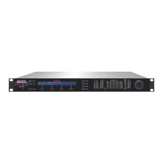
Page 60: 8600S Rear Panel
Procedures and instructions for connecting to a PC are subject to development and change. We advise you to download the latest version of this manual in pdf format from ftp.orban.com/8600S/Documentation. You can use Adobe’s .pdf reader application to open and read this file. If you do not have the .pdf reader, it is available for free download from www.adobe.com. -
Page 61: Input And Output Connections
OPTIMOD-FM DIGITAL INSTALLATION mono-right, mono-sum), selecting analog, digital or digital+J.17 input, overshoot compensation, SCA modulation compensation, and clock synchronization. (See Re- mote Control Interface Programming on page 2-45.) The 8600S remote control ac- cepts a DB-25 connector. The Ethernet Port accepts a 10Mb/second or 100Mb/second Ethernet connection terminated with an RJ45 connector. -
Page 62: Connectors
INSTALLATION ORBAN MODEL Connectors Input and output connectors are XLR-type connectors. In the XLR-type connectors, pin 1 is CHASSIS GROUND, while pin 2 and pin 3 are a balanced, floating pair. This wiring scheme is compatible with any studio-wiring standard: If pin 2 or 3 is considered LOW, the other pin is automatically HIGH. -
Page 63: Aes3 Digital Input And Output
OPTIMOD-FM DIGITAL INSTALLATION If an unbalanced output is required (to drive unbalanced inputs of other equip- ment), it should be taken between pin 2 and pin 3 of the XLR-type connector. Connect the L pin of the XLR-type connector (#3 or #2, depending on your organization’s standards) to circuit ground;... -
Page 64: Connecting A Ratings Encoder
INSTALLATION ORBAN MODEL The 8600S is a “multirate” system whose internal sample rate is 64 kHz and multi- ples thereof (up to 512 kHz). The outputs processed for analog FM are band-limited to 16.5 kHz, with a stopband that begins at 18 kHz. Therefore, the output can be passed through a 44.1 kHz (or higher) uncompressed link without adding significant... -
Page 65: Figure 2-3: Separation Vs. Load Capacitance
OPTIMOD-FM DIGITAL INSTALLATION given output to 75, place the link on pins 1 and 2 of its associated jumper. (See the schematic on page 6-38 and the parts locator diagram on page 6-34.) Each output can drive up to 75 in parallel with 0.047F before perform- ance deteriorates significantly (see Figure 2-3 on page 2-9). -
Page 66: Wordclock/10 Mhz Sync Reference
2-10 INSTALLATION ORBAN MODEL GROUND. always be set to Even when its composite limiter is being used heavily, the 8600S will al- ways protect the stereo pilot tone by at least 60 dB (250Hz from 19 kHz) and will protect the region from 55 kHz to 100 kHz by at least 75 dB (re 100% modulation). -
Page 67: Aes3Id Input
2-11 OPTIMOD-FM DIGITAL INSTALLATION To permit daisy-chaining sync signals, the input impedance is greater than 1 K. If the 5500 is the last device driven by the sync coaxial cable, you should terminate it by using a BNC Tee connector and a 75 BNC terminator. This will prevent perform- ance-degrading reflections in the cable. -
Page 68: Power Ground
[Skip this section if you are not using a studio level controller ahead of the 8600S. Continue with “Quick Setup” on page 2-15.] If you are using an Orban 6300 as a studio level controller, refer to its Operating Manual. If you are using Orban 8200ST external AGC... -
Page 69: Figure 2-4: 8200St Jumper Settings (*Factory Configuration)
2-13 OPTIMOD-FM DIGITAL INSTALLATION TOP OF MAIN BOARD Clipper Jumpers Output Pre-Emphasis Jumpers FLAT PRE-EMPHASIZED CLIPPER ON CLIPPER OFF LEFT RIGHT LEFT RIGHT OUTPUT OUTPUT OUTPUT OUTPUT Line-up Level Jumpers *PEAK LEFT RIGHT LEFT RIGHT OUTPUT OUTPUT OUTPUT OUTPUT Figure 2-4: 8200ST Jumper Settings (*Factory Configuration) - Page 70 2-14 INSTALLATION ORBAN MODEL 1. Configure the 8200ST’s internal jumpers. A) Remove all screws holding the 8200ST’s cover in place; then lift it off. Refer to Figure 2-4 on page 2-13. B) Place jumper JA in the C position. LIPPER C) If you have defeated the STL transmitter’s pre-emphasis, place jumpers JE and...
-
Page 71: Quick Setup
2-15 OPTIMOD-FM DIGITAL INSTALLATION GATE ....................12:00 RELEASE ....................12:00 VOICE ......................OFF AGC ......................ON COUPLE ....................ON C) Feed the 8200ST either with tone at your system reference level (0VU), or with typical program material at normal levels. D) Adjust the G control for the desired amount of gain reduction. - Page 72 2-16 INSTALLATION ORBAN MODEL If you leave Quick Setup before you complete all of the setup screens, re- invoking Quick Setup will return you to the screen you were on before you left Quick Setup. 3. Set the time. Note that if your 8600S can be connected to the Internet via its Ethernet jack, you can configure the 8600S’s internal clock to sync to an Internet...
- Page 73 If you are using an Orban 4000 Transmission Limiter, set field to (so that the AGC function in the 8600S continues to work). The Orban 4000 is a transmission system overload protection device; it is normally operated be- low threshold. It is not designed to perform an AGC or gain-riding function, and it cannot substitute for the AGC function in the 8600S.
- Page 74 2-18 INSTALLATION ORBAN MODEL C) Play program material from your studio, peaking at normal program levels (typically 0VU if your console uses VU meters). D) [Skip this step if you are not using the analog input.] Hold down the A...
- Page 75 2-19 OPTIMOD-FM DIGITAL INSTALLATION a) Press the Next button. b) Turn the knob to assign FM or FM+D as the source driving Digital ELAY Ouput #2. FM+D ELAY is used in HD Radio installations where the 8600S supplies the diversity delay. c) Press the Next button.
- Page 76 2-20 INSTALLATION ORBAN MODEL a) Press the Next button. b) [Skip this step if you will not be using Digital Output #1.] Turn the knob to set the Digital O to 32, 44.1, 48, 88.2, UTPUT AMPLE or 96 kHz.
- Page 77 2-21 OPTIMOD-FM DIGITAL INSTALLATION a) Press the Next button. b) [Skip this step if you are not using Digital Output #1.] Turn the knob to set the maximum desired output level in units of dB below full-scale (dBFS). The “true peak” limiter at the end of the 8600S’s HD processing chain is oversampled at 256 kHz and will prevent overshoots from exceeding 0.3 dB, even after sample rate conversion or D/A conversion.
- Page 78 2-22 INSTALLATION ORBAN MODEL following the instructions in step 1 on page 2-23. 13. Choose a processing preset. [If you are setting up the 8600S for use as a stand-alone stereo encoder, skip this step.] A) Turn the knob until your desired preset is visible in the lower line of the dis- play.
- Page 79 (e.g., “Z-100”). The name can be up to eight characters long. It is used to identify your 8600S to Orban’s PC Re- mote application, and appears on the Main Screen when the 8600S is being con- trolled by the PC Remote application.
- Page 80 2-24 INSTALLATION ORBAN MODEL 2. Set up modulation reduction to compensate for subcarriers, if needed. In the United States, F.C.C. Rules permit you to add 0.5% modulation for every 1% increase in subcarrier injection. For example, if your subcarrier injection to- tals 20%, you can set the total modulation to 110% (82.5 kHz deviation).
- Page 81 2-25 OPTIMOD-FM DIGITAL INSTALLATION 3. Program Silence Sense (optional) You can program the 8600S to switch automatically from its digital input to its analog inputs if the I is set to D and the signal at the digital in- NPUT OURCE IGITAL put falls silent.
-
Page 82: Analog And Digital I/O Setup
2-26 INSTALLATION ORBAN MODEL knob, the functions listed below will appear in the highlighted field. Input: Analog: Indicates that the 8600S is processing audio from its analog input. Input: Digital: Indicates that the 8600S is processing audio from its AES3 digital input. - Page 83 AGC to N . (It may be set to N already.) If you are using a external AGC like the Orban 6300, you should restore this setting to Y after the setup procedure is complete. 2. Adjust Input selector. A) Navigate to Setup > I/O C >...
- Page 84 (typically 0VU if your console uses VU meters). If you are using a studio level controller that performs an AGC function, such as an Orban 8200ST OPTIMOD-Studio, adjust it for normal opera- tion. c) Adjust the AI R (VU or PPM) control to make the 8600S’s AGC meter...
- Page 85 7. Defeat final clipper (optional). If you are using the 8600S to drive a network with protection audio processors (like Orban’s Optimod-FM 5500) at each transmitter, you may wish to defeat the 8600S’s final clipper to prevent double clipping, which will unnecessarily increase distortion on-air.
- Page 86 2-30 INSTALLATION ORBAN MODEL B) Set the FM P control to P or N OLARITY OSITIVE EGATIVE as appropriate for your transmitter. 9. Configure Composite Outputs A) Navigate to Setup > S > Next > P . Set the pre-emphasis...
- Page 87 2-31 OPTIMOD-FM DIGITAL INSTALLATION f) Set T to L+R. g) Verify that P is O ILOT h) Adjust the relevant output level control so that your peak modulation is 100%. i) When you have finished with the tone, set the M to O PERATE I) You can specify the amount by which the 8600S automatically reduces main...
- Page 88 2-32 INSTALLATION ORBAN MODEL C) You can use either program material or tone to set your output level (and thus, your on-air modulation). If you want to use tone, turn on the 100 Hz cal- ibration tone and set it to 91%.
- Page 89 2-33 OPTIMOD-FM DIGITAL INSTALLATION 11. Set digital output and configuration level. [Skip this step if you will not be using the digital outputs.] [See the notes in step 10 immediately above.] A) Navigate to Setup > I/O C > D ALIB ALIB B) Set the DO P...
- Page 90 2-34 INSTALLATION ORBAN MODEL [In] or [Out] When set to In, the 8600S adds “high-pass” dither before any truncation of the output word. The amount of dither automatically tracks the set- ting of the W control. This is first-order noise shaped dither...
- Page 91 2-35 OPTIMOD-FM DIGITAL INSTALLATION The Ratings Encoder Loop-through mode has a standard fallback strategy: To prevent an audio mute, your Optimod will automatically bypass the ste- reo encoder loop-though and will drive its stereo encoder from the output of its FM audio processing if there is no valid AES3 signal at your Optimod’s Sync Input.
- Page 92 2-36 INSTALLATION ORBAN MODEL country does not require this, leave the BS.1770 Safety Limiter off. It must be OFF if you are transmitting HD Radio. A) To use the BS.1770 Safety Limiter, assign the output source of one of the Digi- tal Outputs to HD.
- Page 93 2-37 OPTIMOD-FM DIGITAL INSTALLATION the result as a User Preset. We recommend allowing the BS.1770 Safety Lim- iter to produce no more than 3 dB of gain reduction. 13. Set up and activate the BS.1770 Safety Limiter in the analog radio proc- essing chain (optional) The adjustments in this step can only be done from PC Remote.
- Page 94 EBU Tech 3344 is correct in this initial release and we welcome any feedback. Please email Bob Orban at the address shown at http://www.orban.com/contact/ if you discover an error in our calibration.
-
Page 95: Automation Using The 8600S's Internal Clock
2-39 OPTIMOD-FM DIGITAL INSTALLATION 14. End Analog and Digital I/O setup. If you are using an external AGC and you temporarily set the E AGC to NO in step 1 on page 2-27, set the E AGC to Y 15. Select a processing preset. See step 13 on page 2-22. - Page 96 2-40 INSTALLATION ORBAN MODEL 2. Navigate to Setup > Next > Automation. If the A button reads D , hold it down and turn the knob to en- UTOMATION ISABLED able automation. This button allows you to easily enable or disable all automation events without having to edit individual automation events.
- Page 97 2-41 OPTIMOD-FM DIGITAL INSTALLATION mono-from right-channel (MONO-R) mode mono-from-sum-of-channels (MONO-SUM) bypass mode Independently activate and defeat the diversity delay applied to the ana- log, digital, and composite outputs. exit test (restores the operating preset that was on-air before a test mode was invoked) ...
-
Page 98: Security And Passcode Programming
2-42 INSTALLATION ORBAN MODEL Security and Passcode Programming [Skip this step if you do not plan to use PC Remote software or do not plan to lock out the front panel locally.] The 8600S has several levels of security to prevent unauthorized people from chang- ing its programming or operating state. -
Page 99: To Edit A Passcode
2-43 OPTIMOD-FM DIGITAL INSTALLATION Passcodes can be up to eight characters long but can only contain the characters “1,” “2,” “3,” and “4.” This limitation makes it easy to enter a passcode using the four available soft buttons. C) When you have finished entering your new passcode, write it down so you do not forget it. -
Page 100: To Program Local Lockout
2-44 INSTALLATION ORBAN MODEL B) Press the L soft button. To Program local lockout: A) Navigate to Setup > S ECURITY If the front panel is already password protected, you can only access this screen by entering a passcode with A privileges. -
Page 101: Remote Control Interface Programming
2-45 OPTIMOD-FM DIGITAL INSTALLATION A) Remove power from the 8600S. B) While pressing both the Escape and Setup buttons, restore power. The Restore Defaults screen appears. C) To gain access to the 8600S, press the E RASE ASSCODES soft button. D) Reprogram passcodes as necessary;... - Page 102 2-46 INSTALLATION ORBAN MODEL Exit Test: If a test mode (Tone or Bypass) is switched on the air, EXIT TEST reverts to the normal operating mode using the previous processing preset. Stereo: switches the 8600’s stereo encoder on using normal double side- band modulation of the stereo subchannel.
-
Page 103: Networking And Remote Control
2-47 OPTIMOD-FM DIGITAL INSTALLATION 3. End remote control interface programming. When you are finished programming the remote control interface, press the Es- cape button to return to higher menu levels. Networking and Remote Control [Skip this step if you do not wish to connect to your 8600S remotely, either for downloading software upgrades or for PC Remote Control.] The 8600S has a built-in Ethernet connector that can be used with 10 Mbps or 100 Mbps ports using the TCP/IP protocol. - Page 104 F) Press the S soft button to confirm your setting. 3. Modem setup: You will need two modems and two available phone lines, one of each for your PC and your 8600S. Orban Customer Service supports only the 3Com/U.S. Robot-...
-
Page 105: Connecting To The 8600'S Ethernet Port Or Serial Port Via A Terminal Program On A Pc
2-49 OPTIMOD-FM DIGITAL INSTALLATION ics® 56kbps fax modem EXT on the 8600S side of your connection, although oth- er 56kbps modems will often work OK. You can use either an internal or an external modem with your PC. A) Connect the telephone line from the wall phone jack to the wall connection icon on the back of the modem (modem in). -
Page 106: Direct Control Using Putty
2-50 INSTALLATION ORBAN MODEL This interface can be used to allow custom third-party applications (including auto- mation systems) to recall presets, view status and set the controls listed above. This connection uses the PPP protocol. To set a different port number: 1. -
Page 107: Automated Control Using Putty/Plink
2-51 OPTIMOD-FM DIGITAL INSTALLATION into the “Host Name (or IP address)” field. If you are connecting through the 8600’s Ethernet interface, type the 8600’s IP address into the “Host Name (or IP address)” field. The IP address for this connection is the same as the IP address set in step Setup >... -
Page 108: Automated Control Using Netcat
2-52 INSTALLATION ORBAN MODEL The file “8600_P1_Gregg.cmd” contains: plink -raw -P 23 123.45.67.89 < 8600_P1_Gregg.txt The file “8600_P1_Gregg.txt” contains: RP GREGG [PASSWORD] disconnect The file “8600_P2_GreggOpen.cmd” contains: plink -raw -P 23 123.45.67.89 < 8600_P2_GreggOpen.txt The file “8600_P2_GreggOpen.txt” contains RP GREGG OPEN [PASSWORD]... -
Page 109: Administrative Operations Available Via Serial Port / Ethernet
2-53 OPTIMOD-FM DIGITAL INSTALLATION Administrative Operations Available via Serial Port / Ethernet In the following tables of commands and responses: Text that the user enters appears in MONOSPACED BOLD. Responses that the 8600 transmits appear in monospaced normal. ... - Page 110 2-54 INSTALLATION ORBAN MODEL If a non-existent control value and/or an invalid passcode is entered, the 8600 will ignore the command. You can apply this command anytime after the 8600 boots up. The 30-minute timeout does not apply.
- Page 111 2-55 OPTIMOD-FM DIGITAL INSTALLATION For an explanation of why this can be useful, see step 8 on page 2-29). If a non-existent control value and/or an invalid passcode is entered, the 8600 will ignore the command. You can apply this command anytime after the 8600 boots up. The 30-minute timeout does not apply.
- Page 112 2-56 INSTALLATION ORBAN MODEL remote contact closure 6 [active][inactive] remote contact closure 7 [active][inactive] remote contact closure 8 [active][inactive] tally out 1 [active][inactive] tally out 2 [active][inactive] 7. To fetch information about the active processing preset: Command Response AP [PASSCODE]?...
-
Page 113: Synchronizing Optimod To A Network Time Server
2-57 OPTIMOD-FM DIGITAL INSTALLATION Synchronizing Optimod to a Network Time Server [Skip this section if you do not wish to automatically synchronize your Optimod’s in- ternal clock to a network timeserver, which may be part of your local network or lo- cated on the Internet.] 1. - Page 114 2-58 INSTALLATION ORBAN MODEL You can specify the timeserver either from your Optimod’s front panel or from its PC Remote software. From the front panel, you can only enter the time- server’s IP address (for example, 192.43.244.18). If you specify the timeserver from PC Remote, you can specify either its named address (for example, time.nist.gov) or its IP address.
- Page 115 2-59 OPTIMOD-FM DIGITAL INSTALLATION B) Set time zone to correspond to your local time zone. C) In Windows, navigate to the C > D > I ONTROL ANEL ATE AND NTERNET tab. D) If you are running Windows XP: a) Check “Automatically synchronize with an Internet time server” to set your Optimod’s S to “24.”...
-
Page 116: Installing 8600S Pc Remote Control Software
8600S’s serial port. (These services are also used to upgrade your 8600S’s firm- ware when updates are available from Orban.) The exact process will vary, depend- ing on how you wish to set up the communications. That is:... -
Page 117: Running The Orban Installer Program
You might have obtained the automatic installer application from some other source than Orban’s CD, like Orban’s ftp site or another computer on your net- work. If so, just run the application and follow the on-screen instructions. ... -
Page 118: Setting Up Ethernet, Lan, And Vpn Connections
8600S questions, please contact Orban Customer Service: phone: +1 856.719.9900 email: custserv@orban.com For details on your new 8600S software, from new features to operational sugges- tions, refer to our FTP site (ftp.orban.com/8600S). -
Page 119: Appendix: Setting Up Serial Communications
Windows Vista and 7, although we recommend us- ing Ethernet connections with Vista or 7. Note that the screen shots were prepared using Orban’s Optimod-FM 8300 but apply equally well to the 8600S. Preparing for Communication through Null Modem Cable 1. - Page 120 2-64 INSTALLATION ORBAN MODEL If you cannot access the Internet after making a Direct or Modem connection, you will have to reconfigure certain networking parameters in Windows. Please see You Cannot Access the Internet After Making a Direct or Modem Connection of the 8600S on page 5-9.
- Page 121 2-65 OPTIMOD-FM DIGITAL INSTALLATION i) In the drop-down box, select the serial port you will be using to make the connection. j) Click “Next.” k) Select either “For all users” or “Only for myself.” The correct setting depends on how your network and security are configured.
- Page 122 2-66 INSTALLATION ORBAN MODEL o) Click “Yes.” B) Edit your new Direct Connection properties: a) Click “Settings.” b) Click the “General” tab. c) Select the device you set up in step (i) on page 2-65. This will usually “Com- munications...
- Page 123 2-67 OPTIMOD-FM DIGITAL INSTALLATION e) Set “Maximum speed (bps)” “115200.” f) Check “Enable hardware flow con- trol.” g) Make sure that all other boxes are not checked. h) Click “OK.” i) Select the Networking tab. j) Make sure that “PPP: Windows 95/98/NT 4/2000, Internet”...
-
Page 124: Connecting Using Windows Xp Direct Serial Connection
2-68 INSTALLATION ORBAN MODEL 2. Launch an existing Windows 2000 Direct connection. Once you have set up a “connection” specifying Direct Connect in the 8600S PC Remote application (see To set up a new connection on page 3-89), choosing this connection from 8600S PC Remote automatically opens a Windows Direct Con- nection to your 8600S. - Page 125 2-69 OPTIMOD-FM DIGITAL INSTALLATION c) Give your 8600S a name (e.g., “KABC”) by entering this name in the “8600S Alias” field. d) If you wish to have 8600S PC Remote remember password this Optimod, enter the password in the “Password“ field. e) Select “Serial Connection.”...
- Page 126 2-70 INSTALLATION ORBAN MODEL k) Type in a name for your Connection such “Connection to 8600S.” l) Click “Finish.” n) Click “Yes.” B) Edit your Direct Connection properties: a) Click “Settings.”...
- Page 127 2-71 OPTIMOD-FM DIGITAL INSTALLATION b) Click the “General” tab. c) Select the device you set up in step (i) on page 2-69. This will usually be “Communications cable between two computers (COM1).” d) Click “Configure.” e) Set the “Maximum Speed (bps)” to 115200.
- Page 128 2-72 INSTALLATION ORBAN MODEL j) Select the Networking tab. k) Make sure that “PPP: Windows 95/98/NT 4/2000, Internet” appears in the “Type of dial-up server I am calling” field. l) Make sure that “Internet Protocol (TCP/IP) is checked. You may leave “File...
-
Page 129: Connecting Using Windows 7 Direct Serial Connection
2-73 OPTIMOD-FM DIGITAL INSTALLATION 3. To change the properties of an existing connection: Right-click the connection in the “connection List” window and choose “Proper- ties.” The “Connection properties” window opens (see page 2-64). Connecting Using Windows 7 Direct Serial Connection: You must install the Windows 7 direct serial connection as a modem device using the Modem setup procedures as shown in the steps below. - Page 130 2-74 INSTALLATION ORBAN MODEL B) In the Phone and Modem applet, click on the Mo- dems tab and click “Add.” You need ad- ministrator's rights to do this. If UAC comes up, provide the relevant creden- tials and pro- ceed.
- Page 131 2-75 OPTIMOD-FM DIGITAL INSTALLATION D) The Install New Modem window will appear. a) Select Communications cable between two computers. b) Proceed to next step by clicking on the NEXT button. E) Select the Serial com port to which the NULL cable is con- nected.
- Page 132 2-76 INSTALLATION ORBAN MODEL F) At the Modem installation is finished window, click FINISH to complete the in- stallation. G) Once you are back at the Phone and Modem win- dow, you will see your newly installed communi- cation cable attached to the serial com port that you specified earlier.
- Page 133 2-77 OPTIMOD-FM DIGITAL INSTALLATION A) Go to the Network and Sharing Center and click on Set up a new connection or network link. B) In the Choose a connection op- tion window, select Set up a di- al-up connection.
- Page 134 2-78 INSTALLATION ORBAN MODEL C) If you are asked Which mo- dem do you want to use?, se- lect Communications cable between com- puters/modem. This only query will open appear if you have configured more than modem device. D) When prompted to “Type...
- Page 135 2-79 OPTIMOD-FM DIGITAL INSTALLATION Windows will emit a message stating The connection is ready for use. How- ever, you must to configure some of the PPP settings before you can make a connection to your Optimod Although you did not specifically install any-...
- Page 136 2-80 INSTALLATION ORBAN MODEL B) In the Network adapter window, right-click the Direct Serial PPP icon and click on the properties. You need ad- ministrator rights to pro- ceed from here. If UAC comes up, pro- vide the rele- vant...
- Page 137 2-81 OPTIMOD-FM DIGITAL INSTALLATION c) If it is not correct, reset it to 115200 bps. d) Click OK to close the window. e) Click OK to dismiss the Properties window. f) Restart your computer. Restarting should ensure that the bps setting is saved. G) Select the Networking tab.
- Page 138 2-82 INSTALLATION ORBAN MODEL H) In the Advance TCP/IP Set- tings window, click on the Advance button. a) Unselect default gateway remote network. b) Click OK to close this window. This prevents Win- dows 7 from rout- ing all networking...
-
Page 139: Preparing For Communication Through Modems
You will need two modems and two available phone lines, one of each for your PC and your 8600S. Reminder: Orban supports only the 3Com / U.S. Robotics® 56kbps fax modem EXT on the 8600S side (although other 56kbps modems will often work OK). - Page 140 2-84 INSTALLATION ORBAN MODEL b) On your PC, click “Start / Settings / Control Panel / Phone and Modem Options.” c) Click the “Modems” tab. d) Verify that your modem appears in the list available under “The following Modems are installed.”...
- Page 141 2-85 OPTIMOD-FM DIGITAL INSTALLATION g) Select “Dial-up to private network.” h) Click “Next.” j) Enter the phone number of the modem connected to the 8600S that you are setting up. k) Click the “Next” button. l) Select either “For all users” or “Only for myself.”...
- Page 142 2-86 INSTALLATION ORBAN MODEL n) Click the “Next” but– ton. o) Type in a name for your Connection such “Connection 8600S – Modem.” p) Click the “Finish” but– ton. q) Click “Yes.” D) Edit your new Direct Connection properties: a) Click “Settings.”...
- Page 143 2-87 OPTIMOD-FM DIGITAL INSTALLATION b) Click the “General” tab. c) In the “Connect using” field, select the modem you will be using to make the connection on the PC side. d) Click “Configure.” e) Set “Maximum speed (bps)” “115200.” f) Check “Enable hard-ware flow...
- Page 144 2-88 INSTALLATION ORBAN MODEL k) Select the Networking tab. l) Make sure that “PPP: Windows 95 / 98 / NT 4 / 2000, Internet” appears in the “Type of dial-up server I am calling” field. m)Make sure that “Inter- net Protocol (TCP/IP) is checked.
-
Page 145: Connecting Using Windows Xp Modem Connection
2-89 OPTIMOD-FM DIGITAL INSTALLATION 3. To change the properties of an existing connection: Right-click the connection in the “connection List” window and choose “Proper- ties.” The “Connection properties” window opens (see page 2-84). Connecting using Windows XP Modem Connection 1. Add and configure modem for Windows XP: Skip this step if your modem is already configured and working. - Page 146 2-90 INSTALLATION ORBAN MODEL If you are using an external modem, connect the modem to a serial port on your PC and make sure the modem is connected to a working phone line. b) On your PC, click “Start / Settings / Control Panel / Phone and Modem Options.”...
- Page 147 2-91 OPTIMOD-FM DIGITAL INSTALLATION e) Click “Add.” The Windows New Connection Wizard starts up. f) Select “Serial Connection.” g) Click the “Add” button. h) Select “Dial-up to private network.” i) Click “Next.” k) Enter the phone number of the modem connected to the 8600S you are setting up.
- Page 148 2-92 INSTALLATION ORBAN MODEL p) Click “Yes.” D) Edit your new Direct Con- nection properties: a) Click “Settings.” b) Click the “General” tab. c) Select the modem you will be using to make the connection on the PC side. d) Click “Configure.”...
- Page 149 2-93 OPTIMOD-FM DIGITAL INSTALLATION e) Set “Maximum speed (bps)” “115200.” f) Check “Enable hardware flow control.” g) Check “Enable modem error control.” h) Check “Enable modem compression.” i) Make sure that no other box is checked. j) Click “OK.” k) Select the Networking tab. l) Make sure that “PPP: Windows 95 / 98 / NT4 / 2000, Internet”...
-
Page 150: Updating Your 8600S's Software
2-94 INSTALLATION ORBAN MODEL You can connect by selecting the desired con- nection from the drop-down list in the C ONNECT menu. You can also connect by double-clicking the connection in the “Connection List” window. If the connection is successful, a dialog bubble will appear on the bottom right hand corner of the screen verifying your connection. - Page 151 2-95 OPTIMOD-FM DIGITAL INSTALLATION 4. Update your 8600S. A) Attempt to initiate communication to your 8600S via your connection. See To initiate communication on page 3-90. 8600S PC Remote will automatically detect that the 8600S software ver- sion on your 8600S is not the same as the version of 8600S PC Remote. PC Remote will then offer to update your 8600S automatically.
-
Page 152: Snmp Support
Secondary Manger Port: (162) sets the address of a Secondary SNMP Port. SNMP Mib file The 8600.mib file is in the location where you installed your PC Remote application. The default 8600 install location is: Program Files\Orban\Optimod 8600 PC Remote Program Files(x86)\Orban\Optimod 8600 PC Remote SNMP Default Settings ... -
Page 153: Snmp Features
Secondary Manger (Alarm) Port: 162 SNMP Features Get/Query: Station Name System Diagnostics Orban (walks through all of the “get” commands and dis- plays their status.) Primary and Secondary Manager IP Primary and Secondary Manager Port ... - Page 154 2-98 INSTALLATION ORBAN MODEL SNMP Community String: The “SNMP Community string” is like a user id or password that allows access to a router's or other device's statistics. It is set at Optimod PC Remote to implement SNMP security. PRTG sends the community string along with all SNMP requests. If the community string is correct, the device responds with the requested information.
-
Page 155: Rds/Rbds Generator
2-99 OPTIMOD-FM DIGITAL INSTALLATION RDS/RBDS Generator Your Optimod includes a full-featured RDS/RBDS generator that supports dynamic PS. We presume that you are already familiar with the basics of RDS and you wish to implement RDS via your Optimod. See the References on page 2-109 for more about RBS and RBDS. -
Page 156: Table 2-1: System I/O Rds Controls And Defaults
2-100 INSTALLATION ORBAN MODEL Program Service (PS= / DPS=) Default: undefined Radio Text (RT= / TEXT=) Default: undefined Radio Text Speed (DRTS=) Default: Off Program Identification (PI=) Default: undefined Program Type (PTY=) Default: undefined Program Name (PTYN=) Default: undefined Music/Speech (MS=) -
Page 157: Using Processing Presets
2-101 OPTIMOD-FM DIGITAL INSTALLATION In the System I/O RDS tab, turn on the RDS generator by setting 57 kHz RDS con- trol to . You can also set up the Modulation level and all other RDS I/O controls in the System I/O RDS screens per the screenshot above. Table 2-1 shows a list of RDS controls available in System I/O. -
Page 158: Using The Terminal Server
2-102 INSTALLATION ORBAN MODEL Note that because of buffering to ensure reliable RDS encoding, there is a delay of about four seconds between when you change a control and when your Optimod puts it on-air. Using the Terminal Server The terminal server is another way to change RDS dynamically. Your Optimod will update the outgoing RDS to whatever RDS control value it receives via the terminal, overwriting the system and preset RDS values. - Page 159 2-103 OPTIMOD-FM DIGITAL INSTALLATION H) You may now type any of the terminal commands in the chart of RDS Termi- nal Commands below. If you have checked the Optimod’s T box, when you type a ERMINAL command, the Optimod will return a status line relevant to the command to the Telnet client, which will write it to the screen.
-
Page 160: Security
2-104 INSTALLATION ORBAN MODEL AF 23=0 AF 24=0 Security In the System I/O RDS control screen, you can set the RDS Terminal control security by specifying an RDS IP address from which to accept commands. Once set, this IP will be the only IP that can connect to the unit to update RDS. The 8600S will default to 0.0.0.0, which will allow any IP to connect to the RDS terminal control. - Page 161 2-105 OPTIMOD-FM DIGITAL INSTALLATION COMMAND PARAMETER INFORMATION EXAMPLE DRTS= RadioText Speed 0 = RadioText OFF DRTS=15 0,5,10,…45 (steps Refresh rate for RadioText mes- sage transmission (15 recommended for text mes- saging, higher values for RT+ ap- plications) Program 4-digit number PI=3D44...
- Page 162 2-106 INSTALLATION ORBAN MODEL COMMAND PARAMETER INFORMATION EXAMPLE TIME= Time Data Determines if time and date are TIME=0 (turn time transmitted in the RDS data transmission off)) stream; 0=No, 1=Yes. RDS= 57kHz RDS Sub- 0 = RDS subcarrier On RDS=1...
-
Page 163: Alternative Frequency Channel Numbers
2-107 OPTIMOD-FM DIGITAL INSTALLATION RESPONSES (none) Data that has been sent either has not reached the encoder (none) or the encoder has no response for that command. Table 2-2: Preset/Terminal RDS controls and defaults Alternative Frequency Channel Numbers CHAN CHAN CHAN CHAN 87.6... -
Page 164: Program Type (Pty)
2-108 INSTALLATION ORBAN MODEL CHAN CHAN CHAN CHAN 91.5 96.6 101.7 106.8 91.6 96.7 101.8 106.9 91.7 96.8 101.9 107.0 91.8 96.9 102.0 107.1 91.9 97.0 102.1 107.2 92.0 97.1 102.2 107.3 92.1 97.2 102.3 107.4 92.2 97.3 102.4 107.5 92.3... -
Page 165: Sca/Subcarrier Phase Relationship
2-109 OPTIMOD-FM DIGITAL INSTALLATION SCA/Subcarrier Phase Relationship During stereo broadcast, the SCA subcarrier must be locked either in-phase or in quadrature to the third harmonic of the 19 kHz pilot tone. The tolerance of the phase angle is ±10° measured at the modulation input to the FM transmitter. With no modulation other than the pilot tone, an oscilloscope trigged from the 19kHz pilot tone should display the following: Figure 2-5: Pilot/SCA Phasing Scope Trace... -
Page 167: Section 3 Operation
OPTIMOD-FM DIGITAL OPERATION Section 3 Operation 8600S Front Panel Screen Display labels the four soft buttons and provides control-setting infor- mation. Screen Contrast button adjusts the optimum viewing angle of the screen dis- play. Four Soft buttons provide access to all 8600S functions and controls. The func- tions of the soft buttons change with each screen, according to the labels at the bottom of each screen. - Page 168 OPERATION ORBAN MODEL 8600S Input meters show the peak input level applied to the 8600S’s analog or digital inputs with reference to 0 = digital full-scale. If the input meter’s red segment lights up, you are overdriving the 8600S’s analog to digital converter, which is a very common cause of audible distortion.
- Page 169 OPTIMOD-FM DIGITAL OPERATION Gate LED indicates gate activity, lighting when the input audio falls below the threshold set by the multiband gate threshold control (with the Full Modify screen’s 2B G control). When this happens, the multiband compressor’s recov- ery time slows drastically to prevent noise rush-up during low-level passages.
-
Page 170: Introduction To Processing
OPERATION ORBAN MODEL 8600S Introduction to Processing Some Audio Processing Concepts Reducing the peak-to-average ratio of the audio increases loudness. If peaks are re- duced, the average level can be increased within the permitted modulation limits. The effectiveness with which this can be accomplished without introducing objec- tionable side effects (such as pumping or intermodulation distortion) is the single best measure of audio processing effectiveness. -
Page 171: Distortion In Processing
In FM processing, there is a direct trade-off between loudness, brightness, and dis- tortion. You can improve one only at the expense of one or both of the others. Thanks to Orban’s psychoacoustically optimized designs, this is less true of Orban processors than of others. -
Page 172: Fundamental Requirements: High-Quality Source Material And Accurate Monitoring
CDs that this energy cannot possibly survive the FM pre-emphasis / de- emphasis process. Although the 8600S loses less high frequency energy than any previous Orban processor (due to improvements in high frequency limiting and clip- ping technology), it is nevertheless no match for CDs that are mastered so bright... -
Page 173: About The 8600S's Signal Processing Features
OPTIMOD-FM DIGITAL OPERATION that they will curl the vinyl off car dashboards. We hope that the record industry will come to its senses when it hears the consequences of these practices on the air. If the waveforms on a given CD are noticeably clipped, it may be possible to improve the sound by using de-clipping software , which attempts to reconstruct the clipped- off sections of the waveform by extrapolating the clipped-off part of the waveform... - Page 174 Stereo Enhancement: The 8600S provides two different stereo enhancement algo- rithms. The first is based on Orban’s patented analog 222 Stereo Enhancer, which in- creases the energy in the stereo difference signal (L–R) whenever a transient is de- tected in the stereo sum signal (L+R).
- Page 175 622B), using a sophisticated, proprietary optimization program. The curves are matched to better than 0.15 dB. This means that their sound is very close to the sound of an Orban analog parametric. They also use very high quality filter algo- rithms to ensure low noise and distortion.
- Page 176 See To Override the Speech/Music Detector on page 3-70. DSP-derived Stereo Encoder: The 8600S’s stereo encoder is derived from algo- rithms first developed for the high-performance Orban 8218 stand-alone encoder. The 8600S’s stereo encoder operates at 512 kHz-sample rate to ease the perform- ance requirements of the D/A converter’s reconstruction filter, making it possible to...
- Page 177 3-11 OPTIMOD-FM DIGITAL OPERATION The 8600S has two independent composite outputs, whose levels are both software- settable. For convenience, two SCA inputs sum into the 8600S’s analog composite output amplifier. The second SCA input can be configured to provide a 19 kHz- reference output for subcarrier generators that need it.
- Page 178 IMIT RIVE control as usual Composite Limiter/Clipper: Orban has traditionally opposed composite clipping because of its tendency to interfere with the stereo pilot tone and with subcarriers, and because it causes inharmonic aliasing distortion, particularly between the stereo main and subchannels. Protecting the pilot tone and subcarrier regions is particu- larly difficult with a conventional composite clipper because appropriate filters will not only add overshoot but also compromise stereo separation—filtering causes the...
-
Page 179: Itu-R 412 Compliance For Analog Fm Broadcasts
3-13 OPTIMOD-FM DIGITAL OPERATION harmonics as if they were L–R information and the decoded harmonics appear at new frequencies not harmonically related to the original frequency that generated them. While the processing never clips the pilot tone, the extra spectrum generated by the processing can fall into the 19 kHz region, compromising the ability of receivers to recover the pilot tone cleanly. -
Page 180: Digital Radio Processing
3-14 OPERATION ORBAN MODEL 8600S with look-ahead limiting. Sophisticated multiband high frequency limiting and dis- tortion-cancelled clipping complete the chain. We believe that this is the ideal processing for classical music because it does not dy- namically re-equalize high frequencies; the subtle HF limiter only acts to reduce high frequency energy when it would otherwise cause overload because of the FM pre- emphasis curve. -
Page 181: Bs.1770 Compliance For Digital Radio
3-15 OPTIMOD-FM DIGITAL OPERATION With the FMHD C set to I , there are several ap- ONTROL OUPLING NDEPENDENT proaches to minimizing brightness and conditioning the signal to work well at low bitrates. Use little or no high frequency boost in the HD equalization and band mix sec- tions. -
Page 182: Customizing The 8600S's Sound
8600S users will never need to go beyond the Basic level of control. The combinations of subjective setup control settings produced by this control have been optimized by Orban’s audio processing experts on the basis of years of experience designing audio processing, and upon hundred of hours of listening tests. -
Page 183: Advanced Modify
In the 8600S, L affects only the dynamics processing (compression, limiting, and clipping). Unlike Orban’s OPTIMOD-FM 8200, the 8600S has equalization and stereo enhancement that are decoupled from L . You can therefore change EQ or stereo enhancement and not lose the ability to use L . -
Page 184: To Create Or Save A User Preset
3-18 OPERATION ORBAN MODEL 8600S To accommodate the FM pre-emphasis curve, Band 5 of the Five-Band Structure is capable of 30 dB of gain reduction. Further, be aware of the different peak factors on voice and music — if voice and... -
Page 185: About The Processing Structures
3-19 OPTIMOD-FM DIGITAL OPERATION ory (as if you had saved them from the 8600S’s front panel). The PC Remote ap- plication also allows you to archive presets to your computer’s hard drive (or other storage device) and to restore them. However, archiving a preset is not the same as saving it. -
Page 186: Factory Programming Presets
Unused structures operate constantly in the background, so switching between structures occurs with a seamless cross-fade. Unlike older Orban processors like the 8200, no DSP code is reloaded and no audio mute is necessary. - Page 187 3-21 OPTIMOD-FM DIGITAL OPERATION FACTORY PROGRAMMING PRESETS GOLD GOLD GOLD HEAVY MX GOLD HEAVY MX GOLD HEAVY BASS MX GOLD HEAVY BASS MX GOLD OPEN MX GOLD OPEN MX GREGG GREGG GREGG MX GREGG MX GREGG OPEN GREGG OPEN GREGG OPEN MX GREGG OPEN MX GREGG LL GREGG LL...
-
Page 188: Table 3-1: Factory Programming Presets
Bass, Mid EQ, and HF EQ controls. Un- ASIC ODIFY like Orban’s 8200, you can make changes in EQ (and stereo enhancement) without losing the ability to use L settings. Of course, L is still available for the unedited preset if you want to go back to it. - Page 189 3-23 OPTIMOD-FM DIGITAL OPERATION iter to achieve the highest performance available in the 8600S. MX presets offer greater transient impact, less preemphasis-induced high frequency loss, and low- er perceived distortion than their 8500-technology counterparts. Achieving this level of performance requires the MX presets to have much longer delays (typi- cally 265 milliseconds) than the 8500-style presets.
- Page 190 3-24 OPERATION ORBAN MODEL 8600S more automatic re-equalization than the CLASSICAL 2-BAND preset provides, use the CLASSICAL 5-BAND preset. CLASSICAL-5B+AGC uses the AGC set for 2:1 compression ratio. Because of the AGC, it affects more of the total dynamic range of the recording than does the CLASSICAL-5 BAND preset.
- Page 191 3-25 OPTIMOD-FM DIGITAL OPERATION distortion. Because of its lower distortion, EDGE MX is appropriate for both 75 µs and 50 µs pre-emphasis. EDGE, EDGE MX: This preset is designed for hit music, urban, and dance-oriented stations that prefer extremely punchy bass to fastidious distortion control. The 8500- style version uses H bass clipping, is loud, and has a bright high frequency tex- ture.
- Page 192 GREGG, GREGG MX: GREGG, GREGG MX, GREGG OPEN, GREGG OPEN MX, and GREGG LL all use a 200 Hz band1/band2 crossover frequency to achieve a bass sound similar to the classic five-band Gregg Labs FM processors designed by Orban’s Vice President of New Product Development, Greg Ogonowski. Dynamically, these presets produce a slight increase in bass energy below 100 Hz and a decrease of bass energy centered at 160 Hz.
- Page 193 3-27 OPTIMOD-FM DIGITAL OPERATION Stations programming “smooth jazz” should investigate the SMOOTH JAZZ MX pre- set, which is louder and more “commercial”-sounding. There is also an 8500-style SMOOTH JAZZ preset available. LOUD: There are several LOUD presets, all of which use “8500-style” technology and typically have 18 ms of latency.
- Page 194 3-28 OPERATION ORBAN MODEL 8600S LOUD-PUNCHY is the quietest of the “loud” preset family. It is designed for a bright, sizzling top end and very punchy lows. It is a good choice for stations that feel that the LOUD-HOT presets are too aggressive, but that think that the ROCK presets are insufficiently loud for their market position.
-
Page 195: Equalizer Controls
3-29 OPTIMOD-FM DIGITAL OPERATION ROCK-SOFT has a mellow, easy-to-listen-to high frequency quality that is designed for female-skewing formats. It is also a candidate for “Quiet Storm” and “Love Songs” light rock or light urban formats. ROCK-SMOOTH has the same mellow, easy-to-listen-to high frequency quality as ROCK-SOFT, but with more density. - Page 196 3-30 OPERATION ORBAN MODEL 8600S Most equalization controls are common to both the Two-Band and Five-Band struc- tures. The equalizer is located between the AGC and multiband compressor sections of both structures. Any equalization that you set will be automatically stored in any User Preset that you create and save.
-
Page 197: Table 3-2: Five-Band Equalization Controls
Low Frequency Parametric Equalizer is a specially designed parametric equalizer whose boost and cut curves closely emulate those of a classic Orban analog para- metric equalizer with conventional bell-shaped curves (within 0.15 dB worst-case). - Page 198 100Hz in combination with a Bass Shelf boost at 6 dB/octave. The equalizer, like the classic Orban analog parametrics such as the 622B, has con- stant “Q” curves. This means that the cut curves are narrower than the boost curves.
- Page 199 3-33 OPTIMOD-FM DIGITAL OPERATION increasing the gain reduction in both the 3.7 kHz and 6.2 kHz bands. You may wish to compensate for this effect by turning up the control. RILLIANCE Use the mid frequency equalizer with caution. Excessive presence boost tends to be audibly strident and fatiguing.
-
Page 200: Stereo Enhancer Controls
The stereo enhancer is common to the FM and HD processing chains. You can oper- ate it in one of two modes or “styles.” The first emulates the Orban 222 analog ste- reo enhancer, while the second mode, called Delay, emulates a popular enhancer... -
Page 201: Table 3-3: Stereo Enhancer Controls
3-35 OPTIMOD-FM DIGITAL OPERATION Stereo Enhancer Controls PC Remote Name Range Amount 0.0 ... 10.0 In / Out Out / In Ratio Lim 70 … 100% Diffusion Off, 0.3 ... 10.0 Style 222 / Delay Depth 0 … 10 Table 3-3: Stereo Enhancer Controls original L–R to create stereo enhancement. -
Page 202: Agc Controls
This control is usually used to defeat the AGC when you want to create a preset with minimal processing (such as a CLASSICAL preset). The AGC is also ordinarily de- feated if you are using an external AGC (like Orban’s 6300). However, in this case it is AGC Controls... - Page 203 3-37 OPTIMOD-FM DIGITAL OPERATION better to defeat the AGC globally in the System Setup screen. AGC Drive control adjusts signal level going into the slow dual-band AGC and therefore determines the amount of gain reduction in the AGC. This also adjusts the “idle gain”—the amount of gain reduction in the AGC section when the structure is gated.
- Page 204 3-38 OPERATION ORBAN MODEL 8600S There are two independent gating circuits in the 8600S. The first affects the AGC and the second affects the multiband compressor. Each has its own threshold con- trol. The multiband compressor gate causes the gain reduction in bands 2 and 3 of the multiband compressor to move quickly to the average gain reduction occurring in those bands when the gate first turns on.
- Page 205 Previous Orban AGCs had compression ratios very close to :1, which produces the most consistent and uniform sound. However, the 8600S compressor can reduce this ratio to as low as 2:1.
- Page 206 3-40 OPERATION ORBAN MODEL 8600S As the AGC B control is moved towards 0 dB, the AGC B OUPLING HRESH control affects the sound less and less. The interaction between the AGC B control and the AGC B HRESH OUPLING...
-
Page 207: Peak Limiter Controls
Modify, all of the peak limiter controls common to 8500-style and MX Presets appear in both the Intermediate Modify and Advanced Modify screens. Composite Limit Mode determines if the composite limiter will operate as a hard clipper or as Orban’s patented “Half-Cosine Interpolation” composite limiter (which is not a clipper). -
Page 208: Table 3-5: Peak Limiter Controls Common To 8500-Style And Mx Presets
3-42 OPERATION ORBAN MODEL 8600S When operating as a hard clipper, the composite limiter will produce maximum brightness in the frequency range from 5 to 15 kHz because, unlike the 8600S’s left/right audio-domain peak limiters, it can produce square waves in this frequency range. The downside compared to Half- Cosine mode is that it can noticeably compromise stereo imaging. -
Page 209: Figure 3-1: 0-100 Khz Baseband Spectrum (Loud-Hot Preset)
3-43 OPTIMOD-FM DIGITAL OPERATION The 8600S’s composite limiter always protects frequencies above 53 kHz. However, the 19 kHz notch filter can introduce substantial overshoot with certain program material when the composite limiter is driven hard. For example, if the composite limiter limits energy at 6.33 kHz, the 19 kHz notch filter will remove the third harmonic produced by the limiting. - Page 210 3-44 OPERATION ORBAN MODEL 8600S This is because the Belar demodulates a bandwidth wider than 250 Hz around the pilot. A spectrum analyzer will reveal that, in fact, the pilot is protected by at least 60 dB in this 500 Hz wide area of the spectrum.
- Page 211 3-45 OPTIMOD-FM DIGITAL OPERATION operates the clipper like the clipper in the 8200. It produces the most har- monic distortion. This can be useful if you want maximum bass punch, because this setting allows bass transients (like kick drums) to make square waves. The peak level of the fundamental component of a square wave is 2.1 dB higher than the peak level of the flat top in the square wave.
-
Page 212: 8500-Style Peak Limiter Controls
HAPE are only available in the Advanced Modify screen. Bass Clip Thresh sets the clipping threshold of Orban’s patented embedded bass clipper, which is used only in the FM processing chain and not in the HD chain. The clipper is embedded in the multiband crossover so that any distortion created by clipping is rolled off by part of the crossover filters. -
Page 213: Advanced 8500-Style Peak Limiter Controls
3-47 OPTIMOD-FM DIGITAL OPERATION HF Clipping determines the amount of protection provided by the 8600S’s high frequency multiband clipper. This control was first introduced in the 8200 and al- lowed users to trade off distortion against brightness. Because of subsequent im- provements in the clipping system, this control is much less useful than it was in the 8200 and we recommend always setting it to “0.”... -
Page 214: 8600S Mx Technology Peak Limiter Controls
3-48 OPERATION ORBAN MODEL 8600S ware. Overshoot Drive (Overshoot Compensation Drive) sets the drive into the overshoot compensator with reference to the final clip threshold, in units of dB. The normal setting is “0 dB.” The overshoot compensator can produce audible distortion on material with strong high frequency content (like bell trees) and this control lets you trade off this distortion against loudness. -
Page 215: Table 3-7: Mx Technology Peak Limiter Controls
3-49 OPTIMOD-FM DIGITAL OPERATION The MX technology peak limiter consists of two main stages—first, a pre-limiter stage to control low frequency and high frequency peaks ahead of the main peak limiter and then the main peak limiter, which uses various proprietary techniques to control distortion, minimize transient loss, and minimize high frequency loss. - Page 216 Because the MX peak limiter uses newly developed algorithms that differ from those used by past Orban proces- sors, the loudness/distortion/brightness/punch tradeoffs are also different and it is worthwhile to take the time to get a feel for the MX limiter’s capabilities.
-
Page 217: The Two-Band Structure
Five-Band structure. Like the “Two-Band Purist” structure in Orban’s OPTIMOD-FM 8200, the 8600S’s Two-Band Structure is phase-linear throughout to maximize sonic transparency. The Two-Band structure has an open, easy-to-listen-to sound that is similar to the source material if the source material is of good quality. -
Page 218: Setting Up The Two-Band Structure For Classical Music
3-52 OPERATION ORBAN MODEL 8600S PROTECTION 5DB if you want about 5 dB of limiting to occur at the maximum normal input level. The L control affects only the input drive, and you can use it to set a nomi- nal limiting level different from 0 dB or 5 dB. -
Page 219: Customizing The Settings
3-53 OPTIMOD-FM DIGITAL OPERATION CLASSICAL-5 BAND There are also two five-band classical presets. The preset uses the five-band structure with AGC defeated. It uses substantial interband coupling to re- tain much of the frequency balance of the original source, but is capable of some- CLASSICAL-2 BAND what more “automatic equalization”... -
Page 220: Table 3-8: Two-Band Controls
3-54 OPERATION ORBAN MODEL 8600S 2B Release control determines how fast the two-band compressor releases (and therefore how quickly loudness increases) when the level of the program material decreases. This release time only applies when the Two-Band Compressor is not gat- ed by the silence gate. - Page 221 3-55 OPTIMOD-FM DIGITAL OPERATION With faster 2B R ELEASE control settings (above 8 dB / second), the sound will change substantially with the amount of gain reduction in the two-band compressor. This means that you should activate the gain-riding AGC to ensure that the two-band compressor is always being driven at the level that produces the desired amount of gain reduction.
- Page 222 3-56 OPERATION ORBAN MODEL 8600S Settings toward 100% (wideband) make the output sound most like the input. Be- cause setting the 2B B OUPLING control at 100% will sometimes cause bass loss, the most accurate frequency balance will often be obtained with this control set be- tween 70% and 90%.
-
Page 223: The Five-Band Structure
3-57 OPTIMOD-FM DIGITAL OPERATION The relationship and interaction of the next four controls is complicated and is best appreciated by listening and experimenting: 2B Clipping is a compression threshold control that affects the bass and master bands equally. It sets the drive level to the high frequency limiting and multiband distortion-controlling processing that precedes the final clipping section. -
Page 224: Putting The Five-Band Structure On The Air
3-58 OPERATION ORBAN MODEL 8600S Unlike the Two-Band structure, whose two-band compressor has a continuously var- iable release time, the release time of the Five-Band compressor is switchable to sev- en increments between slow and fast. Each setting makes a significant difference in the overall flavor and quality of the sound. -
Page 225: The Five-Band Structure's Full And Advanced Setup Controls
3-59 OPTIMOD-FM DIGITAL OPERATION tion sound. Nevertheless, as with any audio processing system, proper adjustment of these controls requires proper balancing of the trade-offs between loudness, den- sity, and audible distortion. The following provides the information you need to ad- just the Five-Band structure controls to suit your format, taste, and competitive situ- ation. -
Page 226: Table 3-10: Multiband Controls
3-60 OPERATION ORBAN MODEL 8600S To avoid excessive density with the F multiband release time, we rec- ommend using no more than 5 dB gain reduction in band 3 and compen- sating for any lost loudness by speeding up the MB R instead. - Page 227 3-61 OPTIMOD-FM DIGITAL OPERATION structure provides gentle automatic equalization to keep the frequency balance consistent from record to record (especially those recorded in different eras). For background music formats, these settings ensure that your sound doesn’t lose its highs and lows. Because it creates a more consistent frequency balance between different pieces of source material than does the Two-Band structure, S almost always preferable to the Two-Band structure for any popular music for- mat.
-
Page 228: Table 3-11: Mb Attack / Release Controls
3-62 OPERATION ORBAN MODEL 8600S the AGC is operated slowly for gentle gain riding only. These slower sounds are less consistent than those produced by the F setting. Using S preserves more of the source’s frequency balance, making the sound less dense and fatigu- ing when the radio is played loudly. - Page 229 3-63 OPTIMOD-FM DIGITAL OPERATION V1.x software. Driving the MB gate detector after the AGC allows the AGC to do its work of slowly correcting the drive level to later processing, including the multiband gate. When the AGC produces 10 dB of gain reduction, the calibration of the MB GATE control in V2.x software is the same as it was in V1.x software.
- Page 230 3-64 OPERATION ORBAN MODEL 8600S causing extra gain reduction in the multiband compressor. You can see the effect of this extra gain reduction on the gain reduction meters. Ordinarily, the gating on the AGC and multiband limiter will prevent objectionable build-up of noise and you will want to use the single-ended noise reduction only on unusually noisy program material.
- Page 231 3-65 OPTIMOD-FM DIGITAL OPERATION Band 4 > 5 Coupling control extent to which the gain of band 5 (6.2 kHz and above) is determined by and follows the gain of band 4. The sum of the high frequency limiter control signal and the output of the B 4 >...
-
Page 232: Table 3-12: Mb Band Mix Controls
3-66 OPERATION ORBAN MODEL 8600S On/Mute switches allow you to listen to any band (or any combination of bands) in- dependently. This is a feature designed for intermediate or advanced users and de- velopers when they are creating new 8600S presets. The mute control for a given band affects both the FM and HD processing because it mutes the input of compres- sor in that band. - Page 233 3-67 OPTIMOD-FM DIGITAL OPERATION You can use these controls to set independent frequency balances for music and speech (page 3-69). B1-B5 Attack (Time); Speech B1-B5 Attack controls set the speed with which the gain reduction in each band responds to level changes at the input to a given band’s compressor for music and speech respectively, following the 8600S’s automatic speech/music detector.
- Page 234 3-68 OPERATION ORBAN MODEL 8600S Max Dist Ctrl; Speech Max Dist Ctrl (available in 8500-style presets only) limit the maximum amount of final clipper drive reduction (in dB) that the 8600S’s clipping distortion controller can apply in Music and Speech modes respectively, preventing over-control of transient material by the distortion controller.
- Page 235 3-69 OPTIMOD-FM DIGITAL OPERATION Limiter Attack controls allow you to set the limiter attack anywhere from 0 to 100% of normal in the Five-Band compressor / limiters. Because the limiter and com- pressor characteristics interact, you will usually get best audible results when you set these controls in the range of 70% to 100%.
-
Page 236: To Override The Speech/Music Detector
Model 8600SFM can be upgraded to an 8600SHD in the field via the 8600SUPG/HD upgrade kit, which can be purchased from your Orban dealer. Units are upgraded from a PC; it is unnecessary to remove the 8600S from the rack. - Page 237 3-71 OPTIMOD-FM DIGITAL OPERATION The equalizer and five-band compressor/limiter in the HD processing chain have their own sets of user-adjustable audio controls that are independent of the controls in the FM analog transmission chain’s equalizer and five-band compressor/limiter. This allows you to optimize the HD processing for the higher fidelity sound provided by the digital channel while giving you the flexibility to process the analog channel as you wish.
-
Page 238: Delay Difference Between Hd And Fm Outputs
3-72 OPERATION ORBAN MODEL 8600S instead allowing the codec to use its entire bit budget to encode the desired pro- gram material. The 8600SHD’s look-ahead limiter implements “true peak” control by oversampling the HD peak limiter’s sidechain at 256 kHz. This allows the 8600S to prevent clipping in a playback device’s analog signal path by predicting and controlling the analog... -
Page 239: Hd I/O Setup Controls
3-73 OPTIMOD-FM DIGITAL OPERATION between presets of different types (like an 8500-style news preset and a music- oriented MX preset), the following must be true: The delay from the 8600S’s input to its FM analog processed output must not change when a preset is recalled (to prevent a audio segment from being re- peated or dropped due to different time delays between presets). -
Page 240: Table 3-13: Hd I/O Setup Controls
3-74 OPERATION ORBAN MODEL 8600S The HD look-ahead limiter is not stereo-coupled. This prevents limiting on one channel from causing audible modulation effects on the other channel. HD HF Shelf EQ (Pre/Post) determines whether the HD HF shelving equalizer will be placed before or after the look-ahead limiter that feeds the HD output. - Page 241 3-75 OPTIMOD-FM DIGITAL OPERATION mouse wheel to fine-tune the delay in one-sample adjustment increments. Maximum available delay is approximately 16 seconds. See the documentation provided with your HD Radio exciter for more in- formation on setting the delay correctly. You can adjust the diversity delay time via the 8600S’s API. See page 2-54. St.
-
Page 242: Digital Output
3-76 OPERATION ORBAN MODEL 8600S Digital Output The AES1 digital output is normally used to drive the digital transmitter. However, L/R, AES1, and AES2). The digital outputs have the you can use any output (A NALOG following controls, located in the I... -
Page 243: Unique Hd Audio Controls
3-77 OPTIMOD-FM DIGITAL OPERATION tal input, or to an AES11 signal appearing at the 8600S’s sync input. S can be set separately for Digital Output 1 and Digital Output 2, allowing them to have differ- ent sample rates. The selections for each of the two AES outputs are I , and NTERNAL sets a given AES3 output sample rate and synchronization to... -
Page 244: Table 3-14: Unique Hd Audio Controls (In Hd Distortion Page In Pc Remote)
3-78 OPERATION ORBAN MODEL 8600S dependent. The FMHD mode causes almost all HD controls to track the settings of their FM counterparts. Only the controls in the HD L IMITING page are adjustable sepa- rately. The I mode allows you to set the HD equalizer and HD multiband NDEPENDENT compressor/limiter audio controls independently of their FM counterparts. - Page 245 3-79 OPTIMOD-FM DIGITAL OPERATION HD EQ Freq sets the corner frequency of the parametric HF shelving equalizer. HD Limiter Dr sets the drive level to the digital-channel look-ahead limiter. When the digital radio BS.1770 Safety Limiter is active, you must use the HD control to set the amount of gain reduction that the BS.1770 Safety IMITER Limiter produces.
-
Page 246: Itu-R Multiplex Power Controller
3-80 OPERATION ORBAN MODEL 8600S chain. Therefore, you can activate the HD Band 5 compressor to either complement or replace the control that the HD DE-ESS control provides. ITU-R Multiplex Power Controller The ITU-R recommends that the power in the composite baseband signal (including the pilot tone), integrated over any 60-second interval, not exceed the power in a sinewave that modulates the FM carrier to 19 kHz (25.3% modulation re ±75 kHz... -
Page 247: Multiplex Power Threshold
3-81 OPTIMOD-FM DIGITAL OPERATION Assuming that the subcarrier and composite signal are uncorrelated and that the composite signal is limited so that its power is equivalent to a sinewave at 25.3% modulation, we calculate their R.M.S. sum as follows: ... -
Page 248: Figure 3-3: Multiplex Power Over 15 Minute Observation Interval With Multiplex Power Controller Active, Measured At The Optimod's Composite Output
3-82 OPERATION ORBAN MODEL 8600S much as 12 dB depending on the dynamics and spectral content of the input pro- gram material. To prevent unnatural loudness variations, your Optimod applies a static loss (preset-dependent and set by the M control) before... -
Page 249: About The Multiplex Power Controller's Time Constants
3-83 OPTIMOD-FM DIGITAL OPERATION applied to the stereo encoder. The multiplex power controller is operational with all of the Two-Band and Five- Band processing structures. It is not active in Test mode and will not prevent the 8600S’s test oscillator from producing illegal modulation. It is the responsibility of the operator to make sure that the test oscillator does not violate the ITU require- ments. -
Page 250: Test Modes
3-84 OPERATION ORBAN MODEL 8600S Test Modes Setup: Test Parameter Units Default Range (CCW to CW) Step Labels MODE Operate Operate, Bypass, Tone 18 … +25 BYPASS GAIN TONE FREQ 16, 20, 25, 31.5, 40, 50, 100, 125, 160, 200, 250, 315, 400, 500,... -
Page 251: Getting The Bass Sound You Want
OPERATION While this calibration may seem unintuitive, experience has shown that it greatly reduces calls to Orban customer service complaining that the frequency response of the transmission path is not flat when in fact the measurement in question was causing undetected clipping at high frequencies due to preemphasis. - Page 252 3-86 OPERATION ORBAN MODEL 8600S TTACK settings in the factory presets have been adjusted with this tradeoff in mind, but you might prefer to make a different one. The threshold of the band 1 compressor will also affect bass punch. We recommend...
-
Page 253: Bass Punch In The Mx Presets
3-87 OPTIMOD-FM DIGITAL OPERATION two GREGG presets.) The rest of the presets use the 100 Hz crossover and have more mid-bass. Bass Punch in the MX Presets The MX presets have two controls that allow you to trade off IM distortion against bass punch: B and B . - Page 254 3-88 OPERATION ORBAN MODEL 8600S...
-
Page 255: Using The 8600S Pc Remote Control Software
Before running 8600S PC Remote, you must have installed the appropriate Windows communications services on your computer. By default, the installer installs a short- cut to 8600SPC.exe on your desktop and in your Start Menu under Orban\Optimod 8600S. 8600S PC Remote can control only one 8600S at a time, but it can readily switch be- tween several 8600S. -
Page 256: To Initiate Communication
“Loading system files, please wait.” When run, the Orban PC Remote software installer makes copies of all 8600S fac- tory preset files on your local hard drive. The PC Remote software reads these files to speed up its initialization. -
Page 257: To Modify A Control Setting
3-91 OPTIMOD-FM DIGITAL OPERATION sage for the function you have selected. To modify a control setting: A) Choose P from the E ROCESSING ARAMETERS menu. B) Select menu tabs for Less-More, Stereo Enhancer, and EQ to access Basic Mod- ify controls. All other menu tabs contain Full or Advanced Modify controls. You can reset any Basic Modify Control without losing L func- tionality;... -
Page 258: To Back Up User Presets, System Files, And Automation Files Onto Your Computer's Hard Drive
The encryption options prevent archived presets, system files, and auto- mation files from being restored if the user does not have the password used for the encryption. There is no “back door”— Orban cannot help you to decrypt a preset whose password is unknown. - Page 259 All User Presets are compatible with all 8600S software versions and are compatible with both 8600SHD and 8600SFM. If Orban adds new controls to a software version, the new software will assign a reasonable default value to any control missing in an old User Preset.
-
Page 260: To Modify I /O And S
3-94 OPERATION ORBAN MODEL 8600S b) Highlight all the user presets in the dialog window c) Click the R ESTORE button. E) To restore a system file: a) Set the F field to the System Setup file type (*.orb86ssetup). ILES b) Select the desired system file in the dialog box. -
Page 261: To Group Multiple 8600S Units
Optimod 8600S PC Re- mote (usually \Program Files\Orban\Optimod 8600S). The folder has the same name as the Alias name. Once you establish the initial connection to the 8600S, all presets for that 8600S are automatically copied to the Alias folder;... -
Page 262: Multiple Installations Of Optimod 8600S Pc Remote
To prevent the in- staller from overwriting the old version, you must specify a different installation folder when you install the new version (for example, \Program Files\Orban\Optimod 8600Sv2). Each version of 8600S PC Remote will display all 8600S Aliases, even those pointing to 8600S with incompatible version numbers. - Page 263 3-97 OPTIMOD-FM DIGITAL OPERATION If you decide to install the new software to a different location on your PC, new Ali- ases created using the new software will not be located in the same place as the old Aliases. To Move Alias Folders: Even though each version of 8600S PC Remote can see all aliases, you may wish to move the corresponding folders so they are under the folder corresponding to the highest version of 8600S PC Remote that is currently installed on your computer (al-...
-
Page 264: White Paper: Measuring The Improvements In Optimod-Fm 8600 And 8600S "Mx" Fm Peak Limiting Technology
3-98 OPERATION ORBAN MODEL 8600S White Paper: Measuring the Improvements in Optimod-FM 8600 and 8600S “MX” FM Peak Limiting Technology Introduction The 8600 and 8600S offer new “MX” peak limiter technology that decreases distor- tion while increasing transient punch and high frequency power handling capacity. -
Page 265: Measurements
3-99 OPTIMOD-FM DIGITAL OPERATION Figure 3-5 U2, “Within You Without You” The 8600’s “MX” technology peak limiter consists of two main stages—first, a pre- limiter stage to control low frequency and high frequency peaks ahead of the main peak limiter and then the main peak limiter, which uses various proprietary tech- niques to control distortion, minimize transient loss, and minimize high frequency loss. -
Page 266: Figure 3-6 Kelly Clarkson, "Because Of You" Opening
3-100 OPERATION ORBAN MODEL 8600S Figure 3-6 Kelly Clarkson, “Because of You” opening the two third-octave or twelfth-octave spectra (measured in decibel units) to be sub- tracted in real time. The difference shows the difference in the output spectra of the two units under test, measured in dB. -
Page 267: Figure 3-7 Level 42, "Starchild"
OPERATION Figure 3-7 Level 42, “Starchild” Distortion Control: In 1977, Orban was the first company to patent and commer- cialize a psychoacoustic model to estimate and control audible clipping distortion. The 8600 also uses a psychoacoustic model, but in a far more sophisticated way that has some similarities to audio codec technology. -
Page 268: Figure 3-8 Simple Minds, "Alive And Kicking"
GREGG MX. To keep the comparison “apples and apples,” we used the IMPACT MX preset in the 8600. Even with these presets, the distortion in either Orban processor was negligible compared to the effect of even modest multipath and considerably less than certain other non-Orban processors produce with this material. -
Page 269: Conclusions
3-103 OPTIMOD-FM DIGITAL OPERATION the combination of improved HF response (about 2 dB) and midrange IM suppres- sion is plainly visible and very audible in the 8600. Transient Punch: Decreasing distortion often comes at the expense of decreased transient punch because in competitively processed FM, transients must be clipped and may therefore appear incorrectly to the distortion controller as “distortion”... - Page 270 These meas- urements have verified that the 8600’s new limiter technology has significantly im- proved high frequency power handling capability, distortion control, and transient punch compared to Orban’s previous flagship FM processor. —Robert Orban, February 2011...
-
Page 271: Section 4 Maintenance
OPTIMOD-FM DIGITAL MAINTENANCE Section 4 Maintenance Routine Maintenance The 8600S OPTIMOD-FM Audio Processor uses highly stable analog and digital cir- cuitry throughout. Recommended routine maintenance is minimal. 1. Periodically check audio level and gain reduction meter readings. Become familiar with normal audio level meter readings, and with the normal performance of the G/R metering. -
Page 272: Subassembly Removal And Replacement
MAINTENANCE ORBAN MODEL 8600S Subassembly Removal and Replacement See page 6-27 for the Circuit Board Locator and Basic Interconnections diagram. 1. Removing the Top Cover: To access any internal board (including the display assembly), you must remove the top cover. - Page 273 OPTIMOD-FM DIGITAL MAINTENANCE B) Using a deep hex nut driver (preferred), a small crescent wrench, or a pair of slip-joint pliers (in an emergency), remove the nuts and lockwashers holding the four BNC connectors to the chassis. The Composite/SCA daughterboard can now be removed. 4.
- Page 274 EMI that violates FCC and/or CE regulations. If the power supply fails, please contact Orban Customer Service (custserv@orban.com) to obtain an exact replacement.
- Page 275 OPTIMOD-FM DIGITAL MAINTENANCE 9. Replacing the Composite/SCA Daughterboard Referring to step 3, follow the instructions in reverse. 10. Replacing the Front Panel Assembly: A) Set the front panel, face down, on a soft cloth to prevent scratches. B) Lightly reattach the bottom and top circuit boards by mating the four plugs and jacks.
-
Page 276: Field Audit Of Performance
MAINTENANCE ORBAN MODEL 8600S Field Audit of Performance Required Equipment: Ultra-low distortion sine-wave oscillator/THD analyzer/audio voltmeter With verified residual distortion below 0.01%. Audio Precision System One, or similar high-performance system. The NAB Broadcast and Audio System Test CD is an excellent source of test signals when used with a high-quality CD player. -
Page 277: Table 4-1: Typical Power Supply Voltages And Ac Ripple
The power supply is a module. In case of any power supply failure, the entire supply must be replaced by an exact replacement (available from Orban Service). Attempts to repair the supply on a component level and/or to replace the supply with a non-approved supply may compromise your Optimod’s compliance with... - Page 278 MAINTENANCE ORBAN MODEL 8600S DI REF VU ................–15.0 dBFS R CH BAL ..................0.0 dB c) Navigate to Setup > I/O C > A . Set controls as follows: ALIB ALIB AO 100% ................. +10.0 dBu AO PRE-E ....................Flat AO SOURCE ..................FM d) Navigate to Setup >...
-
Page 279: Figure 4-1: Typical Frequency Response, 30Hz To 15 Khz
OPTIMOD-FM DIGITAL MAINTENANCE C) Connect the audio voltmeter to the Left Analog Output. D) Adjust output trim VR301 to make the meter read +10.0 dBu. (0 dBu = 0.775V rms.) Verify a frequency reading of 400 Hz. E) Verify THD+N reading of <0.03% (<0.01% typical) using a 22 kHz low pass fil- ter in the distortion analyzer. - Page 280 4-10 MAINTENANCE ORBAN MODEL 8600S H) Repeat steps (C) through (G) for the right channel. 5. Check distortion performance of Analog I/O. A) Verify 8600S software controls are set to their default settings. (Refer to page 4-7.) B) Be sure you are still in B mode [see step (3.F)] and set the B...
- Page 281 4-11 OPTIMOD-FM DIGITAL MAINTENANCE D) Set the I to D NPUT IGITAL E) Connect the digital source generator to the AES3 Digital Input XLR connector of the 8600S. F) Set the frequency of the digital source generator to 400 Hz and its output level to 18 dB below full scale.
- Page 282 4-12 MAINTENANCE ORBAN MODEL 8600S An analog oscilloscope can be used for a more thorough test. Set the scope for X/Y operation (i.e., so that it generates Lissajous patterns). Connect the reference generator to one input and the 8600S’s digital output to the other input.
- Page 283 4-13 OPTIMOD-FM DIGITAL MAINTENANCE You will have to press the N button to access all of these parameters. E) Navigate to Setup > S TEREO NCODER F) Set the C control to make the stereo monitor read 100% total modu- lation.
- Page 284 4-14 MAINTENANCE ORBAN MODEL 8600S tion executes when you activate the input. To program a GPI input, see Remote Control Interface Programming on page 2-45. B) You can test the RS-232 port for functionality by verifying that you can con- nect to a PC through a null modem cable.
-
Page 285: Section 5 Troubleshooting
OPTIMOD-FM DIGITAL TROUBLESHOOTING Section 5 Troubleshooting Problems and Potential Solutions Always verify that the problem is not the source material being fed to the 8600S, or in other parts of the system. RFI, Hum, Clicks, or Buzzes A grounding problem is likely. Review the information on grounding on page 2-11. The 8600S has been designed with very substantial RFI suppression on its analog and digital input and output ports, and on the AC line input. -
Page 286: Unexpected Delay Between The Program Feed And The On-Air Signal
Many commercial monitors have this problem, but most of these problem units can be modified to indicate peak levels accurately. Orban uses the Belar “Wizard” series of DSP-based monitors internally for testing, because these units do not have this difficulty. -
Page 287: Audible Noise On Air
STL may only be 70-75 dB. In this case, it is wise to use the Orban 8200ST Studio AGC to perform the AGC function prior to the STL transmitter and to control the STL's peak modulation. This will optimize the signal-to-noise ratio of the entire transmission system. -
Page 288: Whistle On Air, Perhaps Only In Stereo Reception
TROUBLESHOOTING ORBAN MODEL Whistle on Air, Perhaps Only in Stereo Reception The most likely cause is oscillation in the analog input or output circuitry. If the oscil- lation is in the output circuitry and is between 23 and 53 kHz, it will be detected in a receiver’s stereo decoder and translated down into the audible range. -
Page 289: Shrill, Harsh Sound
OPTIMOD-FM DIGITAL TROUBLESHOOTING Amplitude modulation of the carrier that is synchronous with the program (“syn- chronous AM”) can cause program-related crosstalk into subcarriers. Synchronous AM should be better than 35 dB below 100% modulation as measured on a syn- chronous AM detector with standard FM de-emphasis (50s or 75s). The subcarrier receiver itself must receive a multipath-free signal, and must have a wide and symmetrical IF passband and a linear, low-distortion FM demodulator to prevent program-related crosstalk into subcarriers. -
Page 290: System Will Not Pass Emergency Alert System ("Eas" Usa Standard) Tones At The Legally Required Modulation Level
First, verify that a problem really exists by using a second frequency-measuring de- vice and/or verifying the problem with a monitoring service. If the problem is real, contact Orban Customer Service for a crystal replacement; there is no frequency trim available. -
Page 291: Harsh Sibilance ("Ess" Sounds) In The Hd Channel
OPTIMOD-FM DIGITAL TROUBLESHOOTING Harsh Sibilance (“Ess” Sounds) in the HD Channel Adjust the HD D control and/or activate the HD channel’s band 5 compressor. See page 3-79. HD and FM Levels Do Not Match When the Receiver Crossfades Adjust the HD L IMIT control in the on-air preset to match levels. -
Page 292: General Dissatisfaction With Subjective Sound Quality
ORBAN MODEL in the field by installing the plug-in control module contained in the 8600SUPG/HD upgrade kit, which can be purchased from your Orban dealer. General Dissatisfaction with Subjective Sound Quality The 8600S is a complex processor that can be adjusted for many different tastes. For most users, the factory presets, as augmented by the gamut offered by the L control for each preset, are sufficient to find a satisfactory “sound.”... -
Page 293: Troubleshooting Connections
OPTIMOD-FM DIGITAL TROUBLESHOOTING Security Passcode: An A CREENS (administrator) security passcode is re- quired for upgrading, regardless of whether you are using a Direct, Modem, or Ethernet connection. MAC Address: To see the MAC address of your Optimod’s Ethernet hardware, hold down the Setup button until the address appears. -
Page 294: Os-Specific Troubleshooting Advice
5-10 TROUBLESHOOTING ORBAN MODEL A) In Start > Settings > Network and Dialup Connections, open the direct or mo- dem connection you are using to connect to 8600S. B) Select “Properties.” C) Click the tab that reads “Networking.” D) Highlight “Internet protocol (TCP/IP).”... -
Page 295: Troubleshooting Windows 2000 Modem Connect
5-11 OPTIMOD-FM DIGITAL TROUBLESHOOTING K) In the “Advanced TCP/IP Settings” select the “General” Tab; make sure that no check boxes are checked. L) In the “Advanced TCP/IP Settings” select the “DNS” Tab. M) In the “Advanced TCP/IP Settings” select the “WINS” Tab. N) Click “OK”... -
Page 296: Troubleshooting Windows Xp Direct Connect
5-12 TROUBLESHOOTING ORBAN MODEL A) Click “Start > Programs > Accessories > Communications > Network and Dia- lup Connections” to bring up the Network Connections screen. B) In the “Network Connections” window, right-click “Optimod 8600S - Modem” and choose “Properties.”... -
Page 297: Troubleshooting Windows Xp Modem Connect
5-13 OPTIMOD-FM DIGITAL TROUBLESHOOTING A) Click “Start > Programs > Accessories > Communications > Network Connec- tions” to bring up the Network Connections screen. B) In the “Network Connections” window, right-click “Optimod 8600S - Direct” and choose “Properties.” C) The “Properties” window opens for “Optimod 8600S - Direct.” D) Click the “Networking”... -
Page 298: Troubleshooting Ic Opamps
5-14 TROUBLESHOOTING ORBAN MODEL C) Click the “Networking” tab. D) Set “Type of dial-up server I am calling” to “PPP: Windows 95/98/NT4/2000, In- ternet” E) Select the “Settings” button. Make sure all PPP settings are unchecked, and then click “OK.”... -
Page 299: Technical Support
Returned units will be returned C.O.D. if the unit is not under warranty. Orban will pay return shipping if the unit is still under warranty. In all cases, the customer pays transportation charges to the factory (which are usually quite nominal). - Page 300 5-16 TROUBLESHOOTING ORBAN MODEL Close the carton without sealing it and shake it vigorously. If you can hear or feel the unit move, use more packing. Seal the carton with 3-inch (8 cm) reinforced fi- berglass or polyester sealing tape, top and bottom in an “H” pattern. Narrower or parcel-post type tapes will not withstand the stresses applied to commercial ship- ments.
-
Page 301: Section 6 Technical Data
OPTIMOD-FM DIGITAL TECHNICAL DATA Section 6 Technical Data Specifications It is impossible to characterize the listening quality of even the simplest limiter or compressor based on specifications, because such specifications cannot adequately describe the crucial dynamic processes that occur under program conditions. There- fore, the only way to evaluate the sound of an audio processor meaningfully is by subjective listening tests. -
Page 302: Installation
TECHNICAL DATA ORBAN MODEL 8600S Processing Resolution: Internal processing has 24 bit (fixed point) or higher resolution. Installation Delay Defeatable Analog FM Processing delay: 0.27 to 16.384 seconds, adjustable in one- sample increments at 64 kHz sample rate to allow the delays of the analog and digital paths in the HD Radio system to be matched at the receiver output. - Page 303 OPTIMOD-FM DIGITAL TECHNICAL DATA Digital Audio Input Configuration: Stereo per AES3 standard, 24 bit resolution, software selection of stereo, mono from left, mono from right or mono from sum. Sampling Rate: 32, 44.1, 48, 88.2, or 96 kHz, automatically selected. Connector: XLR-type, female, EMI-suppressed.
- Page 304 TECHNICAL DATA ORBAN MODEL 8600S AES3id Input Configuration: Used for synchronization of either or both AES3 output signals to an exter- nal reference AES3 or AES11 provided at this input. Can also be used to receive the output of a ratings encoder Rating Encoder Loop-through Mode. See Connecting a Rat- ings Encoder on page 2-8.
- Page 305 OPTIMOD-FM DIGITAL TECHNICAL DATA SCA Sensitivity: Variable from <100 mV p-p to >10 V p-p to produce 10% injection assum- ing 100% modulation = 4 V p-p at the 8600S’s composite outputs. Rear-panel accessi- ble PC-board-mounted trim pots allow user to adjust the sensitivities of the two SCA in- puts.
-
Page 306: Circuit Description
RFI/EMI: Tested according to Cenelec procedures. FCC Part 15 Class A device. Shipping Weight: 10 lbs / 4.6 kg Warranty Five Years, Parts and Service: Subject to the limitations set forth in Orban's Standard War- ranty Agreement. Because engineering improvements are ongoing, specifications are subject to change with- out notice. -
Page 307: Control Circuits
DSP code download has finished. If you hear a brief audio mute on air and you know that its input was not interrupted, you can assume that the 8600S has rebooted for some reason. Be prepared to convey this fact to Orban cus- tomer service if you call for technical assistance. - Page 308 TECHNICAL DATA ORBAN MODEL 8600S Remote Interface and RS-232 Interfaces Located on control board A remote interface connector and circuitry implements remote control of certain operating modes; Model 8600S OPTIMOD-FM has eight remote contact closure inputs. A valid remote signal is a momentary pulse of current flowing through remote signal pins.
-
Page 309: Input Circuits
OPTIMOD-FM DIGITAL TECHNICAL DATA essor, which sends the appropriate LED control words (eight bits at a time) to the data latches that drive the LEDs directly. Component-Level Description: The meter LED matrix consists of ten 10-segment LED bar graph assemblies (CR1-CR9, CR16) and one discrete LED (CR10). - Page 310 6-10 TECHNICAL DATA ORBAN MODEL 8600S and scales the signal to the proper level for the analog-to-digital (A/D) con- verter IC208. IC207A and associated components comprise a servo amp to cor- rectly DC-bias the signal feeding the A/D converter. R253, R255-R257, C217, C219 make an attenuator / RC filter necessary to filter high frequency energy that would otherwise cause aliasing distortion in the A/D converter.
-
Page 311: Output Circuits
6-11 OPTIMOD-FM DIGITAL TECHNICAL DATA tor that locks to the 27 MHz output of IC1101 and generates four clock signals from it. The four outputs of IC1102 are applied to the CPLD, which closes the phase-locked loop as directed by the PIC and main microprocessor. The CPLD generates the clocks (FCLK and BCLK) used by the DSP. - Page 312 6-12 TECHNICAL DATA ORBAN MODEL 8600S a floating transformer; its differential output level is independent of whether one side of its output is floating or grounded. IC301 and its right channel counterpart IC302 are socketed in through-hole packages to facilitate field re- placement with simple tools.
-
Page 313: Dsp Circuit
During system initialization, the SC520 queries the DSP hardware about its opera- tional status and will display an error message on-screen if the DSP fails to initialize normally. Please note any such messages and be ready to report them to Orban Cus- tomer Service. -
Page 314: Abbreviations
Because of safety and EMI suppression requirements in the power supply, there are no user-serviceable parts in it. In case of failure, replace the entire supply with an Orban-supplied replacement (Orban part number 29270.000.01), which ensures that your Optimod will continue to meet all regulatory requirements for safety and emis- sions. - Page 315 6-15 OPTIMOD-FM DIGITAL TECHNICAL DATA Federal Communications Commission (USA regulatory agency) FDNR frequency-dependent negative resistoran element used in RC-active filters field effect transistor fast Fourier transform FIFO first-in, first-out gain reduction HD Radio See IBOC high-frequency high-pass IBOC “In-Band On-Channel” — a form of digital radio commercialized by iBiquity Corporation where the digital carriers use a form of COFDM modulation and share the frequency alloca- tion of the analog carriers.
-
Page 316: Parts List
Consult the factory if the listing of a part includes the note “selected” or “realignment required.” Orban normally maintains an inventory of tested, exact replacement parts that can be supplied quickly at nominal cost. Standardized spare parts kits are also available. - Page 317 6-17 OPTIMOD-FM DIGITAL TECHNICAL DATA Control Board PART # DESCRIPTION COMPONENT, IDENTIFIER 24983.000.01 IC 7064STC100-10 27147.124.01 IC SOCKET DIP 24 PIN DUAL SU12 24331.033.01 IC VOLTAGE REGULATOR LT1963-3.3 SOT223 20233.472.01 RESISTOR NETWORK 4.7K CTS745C RN1, RN2, RN3, RN4 8R BUSS 21136.010.01 CAPACITOR SMT 1206 10PF 5 24331.025.01...
-
Page 318: Combined Input/Output And Dsp (I/O+Dsp) Board
6-18 TECHNICAL DATA ORBAN MODEL 8600S Control Board PART # DESCRIPTION COMPONENT, IDENTIFIER R76, R77, R80, R82 28091.000.01 XTAL 25MHZ RXD MP35L SMD 24979.000.01 IC BAT54C-7 CR11, CR12 24900.000.01 IC HEX INVERTER SMT U23, U24 22209.000.01 DIODE SCHOTTKY 1A 60V SMD CR6, CR7, CR8, CR9 22101.001.01... - Page 319 6-19 OPTIMOD-FM DIGITAL TECHNICAL DATA I/O+DSP BOARD PART # DESCRIPTION COMPONENT, IDENTIFIER 24516.000.01 IC ICS501MLF IC400 24681.000.01 IC PCM1798DB D/A CNVRTR IC401 24843.000.01 IC CD74HC4046AM 16-SOIC IC1104 29552.000.01 INDUCTOR POWER 1.5UH 9A SMD L1201, L1202 24348.000.01 IC REG SYNC BUCK CLK 4A IC1201, IC1202 21329.000.01 CAPACITOR TANTALUM 47uF 6.3V...
- Page 320 6-20 TECHNICAL DATA ORBAN MODEL 8600S I/O+DSP BOARD PART # DESCRIPTION COMPONENT, IDENTIFIER 27408.003.01 CONNECTOR 3PIN SOCKET STRIP SL203, SL204, SL205, SL206, SL303, SL304, SL305, SL306 21138.247.01 CAPACITOR SMD1206 4700PF 50V 5% C217, C218, C219, C220, C1229, C1230 21139.000.01 CAPACITOR X7R 0.1UF 10% 0805...
- Page 321 6-21 OPTIMOD-FM DIGITAL TECHNICAL DATA I/O+DSP BOARD PART # DESCRIPTION COMPONENT, IDENTIFIER 29537.102.01 INDUCTOR 0805 FERRITE 1000 OHM L1001, L1002, L1003, L1004, L1101, L1102, L1103 20129.604.01 RESISTOR 0805 604 OHM 1% 1/8W (R201, R202, NO, STUFF) 29508.210.01 FLTR EMI SUPPRESS 100V 10 L203, L204, L205, L206, L303, L304, L305, L306 29506.001.01...
- Page 322 6-22 TECHNICAL DATA ORBAN MODEL 8600S I/O+DSP BOARD PART # DESCRIPTION COMPONENT, IDENTIFIER C620, C621, C622, C623, C624, C625, C626, C627, C628, C629, C630, C631, C632, C633, C634, C635, C636, C637, C638, C639, C640, C641, C642, C643, C644, C645, C646, C647, C648, C649,...
-
Page 323: Composite/Sca Daughterboard
6-23 OPTIMOD-FM DIGITAL TECHNICAL DATA I/O+DSP BOARD PART # DESCRIPTION COMPONENT, IDENTIFIER 20129.768.01 RESISTOR 1/8W 1% 768 OHM 0805 R225, R226 20129.249.01 RESISTOR 1/8W 1% 249 OHM 0805 R255, R256, R257, R258, R259 20129.150.01 RESISTOR 1/8W 1% 150 OHM 0805 R253, R254, R507, R508, R509, R1105 20128.499.01... -
Page 324: Drawings
6-24 TECHNICAL DATA ORBAN MODEL 8600S 27380.020.01 CONNECTOR HEADER .100 1X20 GLD J2, J3, 27379.020.01 CONNECTOR RCPT .100 1X20 GLD P2, P3 27403.006.01 CONNECTOR HSNG DOUBLE ROW 6 P202 20226.000.01 RESISTOR NET DIL 2% 100 OHM RP1, RP2, (DO, NOT, USE, DATE, CODE, 9206) 21176.000.01... - Page 325 6-25 OPTIMOD-FM DIGITAL TECHNICAL DATA Function Description Drawing Page DSP Chips; Local regulators. Contains: Interconnects Schematic 1 of 12 6-35 L and R Analog Inputs Schematic 2 of 12 6-36 L and R Analog Outputs Schematic 3 of 12 6-37 Composite And Pilot Reference Schematic 4a of 12 6-38...
- Page 327 6-27 OPTIMOD-FM DIGITAL TECHNICAL DATA WARNING: INPUT/OUTPUT PARTS SECTION UNDER SHIELD ARE EXPOSED TO AC LINE CONTROL INPUT/OUTPUT+DSP BOARD BOARD POWER SUPPLY DSP SECTION DISPLAY ASSEMBLY...
- Page 328 6-28 TECHNICAL DATA ORBAN MODEL 8600S CONTROL BOARD PARTS LOCATOR...
- Page 329 6-29 OPTIMOD-FM DIGITAL TECHNICAL DATA C4 4 10UF +3.3 V C4 5 10.0 K 0.1 UF S Y S TE M_RE S E T- N (S HT 5) U1 6 U5 MIC8 115TU +3.3 V U1 B S C5 20 MR- n V CC C2 0...
- Page 330 6-30 TECHNICAL DATA ORBAN MODEL 8600S MD[0..3 1] MA[0..1 2] U2 A MT4 8LC1 6 U3 A MT4 8LC1 6 U1 A S C5 20 V 26 MA12 MA12 MD1 5 MA12 MD3 1 MA12 DQ1 5 DQ1 5 U2 6...
- Page 331 6-31 OPTIMOD-FM DIGITAL TECHNICAL DATA +3.3 V P CI_ AD[0..3 1] RNE T4 .7 K +3.3 V U1 C S C5 20 U1 0A DP 83816AV NG +3.3 V P CI_ AD3 1 P CI_ AD3 1 RE Q4 AD3 1 AD3 1 P CI_ AD3 0 P CI_ AD3 0...
- Page 332 6-32 TECHNICAL DATA ORBAN MODEL 8600S P WRGOOD +3.3 V (S HT2 ) +3.3 V R4 3 R4 4 R4 5 R4 6 R2 6 100K 100K 100K 0 OHM U1 D S C5 20 (NO- S TUFF) 4.7 5K...
- Page 333 6-33 OPTIMOD-FM DIGITAL TECHNICAL DATA +3.3 V U1 0B DP 83816AV NG +3.3 V +3.3 V (NO- S TUFF) +3.3 V U2 B MT4 8LC1 6 U3 B MT4 8LC1 6 U4 B E 28F1 28 C2 01 RE S E RV E D 1.0 UF RE S E RV E D V S S...
- Page 334 6-34 TECHNICAL DATA ORBAN MODEL 8600S 5700/8600S I/O-DSP BOARD PARTS LOCATOR DRAWING 32370.860.01...
- Page 335 6-35 OPTIMOD-FM DIGITAL TECHNICAL DATA IRQB- N DSP CONTROL INTERFACE I/O CONTROL INTERFACE 62370.000.04.1_Sheet07.SchDoc 62370.000.04.1_Sheet10.SchDoc IRQB- N DSP _RST- N EXTAL DSP _RST- N IRQB- N DSP _RST- N DSP _RST- N START START START SSI _DO MI SC_CS- N SSI _DO SSI _DO MI SC_CS- N...
- Page 336 6-36 TECHNICAL DATA ORBAN MODEL 8600S R233 R245 J201 FEM ALE L203 C201 3.65K 1.50K SOCK ET L201 FILTER 47PF IC2 01A 0.1% R203 L207 R215 8-DI P 5%,100V IND 1K C205 E201 1200µH 47PF 5%,100V 1000PF C207 OP A2134P A...
- Page 337 6-37 OPTIMOD-FM DIGITAL TECHNICAL DATA L307 +5VA C303 J301 MALE L303 FILTER R331 L311 R335 1.0UF AGND 1200µH L301 C302 C306 IC301 1000PF IND 1K R339 C323 C327 DRV134PA 1.0UF 0.1UF +15V SOCK ET 8-DI P C321 C305 R307 R311 R317 LEFT / 1 8.45K...
- Page 338 6-38 TECHNICAL DATA ORBAN MODEL 8600S R407 R411 R415 COM POSITE D/A CONVERTER 2.10K 2.10K 3.48K C423 R419 IC401 +5VA 22PF 82.5K MONO VCC2L C403 IC4 03A IC4 05A C408 10UF 0.1UF CHSL AGND3L AGND5 OP A2134UA OP A2134UA IOUTL-...
- Page 339 6-39 OPTIMOD-FM DIGITAL TECHNICAL DATA 8600S I/O BOARD: COMPOSITE/SCA DAUGHTERBOARD SHEET 4b of 12 62310.000.02.1...
- Page 340 6-40 TECHNICAL DATA ORBAN MODEL 8600S IC503B IC503A REF_M CLK REF_M CLK REF_M CLK (SHT11) REF_MCLK RCKIB RCKIA IN_FCLK IN_FCLK OUT_FCLK (SHT11) IN_FCLK LRCKIB LRCKOB LRCKIA LRCKOA IN_BCLK OUT_BCLK BCKIB BCKOB BCKIA BCKOA IN_BCLK DIN1_DATA (SHT11) DOUT1_DATA (SHT11) IN_BCLK SDINB...
- Page 341 6-41 OPTIMOD-FM DIGITAL TECHNICAL DATA (5500 NO-STUF F) (5500 NO-STUF F) IC601A IC602A IC603A IN_FCLK FSY NC FSY NC (SHT11) IN_FCLK FSR_0/PC1_0 FST_0/PC4_0 FSR_0/PC1_0 FST_0/PC4_0 FSR_0/PC1_0 FST_0/PC4_0 IN_BCLK BCLK BCLK (SHT11) IN_BCLK SCKR_0/PC0_0 SCKT_0/PC3_0 SCKR_0/PC0_0 SCKT_0/PC3_0 SCKR_0/PC0_0 SCKT_0/PC3_0 HCKR_0/PC2_0/SRCK HCKT_0/PC5_0/STCLK HCKR_0/PC2_0/SRCK HCKT_0/PC5_0/STCLK HCKR_0/PC2_0/SRCK...
- Page 342 6-42 TECHNICAL DATA ORBAN MODEL 8600S IC601B IC602B (5500 NO-STUF F) IC603B (5500 NO-STUF F) EXTAL EXTAL EXTAL EXTAL (SHT11) EXTAL EXTAL XTAL EXTAL XTAL EXTAL XTAL PINIT/NMI0 PINIT/NMI0 PINIT/NMI0 +3.3V +3.3V +3.3V DSP _RST- N DSP _RST- N DSP _RST- N...
- Page 343 6-43 OPTIMOD-FM DIGITAL TECHNICAL DATA IC601C IC602C (5500 NO-STUF F) IC603C (5500 NO-STUF F) LAD0/PA0 LALE LAD0/PA0 LALE LAD0/PA0 LALE LAD1/PA1 LAD1/PA1 LAD1/PA1 LAD2/PA2 LCS0 LAD2/PA2 LCS0 LAD2/PA2 LCS0 LAD3/PA3 LCS1 LAD3/PA3 LCS1 LAD3/PA3 LCS1 LAD4/PA4 LCS2 LAD4/PA4 LCS2 LAD4/PA4 LCS2 LAD5/PA5 LCS3...
- Page 344 6-44 TECHNICAL DATA ORBAN MODEL 8600S IC601D IC602D (5500 NO-STUF F) IC603D (5500 NO-STUF F) +3.3V +3.3V +3.3V C607 C608 C609 IO_GND IO_VDD IO_GND IO_VDD IO_GND IO_VDD 0.01UF 0.01UF 0.01UF IO_GND IO_VDD IO_GND IO_VDD IO_GND IO_VDD C619 C620 C621 IO_GND...
- Page 345 6-45 OPTIMOD-FM DIGITAL TECHNICAL DATA +3.3V L1001 HZ0805G102R-10 +3.3V CR1001 C1019 IC501D IC SRC4382I PFB C1025 DI MRB0530 C1026 0.1UF +3.3V DGND IC1001 0.1UF 0.1UF IC501C R1001 2 OHM SCL/CCLK GPO1 R1007 A0/CS GPO2 A1/CDIN GPO3 0 OHM SDA/CDOUT GPO4 VDD33 SEL _L -N (SHT11)
- Page 346 6-46 TECHNICAL DATA ORBAN MODEL 8600S IC1 103 RXCKO_1 IC606_SDO2_1 (SHT5) (SHT6) RXCKO_1 I0 (429) I0 (3) IC606_SDO2_1 RX_LRCK_1 IC606_SDO2_3 (SHT5) (SHT6) RX_LRCK_1 I0 (426) I0 (6) IC606_SDO2_3 RX_BCLK_1 IC605_SDO5_3 (SHT5) (SHT6) RX_BCLK_1 I0 (423) I0 (9) IC605_SDO5_3 DIN1_DATA IC605_SDO4_3...
- Page 347 6-47 OPTIMOD-FM DIGITAL TECHNICAL DATA FROM POW ER SUPPLY TO CONTROL PCA C1227 R1201 TP1205 (NO-STUFF) IC1201 2 OHM 0.01UF J1203 J1201 C1209 C1219 SS/TRCK +3.3V 1.0UF 0.1UF L 1201 C1239 C1240 TP1203 (NO-STUFF) PVIN C1235 10UF 0.1UF +3.3V 1.5uH R1203 2 OHM C1201 HDR 2...
- Page 348 6-48 TECHNICAL DATA ORBAN MODEL 8600S FRONT REAR FRONT PANEL PARTS LOCATOR DIAGRAM 32275.000.09...
- Page 349 6-49 OPTIMOD-FM DIGITAL TECHNICAL DATA IC7C IC7F ROW0 COL7 ROW1 COL6 ROW2 COL5 ROW3 COL4 RCPT,1X10 .1 74HC14A 74HC14A ROW4 COL3 ROW5 COL2 ROW26 IC7D COL22 COL14 ROW6 COL1 ROW27 COL16 COL13 ROW7 COL0 ROW28 COL23 COL12 ROW29 COL17 COL11 RES_NET ROW9 74HC14A...
- Page 350 6-50 TECHNICAL DATA ORBAN MODEL 8600S CR17 HDR 2_RA CR1A CR1B CR1C CR1D CR1E CR1F CR1G CR1H CR1I CR1J CR2A CR2B CR2C CR2D CR2E CR2F LED BI-COLOR FP_ROW0 FP_ROW1 FP_ROW2 HDR 1X10 .1 +5V_FP FP_ROW3 FP_ROW26 FP_ROW27 FP_COL22 FP_COL14 FP_ROW28...
- Page 351 6-51 OPTIMOD-FM DIGITAL TECHNICAL DATA P4-1 and P4-2 provide GND to gnd plane on front bd. There is no other connection to GND on the front bd to the plane. IC7C IC7F 74HC14A 74HC14A IC7D RES_NET 74HC14A D[0..7] D[0..7] 100 OHM 74AC574 74FCT574 IC7E...
- Page 352 6-52 TECHNICAL DATA ORBAN MODEL 8600S...
- Page 353 6-53 OPTIMOD-FM DIGITAL TECHNICAL DATA...
- Page 354 6-54 TECHNICAL DATA ORBAN MODEL 8600S...
Need help?
Do you have a question about the OPTIMOD-FM 8600S and is the answer not in the manual?
Questions and answers