
Related Manuals for Flight Medical Innovations Flight 60 Ventilator


Summary of Contents for Flight Medical Innovations Flight 60 Ventilator
-
Page 1: Flight 60 Ventilator
FLIGHT MEDICAL INNOVATIONS LTD. FLIGHT 60 Ventilator Operator's Manual V60-00001-18 Rev.D April 2011... - Page 2 Transport of patients with the FLIGHT 60 Ventilator requires that medical staff have a good working knowledge of the ventilator’s use and problem resolution. Proper emergency backup equipment must be immediately available during transport.
-
Page 3: Warranty
FLIGHT MEDICAL due to such situations. Warranty The FLIGHT 60 Ventilator warranty does not apply for/ in case of: Defects caused by misuse, mishandling, tampering, or by modifications not authorized by FLIGHT MEDICAL or its representatives. - Page 4 Legal Notice The above is the sole warranty provided by FLIGHT MEDICAL. No other warranty, expressed or implied, is intended. Representatives of FLIGHT MEDICAL are not authorized to modify the terms of this warranty. In no way does this or any of FLIGHT MEDICAL's policies, training materials, guidelines, or instructions create an obligation for FLIGHT MEDICAL to perform any services.
-
Page 5: About This Document
About this Document About this Document This document contains information intended to ensure safe and effective use of the FLIGHT 60 Ventilator. Chapters and Their Contents 1 Introduction Describes the intended use of the ventilator, symbols Pg. 12 appearing on the ventilator, and an overview of how the ventilator works. - Page 6 About this Document Style Conventions Convention Used for Verdana Regular text. Arial Bold Names of menus, commands, buttons, and other elements of the user interface. Arial Italics Special terms, the first time they appear. Monospace Text entered by the user. Notes, which provide additional information intended to avoid inconveniences during operation.
-
Page 7: Table Of Contents
Table of Contents Table of Contents LEGAL NOTICE ................... II ....................ISCLAIMER ....................ARRANTY ABOUT THIS DOCUMENT ................V TABLE OF CONTENTS ................VII INTRODUCTION .................. 12 .................. 12 NTENDED ..................12 YMBOLS ..................13 VERVIEW SAFETY INSTRUCTIONS ..............14 ................ -
Page 8: Table Of Contents
Table of Contents INSTALLATION ................... 32 .................. 32 NTRODUCTION ........32 EMOVING THE ENTILATOR ARTS FROM THE ..............32 OUNTING THE ENTILATOR ............. 33 NSTALLING THE ETACHABLE ATTERY AC) ..........33 LUGGING IN THE OWER ............34 TTACHING THE ATIENT IRCUIT ............ - Page 9 Table of Contents Pressure Control Ventilation (PCV) ................... 51 5.2.3 Inspiratory Time (Ti) / Flow ............ 52 Inspiratory Time ......................53 Flow Rate ........................53 5.2.4 Frequency of Breaths (f) ............54 5.2.5 Pressure Trigger Level (Ptrig) ..........54 5.2.6 Positive End Expiratory Pressure (PEEP) ........55 5.2.7 Pressure Support Ventilation (PSV) .........
- Page 10 7.1.2 FLIGHT 60 Ventilator Accessories ..........77 Oxygen Blending Bag Kit ....................78 Reusable (Single Patient) Patient Circuits ................. 78 Reusable (Single Patient) Exhalation Valve ............... 80 FLIGHT 60 Ventilator Air Inlet Particle Filter ..............82 ................... 82 AINTENANCE 7.2.1 Preventive Maintenance ............82 7.2.2 Internal Battery Maintenance ..........
- Page 11 Table of Contents ................88 ENERAL LINICAL ............93 XYGEN NTRAINMENT IXTURE ................ 94 ONTACT NFORMATION VENTILATOR QUICK CHECK PROCEDURE ..........95 .................. 95 NTRODUCTION 9.1.1 Setting Up the Ventilator for the Test ........95 ..............96 UICK HECK ROCEDURE 9.2.1 Checking the Power Management ..........
-
Page 12: Introduction
10kg (22 lbs). The FLIGHT 60 Ventilator is a restricted medical device intended for use by qualified, trained personnel under the direction of a physician; it is suitable for use in hospital,... -
Page 13: Overview
Opening pressure is approximately –3 cmH2O (–3 mbar) during emergency intake. The FLIGHT 60 Ventilator may be powered by external power (100-240 VAC or 12-15 VDC) or by its Li Ion internal batteries. Two internal Li Ion rechargeable batteries power the ventilator for up to 12 hours when fully charged. -
Page 14: Safety Instructions
General Warnings 2 Safety Instructions At all times, strictly follow this manual. The safe use of the FLIGHT 60 Ventilator requires full understanding of its operation, and adherence to the manual's instructions. The equipment is only to be used for the purpose specified in Section ... - Page 15 This depends on a number of factors including settings and usage patterns. When the FLIGHT 60 Ventilator is used for transport applications, ensure that the internal batteries are fully charged prior to use. Operator's Manual | 15...
- Page 16 This provides charged batteries. Always ensure that the green Ext. Power LED is illuminated after connecting the FLIGHT 60 Ventilator to an external AC or DC power source. If the LED is not illuminated, check all power connections and resolve any problems.
-
Page 17: Cautions
Perform an exhalation valve calibration each time a circuit/exhalation valve is installed. This FLIGHT 60 Ventilator has been tested and found to comply with EMC limits according to EN60601-1-1-2 standard class B. These limits are designed to provide reasonable protection against harmful interference in a typical medical installation. - Page 18 Batteries contain Li-Ion. Do not discard them in an incinerator or force them open. Batteries should not be disposed of with normal waste. Review FLIGHT 60 Ventilator Operator’s Manual before servicing the ventilator. Use the tools and equipment specified in this manual to perform specific procedures.
-
Page 19: Ventilator Description
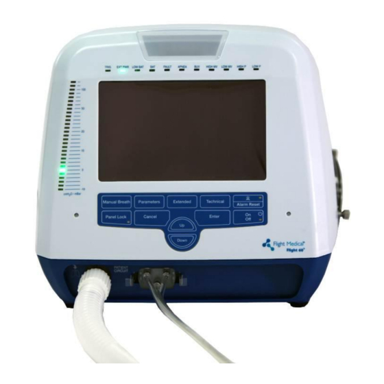
Ventilator Description Front Panel Features 3 Ventilator Description Front Panel Features The front panel contains the control buttons, visual indicators, display screen, and patient circuit connection. Figure 1 – Front Panel Label Name Description Patient Circuit Connector Composed of a gas outlet and quick connector. Up/Down button Enables the user to scroll up and down the display controls. -
Page 20: Led Indicators
Ventilator Description Front Panel Features Label Name Description Display touch screen Enables the user to modify the ventilation, alarm, and technical settings, and to view real time patient data, alarms, and logs. Inform the user of various events (see Section 3 .1.1). LED Indicators Primary Alarm LED Flashes red to indicate that there is a high priority alarm. -
Page 21: Back Panel Features
Ventilator Description Back Panel Features Back Panel Features Figure 2 – Back Panel To ensure proper grounding and prevent possible shock hazards, this device should only be connected to grounded power receptacles. HOME CAREGIVERS: External power in the home environment must support min. -
Page 22: Left Side Panel Features
Ventilator Description Left Side Panel Features Label Name Description LAN (RJ45) LAN for network logging (currently not available). Mini RS-485 (COM3) For connecting FLIGHT MEDICAL peripherals. For future use. Left Side Panel Features Figure 3 – Left Side Panel Label Name Description Emergency Air Intake... -
Page 23: Right Side Panel Features
Do not block the Fresh Gas Intake. LCD Screens The LCD screen of the FLIGHT 60 Ventilator is divided into three sections: Alarm and power management area – the top section of the screen (see Section 3 .5.1). -
Page 24: Patient Monitoring Area
Ventilator Description LCD Screens Alarms and Cautions – Left side of this area. Up to three alarms (alarm messages) and/or cautions are displayed, according to their priority. Battery icons – Right side of this area. Battery icons show: ... -
Page 25: Control Area
Ventilator Description LCD Screens Name Description Range Resolution Updated Peak Inspiratory Flow 6 to 100 L/min 1 L/min Breath by breath FiO2 Fraction of Inspired 21% to 100% O2 Every 10 seconds Oxygen Control Area 3.5.3 Parameters Screen Pressing the Parameters button switches over to the main settings screen. This is the default screen in standby and ventilation mode. - Page 26 Ventilator Description LCD Screens Button Description Used to determine the level of support in pressure during inspiration, for patient triggered spontaneous breaths. Range: 0 to 60 cmH2O/mbar Resolution: 1 cmH2O/mbar Used to set the frequency of breaths. In ACMV mode, it determines the number of time- triggered breaths;...
-
Page 27: Extended Screen
Ventilator Description LCD Screens Button Description Used to set the minimum Minute Volume allowed for a patient. LOW MV Range: 0.0 to High MV – 1 Resolution: 0.1 L Used to set the maximum Minute Volume allowed for a patient. HIGH MV Range: Low MV + 1.0 to 50 Resolution: 0.1 L... -
Page 28: Technical Screen
Ventilator Description LCD Screens Button Description Used to activate/deactivate the power saving system in the AC and DC supply. When PowerSave activated, the screen turns Off and the pressure gauge displays one LED only to indicate the peak pressure. Used to select the type of waveform: Waveform Square - the flow stays constant during the inspiratory phase Descend - the flow descends linearly until the final flow (at the end of inspiration) and is... - Page 29 Ventilator Description LCD Screens Figure 7 – Technical Settings Button Description Used to determine in which units the pressure is displayed on the ventilator. Press Units Available options: cmH2O and mbar Used to activate/deactivate the low-pressure alarm in SPONT mode. LOW P Spont Used to select the display language of the ventilator.
-
Page 30: Accessories
Ventilator Description Accessories Accessories Air/Oxygen Entrainment Mixer 3.6.1 The Air/Oxygen Entrainment Mixer is used to blend atmospheric air with medical grade oxygen at a precise ratio. A control knob allows for incremental adjustment from 21% to 100% FIO2. The high pressure oxygen hose has a standard female DISS 1240 connection. - Page 31 Ventilator Description Accessories Figure 9 - Low Pressure Oxygen Blending Bag Operator's Manual | 31...
-
Page 32: Operator's Manual
Remove all of the items from the shipping box and inspect each part and component for completeness and verify that there is no shipping damage. The complete assembly consists of the following parts: FLIGHT 60 Ventilator Operator's Manual AC Power Cord ... -
Page 33: Installing The Detachable Battery
Installation Installing the Detachable Battery 2. To mount the ventilator on the Roll Stand Assembly, follow the instructions provided with the assembly; position the ventilator on a pedestal mount and then secure it using the screws provided. Installing the Detachable Battery To install the detachable battery: 1. -
Page 34: Attaching The Patient Circuit
Installation Attaching the Patient Circuit Attaching the Patient Circuit The following procedure describes how to attach a patient circuit to the ventilator. When the complete circuit is changed. To attach the single limb patient circuit: 1. Attach the quick connector to its socket on the front panel and tightly secure. 2. -
Page 35: Installing Oxygen Accessories
7. Exhalation Valve Base Single use Exhalation Valve Diaphragm is intended for use for a maximum of 7 days. Installing Oxygen Accessories Two optional oxygen accessories can be attached to the FLIGHT 60 Ventilator: The Air/Oxygen Entrainment Mixer Operator's Manual | 35... -
Page 36: The Air/Oxygen Entrainment Mixer
4.7.1 An optional Air/Oxygen Entrainment Mixer (p/n V13-00010-60) is designed for use with the FLIGHT 60 Ventilator. It is used to blend atmospheric air with pressurized medical grade oxygen at a precise ratio. The standard oxygen inlet connection is DISS 1240. -
Page 37: Installing The Air/Oxygen Entrainment Mixer
Before attaching the Air/Oxygen Entrainment Mixer, make sure that the three hold-down screws on the Filter Cover are tight. If the screws are not tight, ambient air may enter the FLIGHT 60 Ventilator from around the inlet cover. This may change the oxygen enrichment level delivered to the patient when the Mixer is in use. -
Page 38: The Oxygen Blending Bag Kit
The Oxygen Blending Bag Kit 4.7.2 The Oxygen Blending Bag Kit is designed for use with the FLIGHT 60 Ventilator. The Oxygen Blending Bag Kit (p/n V17-00001-67) allows the operator to ventilate patients with oxygen enriched gas of up to 100% oxygen. -
Page 39: Installing The Oxygen Blending Bag Kit
Using an oxygen concentrator as the oxygen supply source may affect the level of oxygen enrichment, as in most cases oxygen concentrators do not supply 100% oxygen. Use the FLIGHT 60 Ventilator oxygen monitor to verify FiO2 delivery. Any change in settings or any change in patient assisted breathing patterns that alters the delivered minute volume, will alter the level of oxygen enrichment. -
Page 40: Disassembling And Cleaning The Oxygen Blending Bag Kit
Filter Cover are tight. If the screws are not tight, ambient air may enter the FLIGHT 60 Ventilator from around the inlet cover. This may change the oxygen enrichment level delivered to the patient when the Oxygen Blending Bag is in use. - Page 41 Installation Installing Oxygen Accessories The oxygen supply flow of the Oxygen Blending Bag Kit is determined according to the desired percent of oxygen enrichment as well as the minute volume of the patient. The oxygen blending bag is not a calibrated oxygen mixing device. It requires the use of oxygen monitoring, to verify the level of oxygen enrichment.
- Page 42 Installation Installing Oxygen Accessories Figure 21 - Oxygen Supply Flow for Desired % of Oxygen Enrichment with PEEP 42 | Flight 60...
-
Page 43: Using The Ventilator
Review all of the General Warnings and Cautions in Chapter 2 prior to using the ventilator. The FLIGHT 60 Ventilator can be used either with an AC (external) or DC (internal batteries) power source. Before using the ventilator, either with AC or DC power source, ensure that the internal batteries are fully charged. -
Page 44: Turning Off The Ventilator
Using the Ventilator Basic Operation Turning Off the Ventilator 5.1.2 To shut down the ventilator: 1. On the ventilator front panel, press the On/Off button. The system pops up a message: “Are you sure you want to shut down? To shut down, press the On/Off button for 3 seconds ". -
Page 45: Default And Saved Values
Using the Ventilator Basic Operation Press Enter. Press another control button to select a new parameter for adjustment. Wait five seconds without making a change. Default and Saved Values When the device is brought up for the first time, it uses a set of default values for all of its parameters and settings. -
Page 46: Canceling Parameter Adjustments
Using the Ventilator Setting the Main Parameters The LED turns on. All buttons are disabled for adjustment, except for the Audio Paused/Alarm Reset button. To unlock the panel: Press the Panel Lock button once and then press the Enter button. The Panel Lock button is deactivated. -
Page 47: Simv Mode (Synchronized Intermittent Mandatory Ventilation)
Using the Ventilator Setting the Main Parameters As with all FLIGHT 60 Ventilator operating modes, Backup Ventilation is activated if the Apnea alarm limit is violated. In A/CMV mode, the PSV, PSV Flow Term and PSV Ti control buttons are not utilized and are therefore darkened. -
Page 48: Spont Mode (Spontaneous Ventilation)
Entries for tidal volume, f and Ti are all inactive in SPONT mode. However, users can preset these parameters for future ACMV or SIMV operation. As with all FLIGHT 60 Ventilator operating modes, Backup Ventilation is activated if the Apnea alarm limit is violated. -
Page 49: Volume Control Ventilation (Vcv)
Using the Ventilator Setting the Main Parameters In either case, all breaths delivered to the patient, whether time (ventilator initiated) or patient-triggered, are the same. In SPONT mode, the PCV/VCV button is not utilized and is therefore darkened; however, the value can be preset. Volume Control Ventilation (VCV) The user can define which parameter will remain constant when changing the VCV –... - Page 50 Using the Ventilator Setting the Main Parameters To set the VCV submode of operation: 1. Tap the PCV/VCV control button. The PCV and VCV submodes are displayed. Figure 24 – Available Submodes 2. Tap the VCV option. VCV appears on the VCV/PCV button. The VCV control button appears on the Parameters screen, with its predefined numerical value.
-
Page 51: Pressure Control Ventilation (Pcv)
Using the Ventilator Setting the Main Parameters Pressure Control Ventilation (PCV) The FLIGHT 60 Ventilator targets and maintains patient airway pressure at the set pressure control level throughout inspiration. Breath termination occurs when either of the following conditions exists: The set Ti elapses. -
Page 52: Inspiratory Time (Ti) / Flow
Using the Ventilator Setting the Main Parameters To set the PCV submode of operation: 1. Tap the PCV/VCV control button. The PCV and VCV submodes are displayed. Figure 26 – Available Submodes 2. Tap the PCV option to select it. PCV appears on the PCV/VCV button. -
Page 53: Inspiratory Time
Using the Ventilator Setting the Main Parameters The Flow and Ti values are related to each other. Therefore, if the Ti setting causes the flow rate to reach the maximum or minimum level of the flow specification, you cannot further change the Ti numeric value, and a setting limitation message appears in a popup window. -
Page 54: Frequency Of Breaths (F)
Using the Ventilator Setting the Main Parameters Figure 29 – Setting the Mandatory Flow Frequency of Breaths (f) 5.2.4 In the ACMV mode, the f (frequency) setting determines the minimum number of time-triggered mandatory breaths; in the SIMV mode, it determines the total number of mandatory breaths. -
Page 55: Positive End Expiratory Pressure (Peep)
Using the Ventilator Setting the Main Parameters Figure 31 – Setting the Pressure Trigger Level It is recommended to set Ptrig as close to -0.1 cmH2O as possible without auto triggering, in order to maximize triggering synchrony. Positive End Expiratory Pressure (PEEP) 5.2.6 The PEEP setting establishes a baseline positive airway pressure in the patient circuit during the exhalation phase. -
Page 56: Lower And Upper Pressure Limits (Low P, High P)
Using the Ventilator Setting the Main Parameters Breaths are terminated when any of the following conditions exists: The flow to the patient drops to the set % of that breath's peak flow. The target airway pressure is exceeded by 3 cmH2O (mbar). ... -
Page 57: Lower And Upper Minute Volume Alarm Limits (Low Mv, High
Using the Ventilator Setting the Main Parameters Figure 34 – Setting the Low Pressure Limit If the system detects that the pressure does not reach the Low P settings for three consecutive mandatory breaths, the Low Pressure alarm is activated. This alarm becomes passive when even one of the mandatory breaths reaches the requested level. -
Page 58: High Mv
Using the Ventilator Setting the Main Parameters Figure 36 – Setting the Low Minute Volume Alarm Limit If the patient inspiratory or expiratory minute volume drops below the Low MV set value, an alarm sounds and a message is displayed. High MV To set the High MV value: 1. -
Page 59: Setting The Extended Parameters
Using the Ventilator Setting the Extended Parameters Message Activation LOW P Limited by PEEP LOW P reached PEEP + 3. PCV Limited by PEEP PCV reached PEEP + 5. Reached Max Flow Increasing VCV or Decreasing Ti caused the Flow to reach its max possible value. -
Page 60: Waveform Type
Using the Ventilator Setting the Extended Parameters control buttons were touched or alarms were set off the screen turns Off and the pressure gauge displays one LED only to indicate the peak pressure. To activate/deactivate the power saving system: 1. On the ventilator front panel, press the Extended button. The Extended parameters are displayed on the ventilator screen. -
Page 61: Inspiratory Time / Flow Control (Ti / Flow Ctl.)
Using the Ventilator Setting the Extended Parameters The Extended parameters are displayed on the ventilator screen. 2. Tap the Waveform control button. The control button turns orange, and a pop-up list displays the two options: Square and Descend. 3. Tap the control button to select Square or Descend. Your selection is displayed on the control button. -
Page 62: Pressure Support Flow Termination (Psv Flow Term)
Using the Ventilator Setting the Extended Parameters Figure 39 – The Fastest Rise Profile (Level 1) Figure 40 – The Slowest Rise Time (Level 5) To set the rise profile level: 1. On the ventilator front panel, press the Extended button. The Extended parameters are displayed on the ventilator screen. -
Page 63: Pressure Support Ventilation Inspiratory Time (Psv Ti)
Using the Ventilator Setting the Extended Parameters 2. Tap the PSV Flow Term control button. The control button turns orange. 3. Press the Up/Down button soft key to increase/decrease the threshold in steps of 5, until you reach the desired flow threshold. The selected flow threshold is displayed on the control button. -
Page 64: High And Low Levels For The Oxygen Alarm (Fio2 Low And Fio2 High)
Using the Ventilator Setting the Extended Parameters 3. To activate monitoring tap the button ON; to deactivate monitoring tap the button OFF. High and Low Levels for the Oxygen Alarm (FiO2 Low and FiO2 High) The system sets off an alarm when there is a low and/or a high level of oxygen in the ventilator air mixture. -
Page 65: Backup Ventilation In Acmv And Simv Modes
Using the Ventilator Setting the Extended Parameters The Extended parameters are displayed on the ventilator screen. 2. Tap the Apnea control button. The control button turns orange. 3. Press the Up/Down button soft key to increase/decrease the value of the Apnea. The selected value is displayed on the button. -
Page 66: Setting The Technical Parameters
Using the Ventilator Setting the Technical Parameters Backup Ventilation is not active for the Apnea preset time after the user resets the BUV alarm. Setting the Technical Parameters System Language 5.4.1 You can select the language of the ventilator display. To set the system language: 1. -
Page 67: Displaying The System Information
Using the Ventilator Setting the Technical Parameters To deactivate the low pressure alarm: 1. On the ventilator front panel, press the Technical button. The Technical parameters are displayed on the ventilator screen. 2. Tap the LOW P Spont control button. The control button turns orange, and a pop-up list displays the two options: ON and OFF. -
Page 68: Storing/Loading A Ventilation Configuration
Some disposable patient circuit/exhalation valve assemblies are not compatible with the FLIGHT 60 Ventilator due to the requirements of the ventilator's pressure management system. If your disposable circuit fails consistently,... -
Page 69: System Clock
Using the Ventilator Setting the Technical Parameters To load a predefined ventilation configuration: 1. On the ventilator front panel, press the Technical button. The Technical parameters are displayed on the ventilator screen. 2. Tap the Set Load control button. The control button turns orange, and a pop-up list with the numbers of the saved configurations appears. -
Page 70: Accessing The Advanced Technical Menu
Using the Ventilator Initiating Ventilation You can scroll through the list of alarms, using the Up/Down button. When prompted, you can clear the log from the screen by confirmation. The code is 1315. Changes to the ventilator are logged by date, time, type, and values. You can browse through the log, to see changes that have been made to the ventilator states, modes, and settings. -
Page 71: Monitoring The Patient
Using the Ventilator Monitoring the Patient 3. Reassess HIGH Pressure and LOW Pressure alarm settings, and adjust them to appropriate levels. 4. Verify that the Ptrig indicator blinks each time the patient initiates a spontaneous inspiratory effort. Readjust Ptrig as necessary. 5. -
Page 72: Ventilator Alarms
Audible Alarm and Caution Signals 6 Ventilator Alarms The FLIGHT 60 Ventilator comes with an intelligent alarm system, which warns you of problems with the ventilator. An alarm occurs when there is a risk to the patient. A caution occurs when there is an undesirable situation which does not pose immediate risk to the patient. -
Page 73: Alarm And Caution Specifications
Contact your provider or FLIGHT MEDICAL. Alarm and Caution Specifications This section describes the specifications for the FLIGHT 60 Ventilator: Variable ventilation alarms Automatic ventilation alarms Automatic technical alarms ... -
Page 74: Automatic Ventilation Alarms
Ventilator Alarms Alarm and Caution Specifications Alarm Range Activation LOW MV INS 0.0 to 50.0 L/min When the inspiratory or expiratory minute volume falls below the Low Minute Volume alarm setting LOW MV EXH HIGH MV INS 1.0 to 50.0 L/min When the inspiratory or expiratory minute volume exceeds the High Minute Volume alarm setting HIGH MV EXH... -
Page 75: Cautions
Ventilator Alarms Silencing Audible Alarms Alarm Activation MEMORY FAULT When the NVRAM does not work properly CHECK SETTING When the self test finds that settings parameters are out of range Main BAT CHARGER When the detachable (main) battery charger does not start working Main BAT V. -
Page 76: Resetting Alarms
Ventilator Alarms Resetting Alarms To silence audible alarms and cautions: 1. On the ventilator front panel, press the Audio Paused button. The system enters pre-silence mode. The Audio Paused indicator is illuminated, and all alarms (except for the Fault Alarm) are silenced for 60 seconds. You can cancel the pre-silence mode before 60 seconds are up, by pressing the Audio Paused button once again. -
Page 77: Cleaning And Maintenance
Homecare Dealer instructions. FLIGHT 60 Ventilator 7.1.1 Wipe clean the FLIGHT 60 Ventilator between patients, and once a week while in use. To clean the ventilator: 1. Wipe clean the exterior (besides the screen) of the ventilator and all parts not in direct contact with patients, using a cloth that has been dampened with a medical detergent or alcohol-based cleaning solution. -
Page 78: Oxygen Blending Bag Kit
Oxygen Blending Bag Kit To disassemble the Oxygen Blending Bag Kit: 1. Remove the Oxygen Blending Bag Kit from the FLIGHT 60 Ventilator air inlet. 2. Disconnect the oxygen tubing and slide the rubber bag off its fitting. To clean the Oxygen Blending Bag Kit: 1. - Page 79 Cleaning and Maintenance Cleaning and Disinfecting Examine the patient circuit for excessive wear or damage. Discard and replace, if necessary. To avoid degradation of the reusable (single patient) patient circuit components, do not exceed 20 cleaning cycles or half a year of usage (whichever occurs first).
-
Page 80: Reusable (Single Patient) Exhalation Valve
Cleaning and Maintenance Cleaning and Disinfecting 3. Air dry. Patient circuit components should NOT come in contact with the following solutions, because they may cause disintegration of the tubing: Hypochlorite, Phenol (>5%), Inorganic Acids, Formaldehyde, Ketone, Chlorinated Hydrocarbons, and Aromatic Hydrocarbons. Patient circuits should be inspected after disinfecting to check for deterioration. - Page 81 Cleaning and Maintenance Cleaning and Disinfecting To clean the exhalation valve: 1. Use a low flow of running water or air to clear tubing and passages of organic matter. 2. Wash the exhalation valve with a soft brush. 3. Rinse thoroughly with sterile, distilled water. 4.
-
Page 82: Flight 60 Ventilator Air Inlet Particle Filter
Cleaning and Maintenance Maintenance FLIGHT 60 Ventilator Air Inlet Particle Filter NEVER operate the FLIGHT 60 Ventilator without a clean inlet particle filter in place. NEVER reverse the inlet particle filter when it is dirty. The air inlet particle filter, located on the right side of the ventilator behind the Filter Cover, keeps dirt and particles out of the ventilator's piston system. -
Page 83: Internal Battery Maintenance
Maintenance NEVER reverse the inlet particle filter when it is dirty. Inspect the FLIGHT 60 Ventilator power cord on a regular basis, for signs of a broken or frayed power cord. Inspect the exhalation valve and flow orifice to verify that there are no cracks or damaged surfaces. -
Page 84: General Warnings
Cleaning and Maintenance General Warnings General Warnings Preventive maintenance work, repairs, and service may only be performed by FLIGHT MEDICAL trained or factory-authorized personnel. Always follow accepted hospital procedures or physician instructions for handling equipment contaminated with body fluids. ... -
Page 85: Troubleshooting
The following practical troubleshooting section is provided as a training resource for individuals learning how to use the FLIGHT 60 Ventilator, and as a reference tool for those already familiar with its use and operation. It should be noted that this outline is not all inclusive, and is intended only as a guide. - Page 86 Troubleshooting Alarms Problem Potential Cause Suggested Action Proximal line disconnected or kinked. Reconnect the proximal line or unkink the line. Circuit is disconnected from the Reconnect the circuit to the patient. patient. Quick connector is loosened. Secure the quick connector. Pressure transducer is improperly Call FLIGHT MEDICAL.
- Page 87 Troubleshooting Alarms Problem Potential Cause Suggested Action Increase in trachea/airway leak. Evaluate the leak, look for normal wake- sleep trends, and set alarms appropriately. Increased minute volume due to Check circuit for leak and correct. ventilator auto triggering from leak Perform leak check (exhalation valve calibration) on patient circuit.
-
Page 88: General/Clinical
Troubleshooting General/Clinical Problem Potential Cause Suggested Action Patient needs suctioning or airway Suction and evaluate patient. occlusion (pressure control / pressure support). Patient is breathing slowly or is not Evaluate patient. breathing. Apnea interval is too short. Evaluate the patient. Adjust the Apnea alarm. - Page 89 Troubleshooting General/Clinical Problem Potential Cause Suggested Action Batteries are not fully charged. Charge the batteries to their full Batteries depleted too charge level. Batteries charge in three fast; not lasting up to hours from AC. Check the charge level 12 hours by viewing the main and secondary battery icon level on the display.
- Page 90 Troubleshooting General/Clinical Problem Potential Cause Suggested Action Low Pressure alarm is not Set the Low Pressure alarm to ensure Circuit disconnect / no appropriately set. that it sounds when the patient circuit alarm sounds is disconnected. After setting up the Patient circuit is patient and stabilizing the ventilation, disconnected from...
- Page 91 Troubleshooting General/Clinical Problem Potential Cause Suggested Action Power cord is not plugged far enough Check that the power cord is pushed in External Power Not into the ventilator outlet. all the way. Working After plugging into an AC outlet has no power. Check for power in the AC outlet or use external AC or DC another AC outlet with power.
- Page 92 Troubleshooting General/Clinical Problem Potential Cause Suggested Action Patient circuit resistance is caused by Temporarily disconnect the patient Pressure reading an occluded filter or exhalation valve, circuit from the ventilator GAS OUTPUT Pressure does not pooled water, or lodged secretions outlet. If the pressure reading returns return to zero when which prevent the free exit of patient to zero, the cause of the elevated...
-
Page 93: Air/Oxygen Entrainment Mixture
Air Oxygen Entrainment Mixer connected to a gas cylinder. The FLIGHT 60 Ventilator generates a Ventilator is operating correctly. Ventilator Pistons 7.5 L/min of continuous flow in Move Between Breaths between breaths when PEEP is > 0 Ventilator sounds like cmH2O. -
Page 94: Contact Information
Mixer when MEDICAL. connected to 50 psig oxygen gas source. Contact Information Address further questions or problems to one of the FLIGHT MEDICAL offices. FLIGHT MEDICAL INNOVATIONS Ltd. Address: 13 Hamelacha St., Lod 71520, ISRAEL Tel: +972-8-923-5111 Fax: +972-8-923-6111 Email: info@flight-medical.com... -
Page 95: Ventilator Quick Check Procedure
Checking the monitored parameters HOME CAREGIVERS: This procedure should be performed by your Homecare equipment provider, prior to delivery of the FLIGHT 60 Ventilator, to verify proper operation. It can also be performed in the homecare environment to ensure proper setup and function of the ventilator. -
Page 96: Quick Check Procedure
1. Connect the detachable and Integral batteries. 2. Connect the AC power cord to an AC power source. 3. Connect a patient circuit with 500 ml test lung, to the FLIGHT 60 Ventilator. 4. Calibrate the exhalation valve See Section 5 .4.5. -
Page 97: Checking The Alarms
Ventilator Quick Check Procedure Quick Check Procedure 3. Verify that the arrows on the batteries icons facing down to indicate that the batteries are depleted. 4. Disconnect the detachable battery. Verify that there is a Low Battery caution message and intermittent audible caution. 5. -
Page 98: Check-Off Sheet
Ventilator Quick Check Procedure Check-Off Sheet Check-Off Sheet FLIGHT 60 Ventilator Quick Check Pass/Fail Check-Off Sheet Preparation for Use Tests Indicate Result for each Test Pretest Inspection Check Pass _____ Fail ______ 1. Power Management Check Pass _____ Fail ______... -
Page 99: Technical Specifications
Technical Specifications Physical Specifications 10 Technical Specifications 10.1 Physical Specifications Physical Characteristic Specification Ventilator Weight 6.3 kg 11.641 in wide x 11.457 in deep x 9.803 in high Ventilator Dimensions 295 mm wide x 291 mm deep x 249 mm high Reusable Single Patient Reusable (single patient) 22 mm ID 180 cm. -
Page 100: Internal Battery Specifications
Technical Specifications Internal Battery Specifications 10.4 Internal Battery Specifications Battery Characteristic Specification Detachable Battery Battery Type Li-Ion Nominal Voltage 14.8 VDC Nominal Pack Capacity 5.2 AH Charging Time Three hours MAX Integral Battery Battery Type Li-Ion Nominal Voltage 14.8 VDC Nominal Pack Capacity 2.6 AH Charging Time... -
Page 101: Environmental Specifications
Technical Specifications Environmental Specifications 10.6 Environmental Specifications Condition Range Operating Temperature C to 50 C / -.4 F to 122 Storage Temperature C to 60 C / -5.8 F to 160 Operating Pressure (Altitude) 70 KpA to 110 KpA Humidity 15% to 95% RH at 31 Water Resistance IP34 (splash proof) IEC 60529...
Need help?
Do you have a question about the Flight 60 Ventilator and is the answer not in the manual?
Questions and answers