
Subscribe to Our Youtube Channel
Related Manuals for Flight Medical Innovations FLIGHT 60T


Summary of Contents for Flight Medical Innovations FLIGHT 60T
- Page 1 FLIGHT MEDICAL INNOVATIONS LTD. FLIGHT 60T Turbine Ventilator Operator's Manual March 2024 LIT-0089 Rev.B14 OPERATING MANUAL-FLIGHT60 TURBINE SYMBOL KEYPAD WITH OPTIONAL INTERNAL O2 MIXER SW 5.38...
-
Page 3: Legal Notice
When the FLIGHT 60T Ventilator is used in homecare, hospitals, EMS and sub- acute environments, only properly trained personnel should operate the ventilator. The FLIGHT 60T Ventilator is a restricted medical device designed... -
Page 4: Warranty
FLIGHT MEDICAL due to such situations. Warranty The FLIGHT 60T Ventilator warranty does not apply for/ in case of: Defects caused by misuse, mishandling, tampering, or by modifications not authorized by FLIGHT MEDICAL or its representatives. -
Page 5: About This Document
About this Document About this Document This document contains information intended to ensure safe and effective use of the FLIGHT 60T Ventilator. Chapter Name Contents Page Introduction Describes the intended use of the ventilator, symbols Pg. 1-1 appearing on the ventilator, and an overview of how the ventilator works. - Page 6 About this Document Chapter Name Contents Page Ventilator Quick Check Describes the testing procedures. Pg. 15-1 Procedure Technical Specifications Describes the technical specifications for: hardware, Pg. 16-1 safety, environmental and oxygen accessories. Operator's Manual | iv...
-
Page 7: Table Of Contents
Table of Contents Table of Contents INTRODUCTION ................. 1-1 ................1-1 NTENDED ..................1-1 YMBOLS SAFETY INSTRUCTIONS ..............2-1 ................. 2-1 ENERAL ARNINGS ..................2-5 AUTIONS ................. 2-6 ONTRAINDICATIONS VENTILATOR DESCRIPTION ............... 3-1 ..............3-1 RONT ANEL EATURES 3.1.1 Control Buttons ..............3-2 3.1.2 LED Indicators .............. - Page 8 Table of Contents .............. 6-1 ARAMETERS CREEN 6.1.1 Pop-Up Messages ..............6-6 ................6-8 XTENDED CREEN ................6-9 LARMS CREEN ..............6-11 PNEA ACKUP CREEN ................6-12 ECHNICAL CREEN VENTILATOR ALARMS AND BACKUP VENTILATION ......7-1 ................7-1 UDIBLE LARMS ..............
- Page 9 12 CLEANING AND MAINTENANCE ............12-1 12.1 C ............. 12-1 LEANING AND ISINFECTING 12.1.1 FLIGHT 60T Ventilator ............12-1 12.1.2 FLIGHT 60T Ventilator Accessories ........12-1 12.2 M ................12-3 AINTENANCE 12.2.1 Preventive Maintenance ............12-3 12.2.2 O Sensor Maintenance ............12-4 12.2.3 Internal Battery Maintenance ..........
- Page 10 Table of Contents 15.2.2 Checking the Alarms............15-3 15.2.3 Checking the Monitored Parameters ........15-3 15.3 C ................15-4 HECK HEET 16 TECHNICAL SPECIFICATIONS ............16-1 16.1 P ..............16-1 HYSICAL PECIFICATIONS 16.2 P ............... 16-1 NEUMATIC PECIFICATIONS 16.3 E .
-
Page 11: Introduction
(i.e., infant, child and adolescent) patients who weigh at least 5 kg (11 lbs). The FLIGHT 60T Ventilator is a restricted medical device intended for use by qualified, trained personnel under the direction of a physician; it is suitable for use in hospitals, sub-acute emergency rooms, and home care environments, as well as for transport and emergency response applications. - Page 12 Introduction Symbol Description Alarm Mute/Reset Alarm off* OK (Enter) Decrease Button Increase Button Cancel Panel Lock Manual Breath Parameters Screen Extended Screen Technical Screen Nebulizer Port (optional) Caution; consult accompanying documents Type BF applied part Temperature limitation Humidity limitation Atmospheric pressure limitation Operator's Manual | 1-2...
- Page 13 Introduction Symbol Description DC – Direct Current AC – Alternating Current USB – Universal Serial Bus LAN – Local Area Network High Pressure (optional) and Low-Flow Oxygen Port USA Federal Law restricts this device to sale by or on the order of a Physician Keep sensitive magnetic susceptible electronic and storage devices 15 cm (6 in) from ventilator.
-
Page 15: Safety Instructions
Safety Instructions 2 Safety Instructions At all times, strictly follow this manual. The safe use of the FLIGHT 60T Ventilator requires full understanding of its operation, and adherence to the manual's instructions. The equipment is only to be used for the purpose specified in Section 1.1. - Page 16 Always use appropriate monitors to ensure sufficient oxygenation and ventilation (such as pulse oximeter and/or capnograph) when the FLIGHT 60T Ventilator is in use on a patient. If a fault is detected in the ventilator and its life support functions are in doubt, immediately discontinue use;...
- Page 17 This depends on a number of factors including settings and usage patterns. When the FLIGHT 60T Ventilator is used for transport applications, ensure that the internal batteries are fully charged prior to use.
- Page 18 Safety Instructions Always plug the FLIGHT 60T Ventilator into an AC power supply source when not in use, to ensure best battery performance. The flow resistance of the air inlet filter, located on the right side of the ventilator, is likely to increase with repeated use.
-
Page 19: Cautions
Only use medical grade oxygen with the high- and low- pressure ports. Do not place liquid containers in the immediate vicinity or on top of the FLIGHT 60T Ventilator. Liquids that get into the ventilator can cause equipment malfunction and damage. -
Page 20: Contraindications
Use the tools and equipment specified in this manual to perform specific procedures. Contraindications The FLIGHT 60T is not intended for patients who weigh less than 5 kg To prevent possible patient injury, do NOT use noninvasive ventilation on patients with no or irregular spontaneous breaths. Noninvasive ventilation is intended to provide supplemental ventilatory support to patients with regular spontaneous breaths. -
Page 21: Ventilator Description
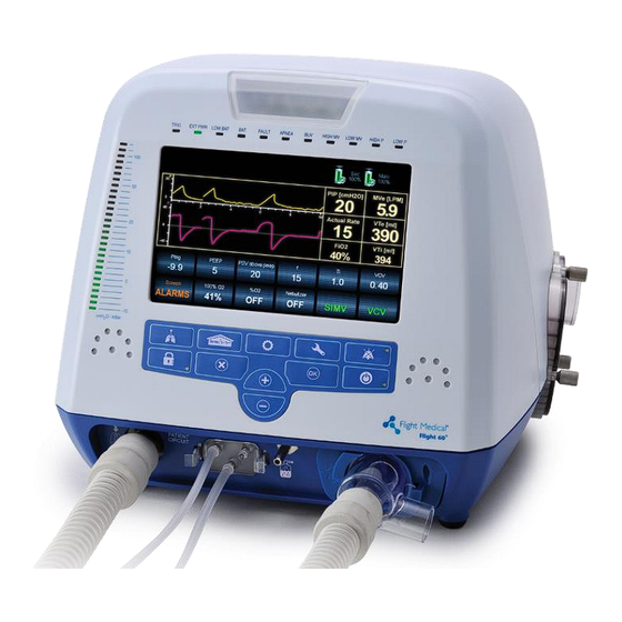
Ventilator Description 3 Ventilator Description Front Panel Features The front panel contains the control buttons, visual indicators, display screen, and patient circuit connection. Figure 1 – Front Panel Label Name Description Patient Circuit Connector Composed of a gas outlet and quick connector. +/- button Enables the user to adjust setting parameters. -
Page 22: Control Buttons
Item Symbol Description 1 – Parameters The Parameters screen is the FLIGHT 60T's default screen. (home) Display switches automatically to Parameters from the other screens if not operated for 30 seconds. Use the Parameters button to toggle between the graphic and the numeric/homecare display. -
Page 23: Led Indicators
Ventilator Description Item Symbol Description 4 – Cancel Enable the user to cancel parameters change. 5 – Increase Enables the user to adjust setting parameters upwards. Button 6 – Decrease Enables the user to adjust setting parameters downwards. Button 7 – OK (Enter) Enable the user to confirm parameters or mode change. -
Page 24: Back Panel Features
Ventilator Description Back Panel Features Figure 3 – Back Panel To ensure proper grounding and prevent possible shock hazards, this device should only be connected to grounded power receptacles. HOME CAREGIVERS: External power in the home environment must support min. 100 to max. 240 V AC, and must have a grounded receptacle. -
Page 25: Left Side Panel Features
Ventilator Description Label Name Description RS-232 Serial Port (COM1) Online output of events and error messages to the PC, using a dedicated PCS2 protocol; for authorized and qualified service technicians only. USB B type PC connector: USB port for downloading the main application from the PC using a dedicated PCS2 protocol;... -
Page 26: Right Side Panel Features
Cover to protect the patient as well as the ventilator’s piston system from dirt and particles. The Fresh Gas Intake also serves as the attachment socket for the optional FLIGHT 60T Ventilator Air/Oxygen Entrainment Mixer. Do not block the Fresh Gas Intake. -
Page 27: Installation
The complete assembly consists of the following parts: FLIGHT 60T Ventilator AC Power Cord Patient Circuit – Single Patient Use Air Inlet Filter (pk. Of five filters) ... -
Page 28: Installing The Detachable And Integral Batteries
Installation Installing the Detachable and Integral Batteries To install the detachable battery: 1. Insert the detachable battery into the ventilator. 2. Turn the lock dial clockwise, in the direction of the CLOSE arrow, until it is firmly locked. Figure 6 – Installing the Detachable Battery To install the integral battery: 1. -
Page 29: Connecting The Patient Circuit
The following procedure describes how to attach a patient circuit to the ventilator. Only a FLIGHT MEDICAL approved patient circuit can be used with the FLIGHT 60T Ventilator. 4.6.1 Connecting a Dual limb patient circuit 1. Connect the quick connector to the ventilator proximal connection ports on the front panel and tightly secure. -
Page 30: Connecting A Single Limb Patient Circuit
Installation 4.6.2 Connecting a single limb patient circuit 1. Connect the quick connector to the ventilator proximal connection ports on the front panel and tightly secure (a single limb flow sensor consist of 3 silicon tubes). 2. Connect the inspiratory limb to the gas outlet on the front panel. 3. -
Page 31: Heated Wire Circuit With A Humidifier
1. Connect an adult (500 ml) test lung with a 90 degree elbow to the Flow Sensor's patient side or to the HME, if used. 2. Press the On/Off button once to place the FLIGHT 60T into standby mode (the FLIGHT 60T displays are on, but ventilation has not been initiated). -
Page 32: Hfot (High Flow Oxygen Therapy) Setting
Installation Outlet Humidifier Flow sensor Quick connector Proximal connection Heated inspiratory limb Exhalation valve port with temperature sensor, to patient HME Filter Flow sensor Inspiratory limb to Heated expiratory limb humidifier 4.6.5 HFOT (High Flow Oxygen Therapy) Setting Operator's Manual | 4-6... - Page 33 Installation Flight Medical flow sensor must be used when using HFOT mode. 1. Connect the flow sensor to the ventilator outlet port. 2. Connect the non-heated circuit to the flow sensor and to one of the humidifier ports. 3. If using with an HME, attach the HME at the outlet port. 4.
-
Page 34: Connecting The Oxygen Supply
Installation Outlet Flow sensor Heated inspiratory limb with temperature sensor, to patient Proximal Inspiratory limb to HFNC connection port humidifier HME Filter Humidifier Flow sensor Quick connector Connecting the Oxygen Supply Oxygen enrichment can come from high- or low-pressure source with the following options: Operator's Manual | 4-8... -
Page 35: Internal O Mixer
External Air/Oxygen Entrainment Mixer An optional Air/Oxygen Entrainment Mixer (p/n V13-00010-60) is designed for use with the FLIGHT 60T Ventilator. It is used to blend atmospheric air with pressurized medical grade oxygen at a precise ratio. The standard oxygen inlet connection is DISS 1240. - Page 36 Set the trigger to be comfort to the patient, without auto triggering. No oxygen is delivered through the Air/Oxygen Entrainment Mixer while the FLIGHT 60T Ventilator is in Standby or Settings mode. Figure 8 – Air/Oxygen Entrainment Mixer Operator's Manual | 4-10...
- Page 37 4. With the oxygen hose facing toward the front of the ventilator, press the 30 mm OD outlet of the Mixer into the Attachment Socket (Fresh Gas Intake port) of the FLIGHT 60T Ventilator Filter Cover. Rotate the mixer 1/4 turn clockwise to secure it into place.
-
Page 38: Low-Flow Oxygen Port
Installation Ensure that the oxygen supply is enabled prior to powering on the FLIGHT 60T Ventilator and after the Air/Oxygen Entrainment Mixer is secured in place. Otherwise, stress to the internal pump will occur and gas delivery to the patient will be compromised. - Page 39 Installation I:E Ratio Leak Rate Low Pressure Oxygen Flow Rate When oxygen is administrated with a low flow source the actual delivered oxygen concentration will vary. Substantial leaks may reduce the inspired oxygen concentration. FiO should be monitored and appropriate alarm settings should be used.
-
Page 41: Basic Operation
Review all of the General Warnings and Cautions in Chapter 2 prior to using the ventilator. The FLIGHT 60T Ventilator can be used either with an AC (external) or DC (internal batteries) power source. Before using the ventilator, either with AC or DC power source, ensure that the internal batteries are fully charged. -
Page 42: Initiating Ventilation
Basic Operation Initiating Ventilation After setting all the required parameters, checking all alarm limit and control settings to ensure that they are appropriate for the patient to be ventilated, and performing circuit test, you can initiate ventilation. To begin ventilation: 1. -
Page 43: Navigating Between Screens
Basic Operation The ventilator can be turned off only from the setting mode. If the ventilator ventilating, you must stop ventilation and then proceed to shut down. When operating with a battery and turning off the ventilator from SETTINGS mode, Press the Mute button to mute the audible alarm. -
Page 44: Default And Saved Values
Basic Operation To adjust non-numeric control values: 1. Select the parameter by pressing the relevant control button (for example: mode selection button). The control button's color changes from grey to orange, indicating that its value is enabling for adjustment. 2. Tab the screen to toggle the value. 3. -
Page 45: Ventilator Settings
Ventilator Settings 6 Ventilator Settings Home (Parameters) Screen This is the default screen in standby and ventilation mode. The display always switches back automatically to Parameters from the Extended or Technical settings display. Pressing the Parameters button switches over to the main settings screen. - Page 46 Ventilator Settings Button Description Rate Used to set the frequency of breaths. In ACMV mode, it determines the number of time- triggered breaths; in SIMV mode, it determines the total number of mandatory breaths. If the selected Rate setting results in an inverse I:E Ratio, the system displays an “Inverse I:E”...
- Page 47 O/mbar. Ptrig The Flight 60T provides pressure or flow based triggering. Used to determine the pressure trigger level (trigger sensitivity) in terms of how far the airway pressure must drop below the set baseline pressure in order for a patient's spontaneous efforts to be detected.
- Page 48 Ventilator Settings Button Description PS above Used to determine the level of support in pressure during inspiration, for patient triggered PEEP spontaneous breaths in SIMV, SPONT, VtG, MVG and B-LEVEL modes. During each spontaneous breath, the ventilator supports the patient by elevating the airway pressure to the PSV above peep + PEEP level.
- Page 49 Ventilator Settings Button Description P Low Used to set the low pressure baseline in B-LEV mode. Range: 0 to 40 cmH2O/mbar Resolution:1 cmH2O/mbar The value of P Low plus PS above PEEP cannot exceed 60 cmH O/mbar. The value of P Low cannot exceed the P High value. P High Used to set the high pressure baseline in B-LEV mode.
-
Page 50: Pop-Up Messages
Ventilator Settings Button Description HIGH MV Used to set the maximum Minute Volume allowed for a patient. Range: Low MV + 1.0 to 50 Resolution: 0.1 L ALARMS Used to open the Alarms Screen 6.1.1 Pop-Up Messages The following table lists the pop-up messages, and how they are activated. Message Reason PEEP is limited by PC... - Page 51 Ventilator Settings Message Reason Max Ti reached Increasing VCV or Decreasing Flow caused Ti to reach its max possible value. Min Ti reached Decreasing VCV or increasing Flow caused Ti to reach its min possible value. LOW O is limited by HIGH O LOW O reached HIGH O –...
-
Page 52: Extended Screen
Ventilator Settings Message Reason Cannot start O2 calibration when O2 calibration is not available when Nebulizer is ON nebulizer is ON LOW MVe alarm is disabled! When NIV is set to ON the Low MVe alarm is disabled VT was updated due to Flow In VCV only: When the set VT do not correspond the set Ti limitations Cannot start Circuit Test due to low... -
Page 53: Alarms Screen
Ventilator Settings Button Description Used to activate the MVG trigger delay function. Trigger Delay OFF: Trigger delay function is disabled. ON: Doubles the delay time before mandatory (time cycled) ventilation is activated. Used to set the rise level that the system will deliver. Rise Profile Available levels are 1 (fastest) to 5 (slowest). - Page 54 Ventilator Settings Button Description Buzzer Used to set the alarm buzzer volume. Available options: HIGH and LOW APNEA Used to open the Apnea Backup Screen BACKUP LOW P Used to set the minimum allowed pressure of a mandatory breath. Range: 1 to HIGH P Resolution:1 cmH O/mbar HIGH P...
-
Page 55: Apnea Backup Screen
Ventilator Settings Button Description Apnea Used to set the maximum allowed time of apnea. Interval Range: 10 to 60 seconds Resolution: 10 seconds Apnea Backup Screen Pressing the Apnea Backup button switches over to the Apnea Backup (BUV) settings screen. Figure 16 –... -
Page 56: Technical Screen
Ventilator Settings Technical Screen Pressing the Technical button switches over to the technical settings screen. Figure 17 – Technical Settings Button Description Used to perform in-use O calibration and activate or deactivate O monitoring. FiO2 Sensor Activating FiO displays the FiO value on the screen;... - Page 57 Ventilator Settings Button Description This button replaces "Circuit TEST" button during ventilation. Maneuver Enabled during ventilation. ON/OFF Used to load a ventilation configuration that has been predefined in the ventilator. Set Load Used to save a ventilation configuration in the ventilator, for later use. Up to five Set Save configurations can be saved.
-
Page 59: Ventilator Alarms And Backup Ventilation
7 Ventilator Alarms and Backup Ventilation The FLIGHT 60T Ventilator comes with an intelligent alarm system, which warns you of problems with the ventilator. An alarm occurs when there is a risk to the patient. A caution occurs when there is an undesirable situation which does not pose immediate risk to the patient. -
Page 60: Visual Alarms Signals
Ventilator Alarms and Backup Ventilation The caregiver can select the alarm sound level between high/low. Visual Alarms Signals The visual alarm system is composed of: One major visual alarm signal – Flashing red led to indicate that there are alarms in the system. Type of flashing indication: High Priority Alarms –... -
Page 61: Alarm Specifications
Ventilator Alarms and Backup Ventilation display area and the alarm log. Contact your provider or FLIGHT MEDICAL. Alarm Specifications This section describes the specifications for the FLIGHT 60T Ventilator: Variable ventilation alarms Automatic ventilation alarms Automatic technical alarms 7.3.1... - Page 62 Ventilator Alarms and Backup Ventilation Alarm Priority Range Activation Low Rate Medium OFF, 1 to 99 When the total respiratory rate value is below the Low Rate limit. Low Vte Medium OFF, 10 to 2,200ml When the average exhaled tidal volume value of five consecutive breaths does not reach the low Vte alarm limit setting.
-
Page 63: Automatic Technical Alarms
Ventilator Alarms and Backup Ventilation Alarm Priority Activation When VTI is more than 150% of PRVC target volume value for 10 consequent PRVC breathes. LOW HFOT Medium When the flow is dropping below 50% of the target HFOT flow FLOW value for more than 5 seconds BATTERY LOW Medium... -
Page 64: Low Priority Alarms
Ventilator Alarms and Backup Ventilation Alarm Priority Activation Log text Activation MAIN BATTERY When the detachable (main) battery CHARGER charger does not start working. When the detachable (main) battery HIGH voltage is higher than 18 V. MAIN BATTERY When the detachable (main) battery VOLTAGE LOW voltage is lower than 11 V. - Page 65 Ventilator Alarms and Backup Ventilation Alarm Activation Power Switchover When the device is disconnected from the AC or DC power supply and starts using the internal battery. Battery Caution When the total battery's capacity is less than 50%, but more than 30%. The alarm can be reset by pressing the Alarm Reset button.
-
Page 66: Apnea Backup Ventilation
The BUV LED indicator remains lit. Low Power Ventilation (LPV) FLIGHT 60T Turbine provides a low power mode of ventilation (LPV). LPV is activated in one of the following cases: 1. External power cord and detachable battery are disconnected Operator's Manual | 7-8... -
Page 67: Cancellation Of Lpv Ventilation
In all cases, the LPV audible alarm stops. The corresponding LED indicator remains lit. When LPV ventilation is active immediately connect the FLIGHT 60T Ventilator to external AC or DC power. When LPV ventilation is active, a pop up message is displayed, limiting setting parameters... -
Page 68: Resetting Alarms
Other conditions, such as system shutdown (or power down) can also be detected by the remote alarm system. The FLIGHT 60T device can be connected to a third party remote alarm system in several configurations. In order to connect the device to a remote alarm system, a special cable must be fitted to the system and integration must be conducted between the device and the remote alarm system. -
Page 69: Monitoring
Graphic Display The FLIGHT 60T displays pressure and flow waveforms by default. By tapping the monitoring area a volume waveform will replace the flow waveform with the volume waveform. An additional tap on the screen will result in waveforms being replaced by loops. -
Page 70: Trends
Monitoring The FLIGHT 60T can display a dynamic loop based on the following parameter combinations: Pressure/Volume Flow/Volume Tap the monitoring area to toggle between the three different graphic displays: Flow, Volume and Loops. Real-time waveforms and loops ranges:... -
Page 71: Selecting Trended Parameters
Lung Mechanics Monitoring Display The following lung mechanics monitoring parameters can be measured with the FLIGHT 60T: Parameter (unit) Definition Plateau Pressure (cmH2O) The pressure applied to the small airways and alveoli. -
Page 72: Rsbi Monitoring
Monitoring Notes and Warnings: Actively breathing patients can create artifacts or noise, which can affect the accuracy of the lung mechanics calculations. Maneuvers are available both in volume control and pressure control and when the average inspiratory flow of the breath before the maneuver is more than 15LPM. -
Page 73: Additional Monitoring Parameters Display
Monitoring Additional monitoring parameters display The default FLIGHT 60T numeric display located on the right side of the screen shows the following parameters: Actual rate, PIP, MVE, FiO , Vti and Vte. To access additional 8 parameters - touch the numeric monitoring area of the screen. -
Page 74: Numeric Display
Monitoring Numeric Display The FLIGHT 60T default display is graphic. Use the Parameters button to toggle between the numeric and the graphic displays. If “Home Care” display is ON (see section 8.6) “Numeric” display is not available The following table describes the patient monitored parameters. -
Page 75: Home Care Display
Monitoring Name Description Range Resolution Updated %Leak is displayed only if NIV=on Home Care Display Home Care display is an optional feature that is enabled through the “extended screen” (see section 6.2). It provides reduced displayed parameters. Monitored parameters: Rate; Volume; Pressure; FiO2; MVi; O2 Usage. Alarms settings: High P, Low P, Low MV;... -
Page 77: Ventilation Modes
Ventilation Modes 9 Ventilation Modes The ventilator can be switched between the following ventilation modes: ACMV (Assist/Control Mandatory Ventilation) SIMV (Synchronized Intermittent Mandatory Ventilation) SPONT (CPAP/PS Ventilation) VG (Volume Guarantee Ventilation) B-LEV (Bi-Phasic Ventilation) HFOT (High Flow Oxygen Therapy) To set the ventilation mode: 1. -
Page 78: Acmv Mode (Assist Control Mandatory Ventilation)
Ventilation Modes ACMV Mode (Assist Control Mandatory Ventilation) In ACMV mode, time activated (mandatory) breaths are delivered in accordance with the Rate setting. Patients can trigger mandatory breaths in addition to, or in place of, time activated (mandatory) breaths, if the effort that they generate causes airway pressure to meet the Ptrig or Ftrig setting. - Page 79 Ventilation Modes In all cases, all breaths delivered to the patient, whether time (ventilator initiated) or patient-triggered, are the same. In SPONT and B-LEV modes, the PCV/VCV/PRVC button is not utilized and is therefore darkened; however, the value can be preset.
- Page 80 2. Adjust the VT value (tidal volume), using the +/- button. 9.2.1.2 Pressure Control Ventilation (PCV) The FLIGHT 60T Ventilator targets and maintains patient airway pressure at the set pressure control level throughout inspiration. Breath termination occurs when either of the following conditions exists: ...
- Page 81 Ventilation Modes Maximum airway pressure never exceeds the user set High pressure alarm limit setting. The target airway pressure for pressure controlled mandatory breaths in ACMV and SIMV is the display setting above PEEP; not above ambient pressure. In PCV mode, the Waveform, and Ti/Flow ctrl control buttons are not utilized and are therefore darkened.
- Page 82 Ventilation Modes Figure 23 – Available Sub-modes 2. Tap the PCV option to select it. 3. Press the OK (Enter) button to confirm your selection. PCV appears on the button. The PC above peep control button appears on the Parameters screen, with its predefined numerical value.
-
Page 83: Spont Mode (Spontaneous Ventilation)
When PEEP/CPAP is set above 0, the ventilator mode is CPAP (without PSV) or Bi-level Positive Airway Pressure (with PSV). Ensure that Ptrig or Ftrig is set so that the FLIGHT 60T Ventilator detects all spontaneous patient efforts. Entries for tidal volume, Rate and Ti are all inactive in SPONT mode. However, users can preset these parameters for future ACMV or SIMV operation. -
Page 84: Mvg (Minute Volume Guarantee)
Ventilation Modes In SPONT mode, the Rate, Ti, PC above peep, Waveform, Trigger delay, and SIGH control buttons are not utilized and are therefore darkened. However, they remain adjustable. VtG (Tidal Volume Guarantee) VtG is a volume target mode which is a sub mode of the SPONT mode. The VtG mode changes the pressure support level in order to achieve a targeted tidal volume. -
Page 85: B-Lev Mode (Bi-Phasic Ventilation)
“OFF” time. To avoid low rate due to intermittent spontaneous patient efforts, the FLIGHT 60T automatically deactivates the trigger delay when the actual rate is lower than the set rate. To set the Trigger Delay: 1. -
Page 86: Niv (Non-Invasive Ventilation)
NIV (Non-Invasive Ventilation) Non-invasive ventilation is available for all ventilation modes (except HFOT). FLIGHT 60T Turbine provides auto-leak compensation up to 100 L/min in all modes of ventilation. NIV can be accessed from the "Extended" menu. When NIV is active, the operating mode buttons indicate that NIV ventilation is ON. - Page 87 Ventilation Modes When NIV is on the following alarms are disabled: “Check Circuit”, “Low VTe”, “Low MVe" To set NIV: 1. On the ventilator front panel, press the Extended button. 2. Tap the NIV control button. The control button turns orange, and a pop-up list displays two options: ON and OFF.
-
Page 88: Hfot (High Flow Oxygen Therapy)
Be sure to use the appropriate cannula size for the patient The FLIGHT 60T ventilator HFOT mode has an overpressure protection of 60 cmH2O. The actual maximum flow that can be achieved in practice, using a specific cannula, depends on the backpressure it generates. - Page 89 Pressure" and "Low Flow" alarms. Use of Humidifier and Heated Patient Circuit with HFOT When setting up the FLIGHT 60T for use with HFOT mode, the ventilator must be used with a heated patient circuit and an active humidifier. Flight Medical has verified the use of the FLIGHT 60T on an active humidifier.
-
Page 91: Special Functions
Special Functions 10 Special Functions 10.1 Nebulizer (OPTIONAL) The nebulizer feature provides a synchronized flow of 7LPM (±1LPM) to power a pneumatic nebulizer connected to the nebulizer outlet. The in-line nebulizer is powered by 100% O2 and synchronized with the patient inspiratory phase of each breath and can be adjusted in increments of 5 minutes for maximum of 60 minutes. - Page 92 Special Functions To ventilator nebulizer port To set up the nebulizer: 1. Connect the nebulizer between the Y piece of the patient circuit and the flow sensor in order to keep the proximal flow measurement. 2. Securely attach the nebulizer to the port on the front panel. 3.
-
Page 93: Minutes 100% O2 (Optional)
Special Functions 10.2 2 Minutes 100% O2 (OPTIONAL) The 100% O2 function increases the oxygen concentration delivered to the patient to 100% for 2 minutes. If switched OFF within the 2 minutes period the ventilator returns to the prior %O2 settings. Oxygen alarms are disabled during the 100% O2 maneuver. -
Page 94: Manual Breath
Special Functions 10.4 Manual Breath Pressing the Manual Breath button delivers an operator initiated manual inflation. However, the Manual Breath button does not initiate an inflation, if the patient is currently in the inspiratory phase of a breath, or if the airway pressure is >... -
Page 95: Preset Ventilation Configurations (Optional)
Special Functions 10.6 Preset Ventilation Configurations (optional) Quick Presets is an optional feature that provides a quick access to saved ventilation configurations directly from the main screen upon turning the ventilator “ON”. When Presets is enabled the following options are available on the main screen upon turning the ventilator “ON”: Last Patient: choose to resume ventilation of the current patient. -
Page 96: Setting And Loading The Preset Ventilation Configurations
Special Functions %O2 value will be set according to the table if O2 configuration is ON 10.6.2 Setting and loading the preset ventilation configurations Up to five preset configurations can be stored on the ventilator allowing loading a full set of ventilation parameters with only two key strokes. Storing a specific set of parameters is done through the Technical screen as explained below: To store a preset ventilation configuration:... -
Page 97: I N -Use O 2 Sensor Calibration
10.7 In-Use O Sensor Calibration In-use calibration is available for both internal and external O2 mixer FLIGHT 60T models, please follow the on-screen instructions. In-use calibration should only be performed on clinically stable and synchronized patients. If any alarm is being activated, the calibration procedure must be aborted. -
Page 98: Altitude Compensation
Press the OK (Enter) button to confirm your selection. 10.8 Altitude Compensation The FLIGHT 60T ventilator automatically maintains precise volume delivery in altitudes up to 15,000 feet (4,500 meters). The manual altitude adjustment is only for the flow and volume accuracy measured by the proximal flow sensor. -
Page 99: Accessories
Accessories 11 Accessories Patient Circuits Description Note V64-50020-60 F60 DL Single Use PC Adult DL V64-0055 F60 DL Autoclavable PC V64-0034 F60 DL Autoclavable Flow Sensor kit V64-50130-90 F60 PC DL Flow Sensor Kit V64-0017 F60 DL Single Use Ped.PC Pediatric DL F60 DL Ped. - Page 100 Accessories KIT-0013 Quick Release Kit for Ventilator Base KIT-0014 Quick Release Kit for Trolly KIT-0011 Flight Medical Test Lung Kit V13-00030-60 Air/Oxygen Mixer (3 m) Internal Oxygen Supply Hose Green 10 SUB-0148 (3m) 11 PKG-0020 Flight 60 Carrying Case 12 PKG-0021-PK Flight 60 In use Carrying Case 13 KIT-0104 Vibration Damper Kit for F60...
-
Page 101: Cleaning And Maintenance
Cleaning and maintenance 12 Cleaning and Maintenance 12.1 Cleaning and Disinfecting The FLIGHT 60T Ventilator and associated patient circuits are shipped in clean but not sterile condition. Associated patient circuits (as listed in section 11.1) Use the information in this section in conjunction with hospital policy, physician prescription, or Homecare Dealer instructions. - Page 102 Cleaning and maintenance Steam Autoclave Patient circuits and flow sensor kits are supplied non- sterile. Visually inspect the circuit components kit for excessive wear or damage, discard if there is any sign of damage or if it fails the "Circuit TEST". To clean the patient circuit: 1.
-
Page 103: Maintenance
12.2 Maintenance 12.2.1 Preventive Maintenance It is recommended to take the following measures to maintain the FLIGHT 60T Ventilator: Check the Air Inlet Filter (located behind the Filter Cover) weekly. Replace it when the majority of the filter surface area has changed from a clean white to dirty brown color. -
Page 104: O 2 Sensor Maintenance
Cleaning and maintenance Inspect the FLIGHT 60T Ventilator power cord on a regular basis, for signs of a broken or frayed power cord. Inspect the exhalation valve and flow orifice to verify that there are no cracks or damaged surfaces. - Page 105 Cleaning and maintenance Always follow accepted hospital procedures or physician instructions for handling equipment contaminated with body fluids. The ventilator and its accessories must be thoroughly cleaned and disinfected after each patient use. Perform all cleaning and disinfection of external parts and accessories in accordance with established hospital procedures, physician prescription, or Homecare Dealer instructions.
-
Page 107: Troubleshooting
Troubleshooting 13 Troubleshooting 13.1 Introduction The FLIGHT 60T Ventilator is used in life-support situations. As such, it is essential that all individuals using the FLIGHT 60T Ventilator, including clinicians and support staff, have a thorough understanding of its operation. This should include a working knowledge of the ventilator's pneumatic and electronic systems. - Page 108 Troubleshooting Problem Potential Cause Suggested Action Prox. Line Alarm Humidity in the proximal line. The ventilator purges every 5 minutes, to clean the tubes. Verify the alarm ceased after the ventilator purge. Proximal line disconnected or kinked. Reconnect the proximal line or unkink the line.
- Page 109 Troubleshooting Problem Potential Cause Suggested Action Ventilator auto triggering from leak or Fix the leak and readjust trigger improper trigger setting. level as needed. Change Trigger Mode to Pressure Trigger (Ptrig). Rapid decreasing of the PEEP value. Gradually decrease the PEEP. High MV alarm Increased spontaneous patient Evaluate the patient.
- Page 110 Check all patient circuit Alarm connections. Target pressure setting requires a flow Reevaluate the ventilator settings rate that is beyond the FLIGHT 60T and strategy. Ventilator’s maximal flow capability. Fault Alarm Led Unrecoverable internal system failure. Ventilate the patient with an alternate means of ventilation.
-
Page 111: General/Clinical
Troubleshooting 13.3 General/Clinical Problem Potential Cause Suggested Action Alarm volume Unintended setting. To toggle between loud and quiet, push too loud or too the buzzer button and choose from the quiet. list. Batteries Batteries are not fully charged. Charge the batteries to their full charge depleted too level. - Page 112 Troubleshooting Problem Potential Cause Suggested Action High/Low Minute Volume alarm limits Set High/Low alarms to bracket patient are not appropriately set. minute volume. A leak in the system. a. Check all circuit connections. Circuit TEST Fails b. Check that the test lung is leak-free and that it is ≤1 L in size.
- Page 113 Troubleshooting Problem Potential Cause Suggested Action Mandatory flow is set too low. Evaluate ventilation settings. If Manual Inflation appropriate, decrease the inspiratory Button time to increase the flow. Cannot generate adequate rise in Gross leak in patient circuit. Check/secure all patient circuit pressure.
- Page 114 Troubleshooting Problem Potential Cause Suggested Action Exhalation valve diaphragm has Replace the exhalation valve / patient Pressure Not become unseated. circuit. Rising Ventilator sounds like it is delivering breaths; however, the pressure is not rising during the breath. Inappropriate trigger setting. Adjust the Ptrig/Ftrig towards "-0.1"/"1"...
-
Page 115: Oxygen Enrichment
Air Oxygen Entrainment Mixer connected to a gas cylinder. Ventilator Pistons The FLIGHT 60T Ventilator generates a Ventilator is operating correctly. Move Between 7.5 L/min of continuous flow in Breaths between breaths when PEEP is > 0... - Page 116 Troubleshooting Problem Potential Cause Suggested Action Mixer makes a pronounced clicking sound during normal operation. Contact your provider or FLIGHT Mixer diaphragm is leaking. MEDICAL. Oxygen leaks out of Mixer when connected to 50 psig oxygen gas source. Operator's Manual | 13-10...
- Page 117 Troubleshooting Operator's Manual | 13-11...
-
Page 119: Contact Information
Contact Information 14 Contact Information Address further questions or problems to one of the FLIGHT MEDICAL offices. FLIGHT MEDICAL INNOVATIONS Ltd. Address: 7 Hatnufa St., Petach Tikva 4951025, ISRAEL Tel: +972-3-673-1660 Fax: +972-3-673-1690 Email: info@flight-medical.com Website: www.flight-medical.com European Authorized Representative Obeliss.a... -
Page 121: Ventilator Quick Check Procedure
FLIGHT 60T Ventilator, to verify proper operation. It can also be performed in the homecare environment to ensure proper setup and function of the ventilator. Do not use the FLIGHT 60T Ventilator if it fails this procedure. 15.1.1 Setting Up the Ventilator for the Test Before performing the test, do the following: ... -
Page 122: Quick Check Procedure
Ventilator Quick Check Procedure 3. Connect a patient circuit with 500 ml test lung, to the FLIGHT 60T Ventilator. 4. Perform circuit test (see section 4.6.3). 5. Press the On/Off button once. The ventilator performs a brief self-test and enters SETTINGS mode. During the self-test, verify that the ventilator purges, an audible alarm sounds and that all indicator LEDS illuminate. -
Page 123: Checking The Alarms
Ventilator Quick Check Procedure 7. Verify that the arrows on the batteries icons facing up to indicate that the batteries are charged. 15.2.2 Checking the Alarms To check for High Pressure alarm: 1. Set the High P alarm limit to 10 cmH 2. -
Page 124: Check-Off Sheet
Ventilator Quick Check Procedure 15.3 Check-Off Sheet FLIGHT 60T Ventilator Quick Check Pass/Fail Check-Off Sheet Preparation for Use Tests Indicate Result for each Test Pretest Inspection Check Pass _____ Fail ______ 1. Power Management Check Pass _____ Fail ______ Power Switchover Caution... -
Page 125: Technical Specifications
Technical Specifications 16 Technical Specifications 16.1 Physical Specifications Physical Characteristic Specification Ventilator Weight 5.5Kg/6 Kg (with internal blender) 11.641 in wide x 11.457/13.071 in deep (SL/DL) x 9.803 in high. Ventilator Dimensions 295 mm wide x 291/332 mm deep (SL/DL) x 249 mm high. Autoclvable Patient Circuit Autoclavable 22 mm ID 180 cm. - Page 126 Technical Specifications Electromagnetic Emission Test Compliance Environment- Guidance RF emissions Group 1 The device uses RF energy only for its CISPR 11 internal function. Therefore, its RF emissions are very low and are not likely to cause any interference in nearby electronic equipment.
-
Page 127: Electromagnetic Environment Guidance
Technical Specifications ±2 kV common typical home or mode hospital environment ±2 kV common mode Voltage dips, short 0% UT; 0.5cycle at 0% UT; 0.5cycle Mains power quality interruptions and 0°, 45°, 90°, at 0°, 45°, 90°, should be that of a voltage variations 135°,180°, 225°, 135°,180°,... - Page 128 Technical Specifications 10 Vrms P d= 1.2 150 kHz to 80 MHz in ISM bands P Radiated d= 0.4 for 80 MHz to 30V/m 30V/m 400 MHz P 80 to 400 80 to 400 d= 0.08 for 400 MHz to IEC 61000- 800 MHz P...
- Page 129 Technical Specifications Test specifications for ENCLOSURE PORT IMMUNITY to RF wireless communications equipment Test Band Service Modulation Maximum Distance IMMUNITY Compliance frequency power TEST level (MHz) (MHz) LEVEL (V/m) (V/m) 380 – TETRA Pulse modulation 18 Hz 430 – GMRS 460, ±...
-
Page 130: Recommended Separation Distance Between Portable Mobile Rf Communications Equipment And The Device
Technical Specifications NOTE: If necessary to achieve the IMMUNITY TEST LEVEL, the distance between the transmitting antenna and the ME EQUIPMENT or ME SYSTEM may be reduced to 1 m. The 1 m test distance is permitted by IEC 61000-4-3. For some services, only the uplink frequencies are included. -
Page 131: Separation Distance
Technical Specifications Adjacent Power Separation Notes Distance Current 0.0053 Using equation �� 0.053 �� = for compliance 0.53 level of 30A/m 1000 16.3.3 EMC statement of Essential Performance This statement is the basis of the immunity pass/fail criteria for the EMC tests. -
Page 132: Electrical Specifications
Technical Specifications into service according to the EMC information provided in the Instruction Manual. 2. Portable RF communications equipment (including peripherals such as antenna cables and external antennas) should be used no closer than 30 cm (12 inches) to any part of the [Flight F60 (V100 Series] including cables specified by the manufacturer. -
Page 133: Safety And Particular Standard Specifications
Technical Specifications 16.6 Safety and Particular Standard Specifications Standard Specification Medical electrical equipment general requirements for basic safety and essential IEC 60601-1 performance. General requirements for basic safety and essential performance; Collateral IEC 60601-1-2 standard: electromagnetic compatibility. Parts 1-8: general requirements for safety; Collateral standard: general IEC 60601-1-8 requirements, tests, and guidance for alarm systems in medical electrical equipment and medical electrical systems. -
Page 134: Internal O2 Mixer
Technical Specifications 16.8 Internal O2 Mixer Feature Specification Connector Type DISS Input Pressure – Oxygen 35-90 psig/240-620 kPa 21% to 100% Accuracy ±5% 21% to 90% FiO Response Time Up to 20 seconds 16.9 Low Flow Port Oxygen Specifications Item Specification Oxygen Flow 0 to 15 L/min... -
Page 135: Weee Disposal Information
EU. Flight Medical Innovations Ltd. has met its national obligations to the EU WEEE Directive by registering in those countries to which Flight Medical is an importer. -
Page 136: Technical Description
Technical Specifications 16.13 Technical Description If required, the following technical description of the F60 can be provided. 1. Summary description of the filtering and/or smoothing techniques for all measured and/or computed variables that are displayed or used for control. 2. Pneumatic diagram of the ventilator, including a diagram for operator- detachable parts of the ventilator breathing system. - Page 137 Technical Specifications EXPECTED RESULT PASS/FAIL Red Alarm “Check Circuit” is displayed Circular sound sequence – 2 fast notes without pause Visual alarm is blinking Remote alarm is ON Operator's Manual | 16-13...
-
Page 139: Appendix A - Humidifier Verification
Appendix A 17 Appendix A – humidifier verification To Verify Operations of a humidifier with the Flight 60 the User should ensure that their humidifier can provide a constant flow for at least a 4 hours operating time. To verify a humidifier, select HFOT mode, set Flow = 40 and start ventilation. Perform HFOT for 4 hours and verify each 20 minutes using a flow analyzer such as IMT, that the Flow remains within 40 LPM ±10%. -
Page 141: Index
Index 18 Index Sec BAT V. HIGH Sec BAT V. LOW Setting remote alarm 7-10 AC connector Silencing Accessories 11-1, 12-1 Target Volume Not Reached ACMV mode Variable ventilation Actual f Visual Alarms Actual rate 8-1, 8-6 Alarms screen 6-9, 6-11 Air/Oxygen entrainment mixer Apnea Interval 6-10, 6-11... - Page 142 Index Battery low Control values Beginning ventilation PCV submode of operation 9-5, 9-7 Bi-Phasic Ventilation Target pressure B-LEV Mode Target volume Button Alarm Reset 3-2, 3-3 Audio Paused Cancel DC connector Decrease Decrease button Extended Decreased patient resistance 13-3 Home Delivering a manual breath 10-4 Increase...
- Page 143 Index Ftrig FAULT HIGH MV HIGH P LOW BAT LOW MV General warnings LOW P Graphic display Green LEDs TRIG Left side panel Left side panel, emergency air intake Li-Ion batteries Limitations messages High breath rate 13-2 Loading a ventilation configuration 10-6, 10-7, 10-8 High Motor Temperature Locking the panel...
- Page 144 Index Target volume PC connector MOTOR FAULT 9-2, 9-4, 9-6 Mounting ventilator PCV above peep 6-4, 6-11 8-1, 8-2, 8-6 PCV not reached alarm 13-4 Peak inspiratory flow Peak inspiratory pressure 8-1, 8-6 PEEP PEEP control 13-7 Peripherals connector Navigating between screens Physical specifications 16-1 Nebulizer...
- Page 145 Index Cautions 2-5, 2-6 Set Clock 6-13 General warnings Set Load 6-13 Safety specifications 16-9 Set Save 6-13 Sec Bat Only! Show Info 6-12 Sec BAT V. HIGH Show Log Alarm 6-13 Sec BAT V. LOW Show Log Change 6-13 Set Clock 6-13 Ti/Flow ctrl.
- Page 146 Index Ventilator settings Variable ventilation alarms Visual Alarms 6-4, 9-2 Visual indicators Ventilation configuration 10-6 Volume control Load 10-6 Volume control ventilation Store 10-6 Volume trigger Ventilation modes 8-1, 8-6 Ventilator alarms 8-1, 8-2, 8-6 Ventilator description Back panel Control buttons Front panel Water in breathing circuit tubing 13-9...
Need help?
Do you have a question about the FLIGHT 60T and is the answer not in the manual?
Questions and answers