
Related Manuals for Flight Medical Innovations FLIGHT 50


Summary of Contents for Flight Medical Innovations FLIGHT 50
- Page 1 FLIGHT MEDICAL INNOVATIONS LTD. FLIGHT 50 Ventilator Operator's Manual LIT-0002 Rev. A00...
- Page 2 FLIGHT MEDICAL. The design of FLIGHT 50 Ventilator, the Operator’s and Service Manuals, and the labeling on the ventilator, take into consideration that the purchase and use of the equipment is restricted to trained professionals, and that certain inherent characteristics of the ventilator are known to the operator.
- Page 3 FLIGHT MEDICAL due to such situations. Warranty FLIGHT 50 Ventilator warranty does not apply for/ in case of: Defects caused by misuse, mishandling, tampering, or by modifications not authorized by FLIGHT MEDICAL or its representatives.
-
Page 4: Table Of Contents
..............3-1 RONT ANEL VERVIEW 3.1.1 Turning the FLIGHT 50 Ventilator On/Off ........ 3-1 3.1.2 Changing the MODE Control ..........3-1 3.1.3 Changing between Pressure Control and Volume Control ..3-2 3.1.4 Changing a Parameter (or Multiple Parameters) ...... 3-2 3.1.5 Enabling/Disabling Auto Panel Lock ........ - Page 5 Safety Instructions General Warnings 3.3.3 ▼ Paw (Low Pressure) Alarm (user adjustable) ...... 3-17 3.3.4 High and Low Alarm Control and Display (inspiratory minute volume) ................3-18 3.3.5 ▲ (High Insp. Minute Volume) Alarm (user adjustable) ..3-18 3.3.6 ▼ (Low Insp.
- Page 6 CLEANING AND MAINTENANCE ............6-12 .............. 6-12 LEANING AND ISINFECTING 6.1.1 FLIGHT 50 Ventilator ............6-13 6.1.2 FLIGHT 50 Ventilator Accessories ......... 6-13 6.1.3 Humidifier Assembly (V51-00000-60 only) ......6-13 6.1.4 Humidifier Temperature Probe ..........6-15 6.1.5 Reusable Patient Circuits ............. 6-16 ................6-21 AINTENANCE 6.2.1 Preventive Maintenance ............
- Page 7 Safety Instructions General Warnings 7.1.1 Setting Up the Ventilator for the Test ........7-1 QUICK CHECK PROCEDURE ............7-2 7.2.1 Power Switchover Alarm Check ..........7-2 7.2.2 Alarms and Indicators Check ..........7-3 7.2.3 Paw Monitor / Pressure Meter Check ........7-4 7.2.4 Volume/Frequency Monitor Check .........
-
Page 9: Safety Instructions
General Warnings 1 Safety Instructions At all times, strictly follow this manual. The safe use of the FLIGHT 50 Ventilator requires full understanding of its operation, and adherence to the manual's instructions. The equipment is only to be used for the purpose specified in section ... - Page 10 AC or DC power source. If the LED is not illuminated, check all power connections and resolve any problems. Always plug the FLIGHT 50 Ventilator into an AC power supply source when not in use. This will ensure the best battery performance.
-
Page 11: Cautions
Perform an exhalation valve calibration each time a clean circuit/exhalation valve is installed. The FLIGHT 50 Ventilator has been tested and found to comply with the EMC limits according to the EN60601-1-1-2 standard class B. These limits are designed to provide reasonable protection against harmful interference in a typical medical installation. -
Page 12: Contact Information
Safety Instructions Contact Information Do not open the ventilator or perform service on an open unit while connected to external power. Use standard antistatic techniques while working inside the ventilator or handling any electronic parts. Clean all external accessories of the ventilator prior to servicing. -
Page 13: Specifications
(i.e., infant, child and adolescent) patients, greater than or equal to 10kg (22 lbs). FLIGHT 50 Ventilator is a restricted medical device intended for use by qualified, trained personnel under the direction of a physician; it is suitable for use in hospital, sub-acute, emergency room, and home care environments, as well as for transport and emergency response applications. - Page 14 Specifications SYMBOLS and SPECIFICATIONS 2.2 SYMBOLS and SPECIFICATIONS Main Power On Alarm Setting Main Power Standby Audible Alarm Silence/Reset Equipotentiality High Alarm Set High Alarm ▼ ▼ Low Alarm Set Low Alarm Refer to Operating Manual Low Alarm Set Low Alarm Applied Parts Type BF Operator's Manual | 2-2...
- Page 15 Specifications SYMBOLS and SPECIFICATIONS Controls/Alarms/Monitors Range/Selection A/CMV SIMV MODE (Pressure or Volume Control) SPONT 100 to 2,200 mL, ATPS, ± 10% Volume Control (Tidal Volume) PEEP +5 to 60 cmH O / mbar Pressure Control (Target Pressure) 6 to 100 L/min (Flow) 0.1 to 3.0 sec (Inspiratory Time)
- Page 16 Press once to put in Setting condition. (On-Setting/LED off) Press again to begin ventilating (On-Ventilating/LED on). On / Standby Button When the FLIGHT 50 Ventilator is ventilating, press two times to put ventilator into Standby/Off condition (LED off). Pressing the button unlocks the front panel buttons, if they Push To Unlock Buttons &...
- Page 17 Yellow LED indicates that the audible alarm is silenced for 60 seconds. Auto Lock On Green LED indicates that the panel is currently locked. On / Standby Green LED indicates that the FLIGHT 50 is ventilating. Ptrig Green LED blinks on to indicate patient breathing effort. Operator's Manual | 2-5...
- Page 18 =1.0 sec, PEEP=Ø, max. airway pressure 30 cmH O/mbar, Power Save mode ON. The dual internal battery charges whenever the FLIGHT 50 Ventilator is connected to an external power source. Battery charge level is best maintained by keeping the FLIGHT 50 Ventilator continuously connected to external power.
- Page 19 –18ºC to 50ºC Operating Temperature For proper operation at low range temperatures (-18°C), the FLIGHT 50 Ventilator must be started in a normal room temperature environment and allowed to run for 30 minutes prior to transfer to colder environment. At temperatures over 40ºC the charging circuit is disabled and the internal battery does not charge.
- Page 20 FLIGHT MEDICAL’S F 50 exhalation valve (P/N V54-00000- LIGHT 67) is manufactured and designed specifically for the FLIGHT 50 Ventilator. FLIGHT MEDICAL does not approve of the use of Exhalation Valve any type or brand of exhalation valve that has not been tested...
- Page 21 Adjusted continuously from 0.21 to 1.00 Continuous oxygen monitoring is required for patient safety. FLIGHT 50 does not have a built-in alarm system to notify user of a failure or disconnect of the oxygen source. Oxygen Blending Bag Kit Specifications...
-
Page 23: Ventilator Description
3 Ventilator Description 3.1 Front Panel Overview The following is an overview of the FLIGHT 50 Ventilator front panel button functions. For an in-depth description, please review Front Panel Controls and Indicators. 3.1.1 Turning the FLIGHT 50 Ventilator On/Off The On/Standby button toggles between the following conditions: Standby -►Setting -►... -
Page 24: Changing Between Pressure Control And Volume Control
3.1.3 Changing between Pressure Control and Volume Control The Pressure Control and Volume Control buttons function differently when in A/CMV or SIMV in On condition compared to when in SPONT mode in On condition or Settings condition. 3.1.3.1 On Condition: A/CMV or SIMV 1. -
Page 25: Enabling/Disabling Auto Panel Lock
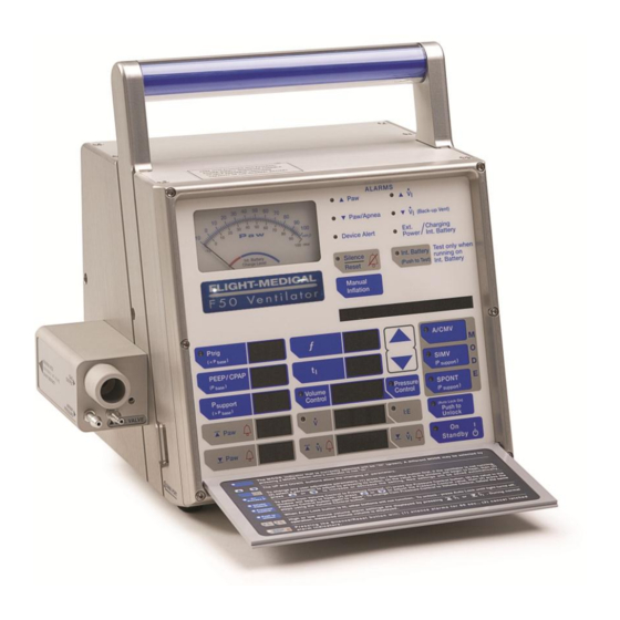
Figure 1 – FLIGHT 50 Ventilator Front Panel 3.2 Front Panel Controls and Indicators Front panel controls that have corresponding LED indicators are included with the description of the control. The FLIGHT 50 Ventilator front panel is shown in Figure 1. Operator's Manual | 3-3... -
Page 26: On / Standby
FLIGHT 50 Ventilator should start ventilation. On: Pressing the On/Standby button once more changes the ventilator from Setting to On. In the On condition, the FLIGHT 50 Ventilator is ventilating and the On/Standby indicator is lit green. Pressing the On/Standby button twice while in On condition turns the ventilator from On to Standby. -
Page 27: A/Cmv Mode (Assist / Control Mandatory Ventilation)
In A/CMV and SIMV, mandatory breaths can be pressure controlled or volume controlled. A green LED indicates which mode is active. If the FLIGHT 50 Ventilator is in Setting condition, changes are made by pressing the requested MODE button once. -
Page 28: Simv Mode (Synchronized Intermittent Mandatory Ventilation)
If patient effort doesn’t cause airway pressure to drop enough to meet the Ptrig threshold or if the patient doesn’t breathe, the FLIGHT 50 Ventilator will deliver the set ƒ (frequency) of mandatory breaths each minute. -
Page 29: Frequency Of Breaths (F)
See page 3- 37 for more information on the Front Panel Message Display Window. When the FLIGHT 50 Ventilator is ventilating and there are no alarm messages displayed on the Message Display Window, press the ▲Up control to access the monitoring information. -
Page 30: I (Inspiratory Time)
determines the total number of mandatory breaths. The frequency or rate value is displayed in the window adjacent to the selector button. The user is alerted to frequency settings which result in an inverse I:E Ratio by an audible beep and an “Inverse I:E” message in the Message Display Window. -
Page 31: Pressure Control (Target Pressure)
3.2.8.1 Switching from Pressure Control to Volume Control: Press the Volume Control button. The set tidal volume is displayed in the adjacent window if the FLIGHT 50 Ventilator is ventilating. A “PRESS AGAIN” message appears in the Message Display Window. -
Page 32: Ptrig (Sensitivity)
2. Adjust the set target airway pressure by pressing the ▲Up/▼Down controls while the LED and numerical display are blinking. 3. If the FLIGHT 50 Ventilator is ventilating, you will need to press the Pressure Control button again within 5 seconds following adjustment. -
Page 33: Psupport
The PEEP/CPAP setting establishes airway pressure in the patient circuit during the exhalation phase. It is also referred to as base or baseline pressure. The set PEEP/CPAP value is displayed in the adjacent window. In Pressure Control ventilation, PEEP/CPAP cannot be set higher than 5 cmH O/mbar below the set Pressure Control setting. -
Page 34: Humidifier On Button
The ▲Paw (High Pressure) alarm is violated Three seconds have elapsed. Manual Inflation is only available in A/CMV and SIMV modes. Manual Inflation may be prematurely cycled off in the first several breaths in Pressure Control when the initial flow has not yet been optimized. -
Page 35: Mandatory Flow)
, etc. The humidifier is operational only when the FLIGHT 50 Ventilator is powered by external A.C. power. If the humidifier and/or the temperature probe is removed... -
Page 36: Internal Battery Test Button And Indicator
3.2.17 Internal Battery Test Button and Indicator Figure 18 – Internal battery Test Button When the FLIGHT 50 Ventilator is powered by the dual internal battery, the LED on this button illuminates as follows: A yellow LED indicates the internal battery system is in use. -
Page 37: Push To Unlock Button And Auto Lock Indicator
3.2.19 Push to Unlock Button and Auto Lock Indicator Figure 20 – Push to Unlock Button and Auto Lock Indicator Auto Panel Lock can be enabled or disabled via User Set Up (see page 3-32). When Auto Lock is set to “Enabled” in User Set Up and the ventilator is in On condition and thirty (30) seconds have elapsed without pressing any buttons, the Auto Lock function is automatically activated and the (Auto Lock On) LED illuminates green. -
Page 38: Paw Meter (Airway Pressure Meter)
The Battery Empty Alarm and the Device Alert Alarm cannot be silenced permanently. These alarms indicate that an alternate source of ventilation must be utilized. See pages 3-23 and 3-25 for more details. 3.2.21 Paw Meter (airway pressure meter) Figure 22 – Paw Meter Range: –10 to 100 cmH O / 98 mbar The Paw meter displays airway pressure. -
Page 39: Paw (High Pressure) Alarm (User Adjustable)
The value in the adjacent display window blinks. 2. Use the ▲Up/▼Down controls to adjust the displayed alarm setting value. 3. The new setting can be retained by: Pressing the selected button again to accept the alarm setting Selecting another parameter for adjustment ... -
Page 40: High And Low Alarm Control And Display (Inspiratory Minute Volume)
The Low ▼Paw Alarm is activated when airway pressure remains below the ▼Paw alarm limit setting for two consecutive mandatory breaths. The alarm violation is cancelled when one mandatory breath is delivered without a ▼Paw alarm violation. The Low ▼Paw Alarm does not function in SPONT mode. The ▼Paw alarm limit does not apply to spontaneous breaths in SIMV mode. -
Page 41: (Low Insp. Minute Volume) Alarm Back-Up Ventilation (User Adjustable)
Figure 27 – ▲ (High Insp. Minute Volume) Alarm Audible Alarm: Intermittent beep indicator blinks red Visual Alarm: ▲ Message Window: HIGH The High Insp. Minute Volume Alarm is activated when the delivered inspiratory minute volume exceeds the High alarm setting. The alarm is cancelled after delivered inspiratory minute volume falls below the ▲... -
Page 42: High Baseline Pressure Alarm (Automatic)
+ 15 cmH O/mbar at 3 seconds after the beginning of expiration, or at the end of expiration, whichever comes first. When the Occlusion alarm is caused by a malfunction inside the ventilator, the FLIGHT 50 Ventilator will Operator's Manual | 3-20... -
Page 43: Low Baseline Pressure Alarm (Automatic)
It is possible that the condition causing the alarm will self-correct, in which case the alarm is reset. Otherwise, the ventilator will continue to alarm until the necessary service is performed. If the FLIGHT 50 Ventilator is unsuccessful in relieving circuit pressure, additional breaths will not be delivered unless airway pressure falls to within 15 cmH O/mbar of baseline. -
Page 44: Apnea Alarm (Automatic)
Visual Alarm: Humidifier indicator blinks yellow The Humidifier Alarm is activated when any of the following conditions occur in the FLIGHT 50 Ventilator built-in humidifier. When an alarm condition is detected the humidifier heater shuts down. There are five humidifier alarms:... -
Page 45: Battery Low Alarm
Excessive temperature in the humidifier heating element. The Humidifier Alarm is automatically set when using the FLIGHT 50 Ventilator humidifier. Humidifier Alarms (and the built-in humidifier) do not function when the FLIGHT 50 Ventilator is powered on internal battery. 3.3.15 Battery Low Alarm Figure 36 –... -
Page 46: Fault, Battery System Alarm, Device Alert (Automatic)
7 to 8 hours to fully recharge. If the FLIGHT 50 Ventilator is to be powered from the dual internal battery for an extended period, ensure that the dual internal battery is fully charged prior to use. -
Page 47: Power Switchover Alarm (Automatic)
If internal battery operation has lasted longer than 60 seconds, there will be a delay of up to an additional 60 seconds before the FLIGHT 50 Ventilator will switch back to external power. If “No ext power” message is still displayed following the re-connection to external power, press Silence/Reset button to cancel the message. -
Page 48: Shut Down Alert Alarm (Automatic)
If the cause of the SYSTEM ERROR does not allow the FLIGHT 50 Ventilator to display the alarm message and the Device Alert indicator to light, the ventilator will shut down and the Shut Down Alert Alarm will activate. -
Page 49: Front Panel Message Display Window
3.4 Front Panel Message Display Window Figure 40 – Front Panel Message Display Window All messages and alarms are displayed in a 16 character, alpha numeric window located above the MODE controls. 3.4.1 Message Monitoring When the Message Display Window is blank, with no messages displayed, press the ▲Up control to scroll through the available monitoring messages. -
Page 50: Alarm And Caution Messages
i – Insp. Minute Volume (in L/min) rounded to nearest whole number ƒ – Total number of patient or time activated breaths detected for the last 60 seconds (in b/min) Line 2: “Paw Pxx Mxx Bxx” P – Peak airway pressure of last breath M –... -
Page 51: Left Side Connectors
Panel Locked: Notifies user that the front panel buttons are now locked PRESS AGAIN: Notifies user that a second press on the same button is required in order to confirm change requested. 3.5 Left Side Connectors The round heater for the optional humidifier is located near the left side connectors. -
Page 52: Right Side Connectors
12-30 VDC, max. 12A 50/60/400 Hz The FLIGHT 50 Ventilator uses a single inlet for both A.C. and D.C. power sources. The inlet power connector automatically recognizes A.C. voltage ranges from 100 to 240 and D.C. ranges from 12 to 30. A FLIGHT MEDICAL approved external battery can be attached to this connector. -
Page 53: Equipotential Connector
21% to 100% FIO2. The high pressure oxygen hose has a standard female DISS 1240 connection. The Mixer attaches to the Fresh Gas Intake of the FLIGHT 50 Ventilator on the Filter Cover, located on the right side of the ventilator. -
Page 54: Oxygen Blending Bag Kit
User Set Up and makes changes. To enter User Set Up the FLIGHT 50 Ventilator must be in the Standby condition. To access User Set Up, when connected to A.C. power: 1. -
Page 55: User Set Up Parameter
Int. Battery button. Use the ▲Up/▼Down control buttons to change the parameter setting. To exit User Set Up, press the Silence/Reset button once. The FLIGHT 50 Ventilator is now ready for use. Table 3 1 – User Set Up Parameters ▲... - Page 56 Default parameters are listed on page 2-1. HOME CAREGIVERS: This parameter should always be set to USER for home use to ensure that when the FLIGHT 50 Ventilator is powered off and on the physician directed ventilation settings remain in place.
-
Page 57: Theory Of Operation
The dual micro pistons’ ability to deliver a variable flow enables the FLIGHT 50 Ventilator to provide a full range of operating modes and breath types, including Assist Control, SIMV... -
Page 58: Setting The Main Parameters
The FLIGHT 50 Ventilator is available with a built-in humidifier or without. The FLIGHT 50 Ventilator is very easy to set up and use with clear indications of all ventilation and alarm settings and alarm violations. When the FLIGHT 50 Ventilator is used in a home care... -
Page 59: Spont Mode (Spontaneous Ventilation)
When PEEP/CPAP is set above 0, the ventilator mode is CPAP (without Psupport) or Bi-level Positive Airway Pressure (with Psupport). Ensure that Ptrig is set so the FLIGHT 50 Ventilator detects all spontaneous patient efforts. Entries for tidal volume, pressure control, ƒ, t and Low Paw alarm limit are all inactive in SPONT mode. -
Page 60: Psupport (Pressure Support)
As with all FLIGHT 50 Ventilator operating modes, Back-up Ventilation is activated if the Low alarm limit is violated. 4.6 Psupport (Pressure Support) Psupport only functions during patient activated spontaneous breaths in SIMV and SPONT modes. During each spontaneous breath, the ventilator supports the patient by elevating the airway pressure to the Psupport + PEEP level. -
Page 61: Back-Up Ventilation
During Back-up Ventilation, the Silence/Reset button can be tapped to silence the audible alarm. This will not cancel Back-up Ventilation. Back-up Ventilation in the FLIGHT 50 Ventilator is based on the delivered inspiratory minute volume. The inspiratory minute volume may be different from the expiratory minute volume in some conditions, such as in the case of a patient breathing circuit or patient airway leak. -
Page 62: Cancellation Of Back-Up Ventilation
If delivered inspiratory minute volume exceeds the Low alarm setting by 10%, Back-up Ventilation is cancelled, the audible alarm stops, the Low (Back-up Vent) alarm indicator latches and the FLIGHT 50 Ventilator ▼ resumes ventilation at the user-selected parameters. Press the Silence/Reset button to cancel the latched alarm indicator and alarm message in the Message Display Window. -
Page 63: Ventilator Setup And Use
5.1 Introduction Familiarize yourself with the instructions in this section prior to ventilating patients with the HT FLIGHT 50 Ventilator. Following all of the listed steps is essential to ensuring the safest possible operation of the ventilator. Use the information in this section in conjunction with established hospital protocols and homecare dealer instructions. -
Page 64: Ventilator Set Up Procedure
3. Remove the white plastic cord restraint next to the power entry module. 4. Slip the power cord into the restraint. 5. Plug the power cord into the power entry module and re-attach the restraint with cord onto the side of the FLIGHT 50 Ventilator. Operator's Manual | 5-2... - Page 65 Be careful to position the cord so that it won’t interfere with the Air/Oxygen Entrainment Mixer attachment. Figure 48 – Power Cord Ferrite 6. Verify that the A.C. power cord supplied with the FLIGHT 50 Ventilator has the Power Cord Ferrite attached between the adapter box and the ventilator.
-
Page 66: Exhalation Valve Calibration
3. Press the On/Standby button once to enter Settings condition. 4. Press the Manual Inflation button once, then again within three seconds. 5. The FLIGHT 50 Ventilator will start the EZ Cal and the ventilator will automatically test the exhalation valve. If it passes the test, the messages "Cal Completed", then "Press ON to Vent"... - Page 67 Some disposable breathing circuit/exhalation valve assemblies are not compatible with the FLIGHT 50 Ventilator due to the requirements of the ventilator’s sophisticated servo-controlled, pressure management system. If your disposable circuit fails consistently, switch to a FLIGHT MEDICAL approved, reusable FLIGHT 50...
-
Page 69: Patient Set Up Procedure
4. Following the self-test, the FLIGHT 50 Ventilator enters Settings condition in which the ventilation parameters may be adjusted but the FLIGHT 50 Ventilator does not ventilate. The On indicator does not illuminate when the FLIGHT 50 Ventilator is in the Settings condition. - Page 70 12. Check all alarm limit and control settings to ensure they are appropriate for the patient to be ventilated. 13. If the FLIGHT 50 humidifier is being used, set the target temperature level. 14. Press the On/Standby button again to initiate ventilation. The On indicator illuminates.
-
Page 71: Built -I N Humidifier
20. To power down the FLIGHT 50 Ventilator after it is removed from the patient, press the On/Standby button twice. An audible beep sounds and the FLIGHT 50 Ventilator automatically shuts down. Press the Silence/Reset button to mute the audible alarm. -
Page 72: General Description
The FLIGHT 50 humidifier is powered on independently from the ventilator. But when the ventilator is switched from On to Standby, the humidifier is also turned off. -
Page 73: Set Up And Operation
8. Connect the short side of the Humidifier Temperature Probe cable to the port on the top of the humidifier bottle. 9. Plug the electrical connector into the side of the FLIGHT 50 Ventilator and then connect the other end of the cable to the temperature probe port on the exhalation valve. -
Page 74: Oxygen Accessories
6-12. 5.6 Oxygen Accessories Continuous oxygen monitoring is required for patient safety. The FLIGHT 50 Ventilator does not have a built-in alarm system to notify user of a failure or disconnection of the oxygen source. Ensure that the oxygen source is not empty before and during the use of Air/Oxygen Entrainment Mixer or Oxygen Blending Bag Kit. - Page 75 An optional Air/Oxygen Entrainment Mixer (p/n V13-00010-60) is designed for exclusive use with the FLIGHT 50 Ventilator. It is used to blend atmospheric air with pressurized medical grade oxygen at a precise ratio. The standard oxygen inlet connection is DISS 1240.
-
Page 76: Oxygen Blending Bag Kit (Optional Accessory)
5.6.2 Oxygen Blending Bag Kit (Optional Accessory) The Oxygen Blending Bag Kit is designed for use with the FLIGHT 50 Ventilator. The Oxygen Blending Bag Kit (p/n V17-00001-67) allows the operator to ventilate patients with oxygen enriched gas of up to 100% oxygen. - Page 77 5.6.2.1 Installing the Oxygen Blending Bag Kit The Oxygen Blending Bag Kit attaches into the Fresh Gas Intake port on the Filter Cover, located on the right side of the FLIGHT 50 Ventilator. The following materials are required for Installation: ...
- Page 78 7. Adjust the oxygen flow meter to the appropriate liter-flow to obtain the desired level of oxygen enrichment. 8. Monitor regularly the patient's inspiratory minute volume and delivered , and adjust the oxygen liter flow as necessary to maintain the prescribed level of oxygen enrichment.
- Page 79 Figure 52 – Oxygen Supply Flow for Desired % of Oxygen Enrichment without PEEP When PEEP is added, it changes the mixing of oxygen with air. Use the chart in Figure 52when the patient is ventilated without PEEP; use the chart in Figure 53 in the presence of PEEP. Data in the chart in Figure 53 are taken at an I:E ratio of 1:2.
-
Page 80: Cleaning And Maintenance
6 Cleaning and Maintenance 6.1 Cleaning and Disinfecting The FLIGHT 50 Ventilator and associated patient circuits are shipped in clean but not sterile condition. Reusable (single patient) patient circuits should be disinfected before reapplying to the patient. Use the information in this section in conjunction with hospital policy, physician prescription, or Homecare Dealer instructions. -
Page 81: Flight 50 Ventilator
6.1.1 FLIGHT 50 Ventilator Wipe clean the FLIGHT 50 Ventilator between patients, and once a week while in use. To clean the ventilator: 1. Wipe clean the exterior (besides the screen) of the ventilator and all parts not in direct contact with patients, using a cloth that has been dampened with a medical detergent or alcohol-based cleaning solution. - Page 82 Figure 54 – Humidifier Assembly To disassemble the Humidifier: 1. Remove the humidifier bottle from the FLIGHT 50 Ventilator. 2. Open the humidifier bottle and remove the heat sink. 3. Remove the absorbent paper from the heat sink and discard.
-
Page 83: Humidifier Temperature Probe
To sterilize the Humidifier: The following sterilizing methods are suitable for the bottle and heat sink. 1. Soak in an approved chemical sterilant following the manufacturer’s instructions. 2. Rinse thoroughly with sterile, distilled water. 3. Air dry. Autoclave 121ºC / 250ºF for 20 min. FLIGHT MEDICAL recommends that only sterile, distilled water be used in the humidifier to prevent build-up of mineral deposits. -
Page 84: Reusable Patient Circuits
Shake off excess water and place all parts on a clean towel to air dry. (Do not heat or blow dry.) To disinfect the Humidifier Temperature Probe: 1. Soak the probe tips in one part white vinegar to one part of water for 2 hours. - Page 85 HOME CAREGIVERS: In the home environment, it is important to always use a clean, disinfected patient circuit. The objective of cleaning circuits is to render the surfaces free of pathogens. If you are using a FLIGHT MEDICAL reusable breathing circuit refer to cleaning directions below.
- Page 86 Patient circuit components should NOT come in contact with the following solutions, because they may cause disintegration of the tubing: Hypochlorite, Phenol (>5%), Inorganic Acids, Formaldehyde, Ketone, Chlorinated Hydrocarbons, and Aromatic Hydrocarbons. Patient circuits should be inspected after disinfecting to check for deterioration.
- Page 87 This may cause the diaphragm to become wrinkled or unseated and affect ventilator performance. 6.1.5.2 FLIGHT 50 Ventilator Air Inlet Particle Filter NEVER operate the FLIGHT 50 Ventilator without a clean inlet particle filter in place. NEVER reverse the inlet particle filter when it is dirty.
- Page 88 Since there is no purge flow coming from the FLIGHT 50 Ventilator, it is important to always use a Proximal Inline Filter. Check the Prox Inline Filter weekly. Discard it and replace with a new filter if it appears to have gotten wet or come in contact with a contaminant.
-
Page 89: Maintenance
Do not wash or sterilize the Prox Inline Filter. 6.2 Maintenance 6.2.1 Preventive Maintenance It is recommended to take the following measures to maintain the FLIGHT 50 Ventilator: Check the Air Inlet Filter (located behind the Filter Cover) weekly. -
Page 90: Hour Maintenance
To preserve Dual internal battery life: Whenever possible, plug the FLIGHT 50 Ventilator into the external power source to charge the batteries. Check that the green “Ext. Power” LED is lit. Always keep Power Save function ON. Always have available a backup power source, AC Power Cord and optional Autolighter Power Cord Accessory (p/n A01-00040-29). - Page 91 Certain components of the ventilator, such as the exhalation valve and the front panel, consist of materials that are sensitive to some organic solvents used for cleaning and disinfection (such as phenols, halogen releasing compounds, oxygen releasing compounds, and strong organic acids).
-
Page 93: Ventilator Quick Check Procedure
HOME CAREGIVERS: This procedure should be performed by your Homecare equipment provider, prior to delivery of the FLIGHT 50 Ventilator, to verify proper operation. It can also be performed in the homecare environment to ensure proper setup and function of the ventilator. -
Page 94: Quick Check Procedure
3. Connect a patient circuit with 500 ml test lung, to the FLIGHT 60 Ventilator. 4. Calibrate the exhalation valve See Section 7 .4.2. 5. Press the On/Off button once. The ventilator performs a brief self-test and enters SETTINGS mode. During the self-test, verify that the ventilator purges, an audible alarm sounds and that all indicator LEDS illuminate. -
Page 95: Alarms And Indicators Check
7.2.2 Alarms and Indicators Check 1. If the FLIGHT 50 with a humidifier is being used, press Humidifier On button and use ▲/▼ control button to set the desired temperature. 2. Press the On/Standby button again to exit Settings condition and start ventilation. -
Page 96: Paw Monitor / Pressure Meter Check
= 6-9 and ƒ = 13-17 is displayed. 7.2.5 Internal Battery Check To check the Internal Battery: 1. Unplug the FLIGHT 50 from AC power 2. Clear the alarm with the Alarm/Silence button 3. Press and hold the Int. Battery (Push to Test) button while powered on internal battery. -
Page 97: Check-Off Sheet
7.3 Check-Off Sheet HOME CAREGIVERS: Initial set up and verification of the ventilator operation should be done by the caregiver in conjunction with the Homecare Dealer or hospital provided clinician. The Abbreviated Check Procedure may be performed in the homecare environment to ensure proper set up and function of the ventilator. -
Page 98: Abbreviated Check Procedure
3. Press the On/Standby button once to enter Settings condition. 4. Press the Manual Inflation button once, then again within three seconds. 5. The FLIGHT 50 will start the EZ Cal and the ventilator will automatically test the exhalation valve. If it passes the test, the messages "Cal Completed", then "Press ON to Vent"... -
Page 99: Battery Function And Charge Level Verification
A.C. power. An audible alarm should be heard (Power Switchover Alarm). Press the Silence/Reset button to cancel alarm. 2. While the FLIGHT 50 is operating on the dual internal battery, push and hold the Int. Battery Test button. Observe the needle indicator on the Paw meter. -
Page 101: Index
Index 8 Index 10V SHUTDOWN 3-25 Ptrig 3-10 A/CMV mode Push to Unlock 3-15 A/CMV Mode Silence/Reset 3-15 Accessories 5-11 Buttons Adjusting parameters A/CMV Mode Air / Oxygen Entrainment Mixer 5-11 Frequency of Breaths Air Inlet Particle Filter Inspiratory Time Air/Oxygen Entrainment Mixer 1-2, 1-3, 3-31 On/Standby... - Page 102 Exhalation Valve 3-29 mechanical ventilation Exhalation Valve Calibration Message Window 3-17 External Power Connector 3-30 Mode FAULT BAT SYS 3-24, 3-25 A/CMV Filter Cover 3-30 SIMV Frequency 3-27 SPONT Frequency of Breaths Mode Control Fresh Gas Intake 3-30 Monitored Information Front Panel 3-1, 3-27 Monitoring...
- Page 103 Index Preventive Maintenance 6-11 Silence/Reset button 3-15 Proximal Inline Filter 6-10 SIMV Psupport SIMV Mode PSupport Button 3-11 SPONT mode Ptrig Button 3-10 SPONT Mode Push to unlock button Standby button Push to Unlock Button 3-15 Storage Humidity Reached Max I:E 3-28 Storage Temperature Reusable Exhalation Valve...
Need help?
Do you have a question about the FLIGHT 50 and is the answer not in the manual?
Questions and answers