Table of Contents
Advertisement
Advertisement
Table of Contents

Subscribe to Our Youtube Channel
Related Manuals for Canyon CNP-WF514


Summary of Contents for Canyon CNP-WF514
- Page 1 CNP-WF514 Wireless Broadband Router User Manual...
-
Page 2: Table Of Contents
Table of Contents INTRODUCTION ..........................4 AFETY RECAUTIONS ........................4 ACKAGE ONTENTS ........................5 ARDWARE VERVIEW ........................6 GETTING STARTED ........................7 ONNECTING TO EVICE .......................7 XP S INDOWS ETUP ........................7 INDOWS ISTA ETUP .......................8 2000 S INDOWS ETUP .......................8 98/ME S INDOWS ETUP ......................8 DEVICE CONFIGURATION .......................10 NTERNET ONNECTION... - Page 3 MAC Filtering Configuration..................33 Connection Filtering Configuration................34 URL Filtering Configuration..................35 Ping Filtering Configuration..................35 SPI F IREWALL ..........................35 DDNS ..............................36 MISC ...............................37 Login ID & Password Setup ..................37 Remote Management .......................37 UPnP Setup ..........................38 System Time Setup ......................38 WAN Link Status & Setup ....................38 Restore Default/Restart System................39 Firmware Upgrade......................39 TROUBLESHOOTING........................40...
-
Page 4: Introduction
Thank you for purchasing CANYON CNP-WF514. We sincerely wish you to enjoy the wireless broadband router. It provides user an easy and stable high speed internet connection. It is also equipped with built-in NAT technology that acts as a firewall to protect the network from outside intrusions. Ultimately, the device is implemented with an IEEE 802.11b/g access point which is capable of wireless LAN... -
Page 5: Package Contents
Package Contents Product Image Item Name CNP-WF514 Main Unit Standing Base Power Adapter Warranty Card Quick Guide Documentation CD... -
Page 6: Hardware Overview
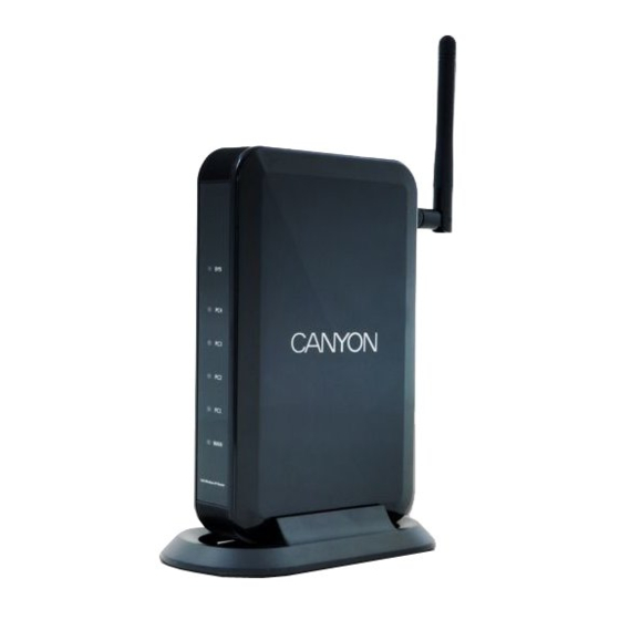
Hardware Overview PC1/PC2/ PC3/PC4 Power status indicator WAN interface status indicator PC1/PC2/PC3/PC4 LAN interface status indicator Antenna PC1/PC2/ DC Jack PC3/PC4 Default DC Jack Connects to power adapter Connects to cable/DSL modem or other Ethernet devices PC1/PC2/PC3/PC4 Connects to LAN port on PC or other Ethernet devices Default Reset device to factory default settings Antenna... -
Page 7: Getting Started
Getting Started Connecting to Device Please follow the steps below to connect the modem and PC(s) with CANYON CNP-WF514: 1. Begin by searching for an appropriate location to setup device. Please keep in mind to keep the device in the center of working area as the signal strength and data transfer rate falls off with distance. -
Page 8: Windows Vista Setup
Windows Vista Setup Click on Start Settings Network Connections. Right click on Local Area Connection icon and click on Properties. Click on Continue in User Account Control dialog box. Select TCP/IPv4 option and click on Properties. The Properties dialog box will be displayed. - Page 9 by selecting them and clicking on Remove. From DNS Configuration dialog box, remove all entries from DNS server search order box and Domain suffix search order box by selecting them and clicking on Remove. Click on Disable DNS. Click Ok to confirm modifications. NOTE: To access the device via a wireless connection, PC must be equipped with 802.11b or 802.11g wireless adapter/PCI card.
-
Page 10: Device Configuration
Before setting up the device, please make sure that the host PC(s) is set on the IP sub-network accessible by CANYON CNP-WF514 device. The default network address of the device is set as 192.168.1.1. Please configure IP address of host PC at 192.168.1.XXX where XXX is a number between 002 and 254. -
Page 11: Internet Connection Wizard
Internet Connection Wizard Start Internet Configuration Wizard Internet Configuration Wizard will pop up upon successful login. NOTE: In order to enter Wizard mode, temporarily disable popup window blocking option if necessary or click on Wizard to start. Select pop up to enable automatic Internet Configuration Wizard prompt window. - Page 12 Select 1 of 7 connection types instructed by ISP or network administrator. Click on Next to continue or Prev to go back to previous page. Click on Exit to exit. DHCP Connection Click on Clone MAC or type in MAC address if required by ISP. Click on Default MAC to restore to default MAC address.
- Page 13 Type in PPPoE Account and PPPoE Password provided from ISP. Click on Next to continue or Prev to go back to previous page. Click on Exit to exit. Static IP Connection Type in IP Address, Subnet Mask, Gateway, Primary DNS, and Secondary DNS provided from ISP.
- Page 14 Type in PPTP User Name, PPTP Password, Server IP Address, Primary DNS, and Secondary DNS provided from ISP. Click on Next to continue or Prev to go back to previous page. Click on Exit to exit. PPTP Static IP Connection Type in PPTP User Name, PPTP Password, Server IP Address, Subnet Mask, Gateway, Primary DNS, and Secondary DNS provided from ISP.
- Page 15 Type in L2TP User Name, L2TP Password, Server IP Address, Primary DNS, and Secondary DNS provided from ISP. Click on Next to continue or Prev to go back to previous page. Click on Exit to exit. L2TP Static IP Connection Type in L2TP User Name, L2TP Password, Server IP Address, Subnet Mask, Gateway, Primary DNS, and Secondary DNS provided from ISP.
- Page 16 Select a Radio Band type from the drop down box. (802.11b/g is recommended) Select Radio Mode from the drop down box. (AP+WDS is recommended) Type in SSID as desired. (SSID must be identical in all devices connecting to device) Select a broadcasting channel from drop down box. (Device is set on channel 6 by default) Click on Next to continue or Prev to go back to previous page.
-
Page 17: Status
Status This section displays various router information divided into 3 tabs. The 1 tab displays parameters of WAN/LAN/Wireless connection, and System Info. WAN Status: WAN interface parameters of the device. NOTE: Click on Connect to refresh IP address with DHCP connection type and to initiate a dial up connection with PPPoE connection type. - Page 18 The 2 tab displays statistics of packets from WAN port. Click on Refresh to update data monitor table to receive most recent data. System Run Time: Displays system run time from last system restart. Statistics: Monitors current sent/received packets through both wireless and wired connection.
-
Page 19: Wan Setup
WAN Setup This section assists user to setup network connection types and their subsidiary functions. The default setting is Dynamic IP connection type. Click on Save to save modified settings. Dynamic IP Setting Click on Dynamic IP User (Cable Modem) option. Click on Clone MAC to replace current device MAC address with host PC MAC address. -
Page 20: Pppoe Setting
NOTE: It is recommended to set MTU value between 1200 and 1500 range. Enter Primary DNS and Secondary DNS IP address if required by ISP provider. Click on Apply to confirm modifications. Click on Save to save modified settings. PPPoE Setting Click on PPPoE User (ADSL) option. -
Page 21: Static Ip Setting
Static IP Setting Type in WAN IP Address, Subnet Mask, Default Gateway, Primary DNS and Secondary DNS address provided by ISP. Click on MAC Clone to replace current device MAC address with host PC MAC address. Click on Default MAC to restore to default. Enter MTU (Maximum Transmission Unit) value if required. -
Page 22: L2Tp Setting
Type in User Name and Password provided by ISP. Type in PPTP Server IP Address. Select connection type. Please follow instructions from ISP. Enter Static WAN IP Address/Subnet Mask/Gateway if necessary. Enter Primary DNS and Secondary DNS IP address if required by ISP provider. Enter MTU (Maximum Transmission Unit) value if required. -
Page 23: Lan Setup
Type in User Name and Password provided by ISP. Type in PPTP Server IP Address. Select connection type. Please follow instructions from ISP. Enter Static WAN IP Address/Subnet Mask/Gateway if necessary. Enter Primary DNS and Secondary DNS IP address if required by ISP provider. Enter MTU (Maximum Transmission Unit) value if required. - Page 24 The 1 tab configures PC(s) connected to device and other settings. Type in System IP Address of device LAN port IP address. This is the default gateway IP address of LAN client(s)/host PC(s). Type in Subnet Mask of the device LAN segment. Enable/disable DHCP Server function by clicking on the option.
-
Page 25: Wireless
Wireless Basic Setting This section assists user to create a network environment that connects wireless PC(s) to a wired LAN. It also allows wireless stations to access network resources and share the broadband Internet connection. The section is divided into 6 tabs. The 1 tab defines basic settings for wireless networking. -
Page 26: Security Setting
Security Setting The 2 tab defines all common security settings for wireless networking. Select one of the Authentication Type from the drop down menu box. None: Any data will be transmitted without encryption and any PC(s) is able to connect to device without authentication. This is the default setting. Click on Apply to confirm modification. - Page 27 WPA Personal: WPA (Wi-Fi Protected Access) is an advanced security standard that utilizes pre-shared key to authenticate wireless stations and encrypt data during communications. Select Authentication & Encryption type (TKIP and AES) from the drop down menu box. Type in Pass Phrase with size ranging from 8 to 63 characters under KEY option.
-
Page 28: Filter List Setting
Type in Pass Phrase with size ranging from 8 to 63 characters under KEY option. Specify time WPA key must be renewed. The default value is 86400. Click on Apply to confirm modification. WPA&WPA2 Personal: Auto-select WPA or WPA2 detects PC wireless authentication information and adjusts its setting accordingly. -
Page 29: Wds Setting
Type in MAC address of PC(s) and optional comments if necessary under Descript box. Click on Add to edit modified rule. An Access Control Table below displays all PC(s) under access control on the network. Select a rule and click on Delete to remove it from table. Click on Save to save modified settings. -
Page 30: Association Table
Type in DTIM Interval frequency between each DTIM (Delivery Traffic Indication Message) broadcast. Lower value result in more efficient networking while preventing PC(s) from entering power saving mode. Higher value interferes with wireless transmission yet allowing PC(s) to enter sleep mode thus saving power consumption. -
Page 31: Nat
Network Address Translation (NAT) technology allows multiple users at local network to gain access to Internet through a single public IP address while user PC(s) are still under firewall protection. DMZ Host Setup DMZ function enables PC to be exposed to the Internet for use of special purpose services. -
Page 32: Port Triggering
Virtual server allows PC(s) located outside of network to be able to access services on PC(s) connected to the device. Type in the description of the rule desired under Rule Name. Type in internal IP address of the client PC(s) desired for public port number packet access. -
Page 33: Firewall
Select inbound port protocol type between TCP and UDP under Forward Protocol. Type in all of the inbound range of port numbers. Port numbers are separated by comma. Click on Add to add modified rule. A Trigger Port Table below displays all valid trigger rules available on the network. Select a rule and click on Delete to remove it from table. -
Page 34: Connection Filtering Configuration
Connection Filtering Configuration Connection Filtering function blocks certain PC(s) from Internet access based on time. Click on Start/Stop to turn on/off the MAC filtering configuration. Check the option to allow all other PC(s) whose IP address(es) are not on the list to be permitted of Internet access. -
Page 35: Url Filtering Configuration
URL Filtering Configuration URL Filtering function blocks certain website accesses by specifying keywords. Type in keywords to block PC(s) from accessing Internet websites. Wildcards such as “*” (a string of characters) or “?” (a single character) are available. Click Add to add modified rule. -
Page 36: Ddns
Check on Set SPI Firewall State and click Apply to activate SPI Firewall function. Check on Limit the max session of the host and specify its maximum session value to limit network sessions. Click on Apply to confirm modifications. Check on Limit the max unfinish session of the host and specify its maximum unfinished session value to limit unfinished network sessions. -
Page 37: Misc
Click on Start/Stop to turn on/off DynDNS Operation. NOTE: User must sign up on www.dyndns.org to obtain DynDNS service before starting. Type in account name, password, and domain obtained from DDNS provider. Click Apply to confirm modification and Refresh to display most recent update. Click on Save to save modified settings. -
Page 38: Upnp Setup
The Remote Management function allows user to manage the device through Internet from a remote location. Check Management Port option and type in the corresponding port number. Click Apply to confirm modifications. Click on Save to save modified settings. NOTE: To access web based management page, simply type in http://<WAN IP Address>:8080 (for example: http://192.168.1.8:8080). -
Page 39: Restore Default/Restart System
Restore Default/Restart System Click on Restore Default to restore all device settings to factory setting. Click on Restart System to reboot the device. Firmware Upgrade Click on Browse to locate firmware file on host PC. Click Apply to confirm modifications. NOTE: Press briefly on Default button to reset the device. -
Page 40: Troubleshooting
Troubleshooting Please refer to the following procedures if CNP-WF514 does not function as it should be. Be advised that the following instructions are only intended for simply troubleshooting purpose. Please contact your local authorized shops for further troubleshooting and technical support. -
Page 41: Appendix
Appendix Technical Specifications Standards IEEE 802.3, IEEE 802.3u, IEEE 802.11g, IEEE802.11b Channels 13 Channels Management Interface Web Based Network Ports WAN: 1 X 10/100 RJ-45 Port LAN: 4 X 10/100 RJ-45 Ports (with switching function) Cabling Type Cat 5 Ethernet Network Cable 15 ±...
Need help?
Do you have a question about the CNP-WF514 and is the answer not in the manual?
Questions and answers