JVC KY-F560 Instruction Manual
Colour video camera
Hide thumbs
Also See for KY-F560:
- Instruction manual (48 pages) ,
- Sales manual (49 pages) ,
- Specification (4 pages)
Table of Contents
Advertisement
Quick Links
COLOUR VIDEO CAMERA
FARBVIDEOKAMERA
APPAREIL VIDEO EN COULEURS
KY-F560
Thank you for purchasing this JVC product.
Before operating this unit, please read the
instructions carefully to ensure the best
possible performance.
*Illustration with optional lens attachment.
*Illustration mit montiertem optionalem Objektiv.
*Illustration avec objectif optionnel.
INSTRUCTION MANUAL
BEDIENUNGSANLEITUNG
MODE D'EMPLOI
LWT0164-001A
Advertisement
Table of Contents

Related Manuals for JVC KY-F560


Summary of Contents for JVC KY-F560
-
Page 1: Instruction Manual
APPAREIL VIDEO EN COULEURS KY-F560 *Illustration with optional lens attachment. *Illustration mit montiertem optionalem Objektiv. *Illustration avec objectif optionnel. Thank you for purchasing this JVC product. Before operating this unit, please read the instructions carefully to ensure the best possible performance. INSTRUCTION MANUAL BEDIENUNGSANLEITUNG MODE D’EMPLOI... - Page 2 This equipment is in conformity with the provisions and protection requirements of the corresponding European Directives. This equipment is designed for professional video ap- pliances and can be used in the following environments: 5 Residential (including both of the location type class 1 and 2 found in IEC 1000-2-5) 5 Commercial and light industrial (including, for example, theatres) 5 Urban outdoors (based on the definition of location type class 6 in IEC 1000-2-5) This apparatus is designed for rack mounting or is used close to other apparatus.
-
Page 3: Safety Precautions
SAFETY PRECAUTIONS WARNING: TO REDUCE THE RISK OF FIRE OR ELECTRIC SHOCK, DO NOT EXPOSE THIS APPLIANCE TO RAIN OR MOISTURE. This unit should be used with 12 V DC only. CAUTION: To prevent electric shocks and fire hazards, do NOT use any other power source. -
Page 4: Table Of Contents
Thank you for purchasing this product. Contents 1. Getting Started Features ... 6 Points to Note During Use ... 7 Part Names and Functions ... 8 Description of Terminals ... 11 2. Preparation Before Shooting Basic System ... 12 Applied System ... 13 Mounting the Lens ... - Page 5 5. Setting Via the Menu Screen Flow of Menu Screens ... 28 Setting Procedures ... 30 “EXPOSURE” Screen ... 31 “ADVANCED EXPOSURE” Screen ... 33 “WHITE BALANCE” Screen ... 34 “PROCESS (1/2)” Screen ... 36 “PROCESS (2/2)” Screen ... 38 “MATRIX ADJUST”...
-
Page 6: Getting Started
1.Getting Started Features ● Supersensitive and high-performance camera that realizes a horizontal resolution of 850 lines and F13/ 2000 lx via three and a half inch CCD and 12-bit DSP processing. Enables camera control and hence offers a wide range of uses via use of cameras for high resolution monitoring, relay, data transmission, weddings and conventions with a swivel base. -
Page 7: Points To Note During Use
Points to Note During Use • For important shootings, perform trials in advance to ensure that they are properly recorded. • We will not compensate for contents lost due to the malfunction of this unit. Characteristic CCD Phenomena • Smear and Blooming When shooting a bright light source, the CCD may induce white streaks (smear) in the vertical direc- tion of the light source. -
Page 8: Part Names And Functions
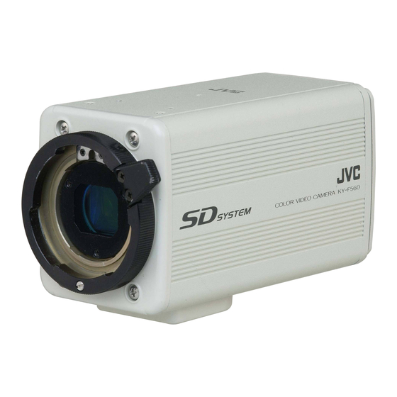
1. Getting Started (continued) Part Names and Functions Front / Bottom Lens Mounting Ring/Lens Lock Lever When dismounting the lens, do so by holding the lens and turning the lens lock lever in the anti-clockwise direction. When mounting the lens, check that the guide pins of the lens are aligned, followed by turning the lens lock lever in the clockwise direction to fasten. - Page 9 Part Names and Functions (continued) Back [MENU] Menu Button Press this button for 1-2 seconds. Menu screen will be output from the [VIDEO OUT] terminal. Press the button for 1-2 seconds again to clear the menu screen. ☞ Page 30 ‘Setting Procedures’ [SET] Set Button When the menu screen is displayed, use it to select a submenu or to confirm a selected item...
- Page 10 Inputs composite video signals or black burst signals. Slot Cover for Option Cards Remove the cover to install the option card. ☞ Page 46 ‘Connecting Optional Devices’ Please consult your JVC-authorized dealer on optional devices. LENS POWER...
-
Page 11: Description Of Terminals
IRIS POSITION IRIS A/R 9~12 Remote Terminal (Mini DIN 6 Pin, Female) Pin No. Notes • Please consult your JVC-authorized dealer on connection of remote terminals. • Ensure to use cables that are shielded. Signal OPERATE (L:ON) SID2(TX) SID1(RX) + 9 V Output... -
Page 12: Preparation Before Shooting
When connecting • Perform this when the unit is off. • Read the instruction manual of the unit before performing it. • Consult your JVC-authorized dealer on details of the equipment in use of cables with the RS-232C PC CAMERA CONTROL... -
Page 13: Applied System
When connecting • Perform this when the unit is off. • Read the instruction manual of the unit before performing it. • Consult your JVC-authorized dealer on details of the equipment in use of cables with the LENS REMOTE CONTROL (FUJINON) -
Page 14: Mounting The Lens
2. Preparation Before Shooting (continued) Mounting the Lens Follow the procedures below when mounting the auto iris lens. Refer to the ‘instruction manual’ for the lens and lens remote control as well. Lens Compatible MD Zoom Lens S16 x 7.3 BMD (Fujinon) YH16 x 7 BKTS (Canon) Loosen by turning the lens lock lever in the anti-clockwise direction. -
Page 15: Connecting The Power Supply
Connecting the Power Supply Connect the [DC IN] terminal at the back of this unit to the [TO CAMERA] terminal of the AC adaptor (AA- P700) using the power cable supplied (2 m). AA-P700 AC Adaptor AC 100V White Marking AC 120 V Connect the end with white marking to the AC... -
Page 16: Mounting The Camera
2. Preparation Before Shooting (continued) Mounting the Camera <Mounting Procedures> Anti-rotation Hole Screw Hole for Mounting Camera Camera Mounting Bracket <Changing the Camera Mounting Bracket> E-16 • To mount this unit, make use of the screw holes for mounting the camera on the camera mounting bracket. -
Page 17: Precautions To Prevent Camera From Falling
Precautions to Prevent Camera From Falling Safety cable to Prevent Falling of Equipment 6 mm Camera Head ● Special attention is required when mounting to the wall or ceiling. Get a contractor to perform the work and avoid doing it on your own. Unit may fall off and cause injuries or accidents. -
Page 18: Setting And Adjustment During Shooting
3. Setting and Adjustment During Shooting External Monitor Adjustment Display the built-in colour bars signal at the camera on the monitor to perform colour/contrast/brightness adjustment. [BARS] button AW BARS MENU REMOTE LENS VIDEO OUT GENLOCK IN DC IN POWER SEE INSTRUCTION MANUAL 3.~7. -
Page 19: Back Focus Adjustment
Back Focus Adjustment When the lens is mounted for the first time, adjust back focus of the lens if the focus for telephoto/wide angle during zoom is not aligned. • Check whether the macro ring has been moved before adjustment. If so, restore the macro fixing knob to the original position. -
Page 20: White Balance Adjustment
3. Setting and Adjustment During Shooting (continued) White Balance Adjustment Colour of light (colour temperature) may vary with light sources. When light source for illumination of object is changed, adjust white balance (AUTO WHITE) again. Do not place strong reflectors such as metals near the object. -
Page 21: Error Display
White Balance Adjustment (continued) O WH ITE 1 G : OB J E CT Object Error O WH ITE 1 ERRO R : LO W L I Insufficient Illumination O WH ITE 1 ERRO R : OV E R L Excessive Illumination Full-time Auto White (FAW) Function Automatic adjustment of white balance according to different illumination conditions. -
Page 22: White Shading Adjustment
3. Setting and Adjustment During Shooting (continued) White Shading Adjustment There are cases when white balance is achieved for the center of the screen but not for the upper and lower ends, hence causing other colours to appear with green or magenta. This is brought about by the lens characteristics. - Page 23 White Shading Adjustment (continued) 5. 6. Blinking WHI TE BA LAN CE - WH I TE BA LAN MANUA L EVE L ( R ) L EVE L ( B ) S H AD I NG MANUA L EVE L ( R ) L EVE L ( G ) L EVE L ( B ) PAGE...
-
Page 24: Various Modes Of Shooting
4. Various Modes of Shooting Shooting the Computer Monitor When shooting images of computer monitors or displays, horizontal bands will appear on the screen. To eliminate the bands, it will be necessary to align the shutter speed with the scanning frequency of the monitor. -
Page 25: Output Of Negative Image
Output of Negative Image It is possible to convert video signals output from the [VIDEO OUT] terminal of this unit into negative images. [MENU] [SET] AW BARS MENU REMOTE LENS VIDEO OUT GENLOCK IN 2. 3. Blinking - - - SYSTEM - - - ASPECT RA... -
Page 26: White Spot Correction
4. Various Modes of Shooting (continued) White Spot Correction As a peculiar common characteristic of CCD, white spots may appear on the screen when operated under high temperature. This unit comes with a white spot correction feature to reduce this phenomenon. How To Use Detection of White Spots The quantity and size of white spots differ with the temperature and shutter speed during use. - Page 27 In such case, perform the detection again until white spots are detected. Consult your JVC authorized dealer if white spots cannot be corrected. Quantity of Detection/Correction: 32 or less • The screen on the right may be displayed during detection of white spots in cases when light enters the CCD during detection or depending on the condition of white spots.
-
Page 28: Setting Via The Menu Screen
5. Setting Via the Menu Screen Flow of Menu Screens The menu screen is made up of multiple layers of menu screens as illustrated in the diagram below. Select the menu screen for setting at the MAIN MENU screen according to function and usage, and perform setting accordingly. - Page 29 Flow of Menu Screens (continued) - - - ADVANCED EXPOSURE - - - A LC L I M I T +18dB EE I L EV L AE DETEC PAGE BACK NORMAL PROCESS ( 2 / 2 OF F CINEMA COLO MATR I X DARD AD J UST...
-
Page 30: Setting Procedures
5. Setting Via the Menu Screen (continued) Setting Procedures The various functions of this unit can be set using the menu screen. Settings will be stored in the memory of this unit and will remain recorded when the power is turned off. [MENU] [SET] AW BARS... -
Page 31: Exposure" Screen
“EXPOSURE” Screen Settings in bold are factory settings Item “IRIS MODE” Switch according to the lens in use. “AUTO” “MANUAL” “MANUAL For setting the iris level when “IRIS MODE” is set to “MANUAL”. LEVEL” Increase value Decrease value : Closes iris. {Variable Values : 0 - 128 - 255} Note When “IRIS MODE”... - Page 32 5. Setting Via the Menu Screen (continued) “EXPOSURE” Screen (continued) Settings in bold are factory settings Item “SHUTTER” For switching the shutter mode. “STEP” “V.SCAN” “EEI” “LEVEL” {Variable “STEP” Values : NORMAL (1/50), 1/120, 1/250, 1/500, 1/1000, 1/2000, {“V.SCAN” variable Notes •...
-
Page 33: Advanced Exposure" Screen
“ADVANCED EXPOSURE” Screen Settings in bold are factory settings Item “ALC LIMIT” For setting the maximum “ALC” value that triggers automatic switching of gain boost level according to the brightness. {Variable Values: +9,+12,+15,+18dB} For setting the maximum shutter speed when shutter mode is set to “EEI”. “EEI LIMIT”... -
Page 34: White Balance" Screen
5. Setting Via the Menu Screen (continued) “WHITE BALANCE” Screen Settings in bold are factory settings Item “WHITE For setting the white balance mode. “AUTO 1” BALANCE” “AUTO 2” “FAW” “MANUAL” “PRESET” “LEVEL(R)” For adjusting the reddishness of white balance when “WHITE BALANCE” is set to “AUTO”... - Page 35 “WHITE BALANCE” Screen (continued) Settings in bold are factory settings Item “SHADING” For setting whether to perform white shading adjustment. “PRESET” “MANUAL” ☞ Page 22 ‘White Shading Adjustment’ “LEVEL(R)” For adjusting reddishness of white shading only when the “SHADING” item is set to “MANUAL”.
-
Page 36: Process (1/2)" Screen
5. Setting Via the Menu Screen (continued) “PROCESS (1/2)” Screen Settings in bold are factory settings Item For adjusting the pedestal level (master black), which is based on the black colour “MASTER when the lens cap is being put on. To view the black portion, increase the pedes- BLACK”... - Page 37 “PROCESS (1/2)” Screen (continued) Settings in bold are factory settings Item “WHITE CLIP” For setting a white clipping point for video signals of a high luminance level. “108%” “100%” For setting whether to automatically or manually perform the “KNEE” operation, “KNEE”...
-
Page 38: Process (2/2)" Screen
5. Setting Via the Menu Screen (continued) “PROCESS (2/2)” Screen Settings in bold are factory settings Item “OFF” “CINEMA” “ON” For setting colour matrix. “COLOR “OFF” MATRIX” “STANDARD” : Sets to standard colour matrix. “WARM” “EXT1-3” “MANUAL” Note When the “CINEMA” item is set to “ON”, “(CINEMA)” is displayed and setting is disabled. - Page 39 “PROCESS (2/2)” Screen (continued) Settings in bold are factory settings Item For switching gain of the dark portions. Switch via the video signals to be shot. “BLACK” “NORMAL” “STRETCH” “COMPRESS” For correcting the black level when light that enters the lens reflects irregularly “FLARE”...
-
Page 40: Matrix Adjust" Screen
5. Setting Via the Menu Screen (continued) “MATRIX ADJUST” Screen Settings in bold are factory settings Item “R GAIN” For manually adjusting the shading of the R axis of the colour matrix (red and cyan). Increase value Decrease value : Reduces red and cyan. {Variable Values : –3 - 0 - +3} “R ROTATION”... -
Page 41: System" Screen
“SYSTEM” Screen Settings in bold are factory settings Item “ASPECT For setting the screen size for recorded video signals. RATIO” “4:3” “16:9” “NEGATIVE” Signals output from the [VIDEO OUT] terminal can be output as negative signals. “ON” “OFF” “PIXEL For setting whether to perform white spot correction. COMPEN”... -
Page 42: File Manage" Screen
5. Setting Via the Menu Screen (continued) “FILE MANAGE” Screen The following can be performed on the “FILE MANAGE” screen. • Saving menu settings in 3 types of files (A, B and C). • Retrieving stored files (A, B and C). •... - Page 43 “FILE MANAGE” Screen (continued) 1. 2. Blinking - - - - - - F I LE MANAGE LOAD F I LE LOAD CANCE L STORE F I LE STOR CANCE L RESET F I LE RESE CANCE L PAGE BACK 3.
-
Page 44: Others
6. Others Connecting the Remote Control Unit Menu function of the camera can be set using the remote control unit (RM-LP55 AND RM-LP57). (For further details, please refer to the instruction manual of the remote control.) MENU GENLOCK IN DC IN SEE INSTRUCTION MANUAL When operating the menu function of this unit from RM-LP55 Set the “CAMERA TYPE”... - Page 45 List of Remote Control Unit Functions This unit Function MODE NEGA CONTOUR GAMMA MASTER BLACK IRIS IRIS DETECT WHITE BALANCE WHITE PAINT GAIN SHUTTER TITLE DISPLAY POSITION TITLE SETTING DATA FILE D-SUB OUT H.PHASE SC COARSE SC FINE ZOOM FOCUS HI-RESO WHITE SHADING ...
-
Page 46: Connecting Optional Devices
Å to remove the slot cover. Insert the option card into the unit. VIDEO OUT Use the 2 ı screws removed in Step 1. to mount the option card to this unit. POWER Caution For mounting of optional devices, please consult your JVC-authorized dealer. -
Page 47: Specifications
Specifications Image Pickup Device Scan Mode Effective Pixel Nos. Lens Mount Colour Separation System Aspect Ratio Horizontal Resolution Registration Sensitivity Practical Minimum Illuminance Output Signal Dynamic Range S / N Gain Boost Electronic Shutter Variable Scan Quantization Contour Correction System Sync System CCD White Flaw Correction White Balance... - Page 48 6. Others (continued) Specifications (continued) Dimensional Drawing (Unit: mm) 166.8 12.4 142.8 COLOR VIDEO CAMERA KY-F560 1/4-inch Screw Specifications and appearance of this unit are subject to change for further improvement without prior notice. E-48...
Need help?
Do you have a question about the KY-F560 and is the answer not in the manual?
Questions and answers