Table of Contents
Advertisement
Advertisement
Table of Contents

Related Manuals for Olivetti PR4 SR


Summary of Contents for Olivetti PR4 SR
- Page 1 PRINTER PR4 SR SERVICE MANUAL Code XYAA6336...
- Page 2 PUBLICATION ISSUED BY : Olivetti Tecnost S.p.A. Via Camillo Olivetti , 8 10011 Agliè ( Italy ) Copyright © 2004, by Olivetti All rights reserved Printed in Italy by : UPDATING STATUS DATE CODE 09/1996 681810V-00 02/1998 681811J-01 06/1998 681812K-02...
- Page 3 PREFACE This manual has been written for the field engineers who will be servicing the PR4 and PR4 SR printers. It provides all the information needed to install and service these printer models. SUMMARY This manual is divided into eight chapters.
-
Page 4: Table Of Contents
5-13 CONNECTIONS ......CUTTER ON THE PR4 ....5-14 SETTINGS TO BE MADE ACCORDING TO THE PAPER 5.7.1 Cutter on the PR4 SR ....5-15 ROLLS USED (PR4 SR) ....REMOVING THE PLATEN .... 5-16 2.5.1 Inserting the Rewinder for REMOVING THE CARRIAGE 76.2 mm Rolls ...... - Page 5 6. ADJUSTMENTS ......ADJUSTING THE PLATEN ON THE BASIC STRUCTURE ..ADJUSTING THE PARALLELISM AND PRINT HEAD-PLATEN DISTANCE ........ADJUSTING THE TENSION OF THE CARRIAGE TRANSPORT BELT ..........ADJUSTING THE OUT OF JOURNAL AND RECEIPT PAPER MICROSWITCH SUPPORT ..MOUNTING THE SNAP RINGS ON THE CARRIAGE TRANSPORT ASSEMBLY ........
-
Page 6: Overview
1. OVERVIEW 1.1 INTRODUCTION The PR4 is a three-station impact printer, the PR4 SR a two-station impact printer, specifically designed for the POS retail environment. It can print on forms, cheques, receipts and journal rolls with a print pitch ranging from 12 cpi to 17.1 cpi. -
Page 7: Overall View Of The Printer
1.2 OVERALL VIEW OF THE PRINTER 1.2.1 PR4 Printer PAPER ROLL COVER WINDOW RECEIPT OUTPUT SLOT JOURNAL WINDOW CONSOLE FRONT COVER VERTICAL FEEDER TRAY (OPTIONAL) FRONT INSERTION SLOT Figure 1-1 Service Manual XYAA6336... -
Page 8: Pr4 Sr Printer
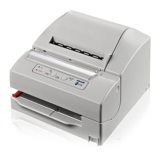
1.2.2 PR4 SR Printer PAPER ROLL COVER WINDOW RECEIPT OUTPUT SLOT CONSOLE FRONT COVER INSERTION SLOT FRONT INSERTION SLOT Figure 1-2 XYAA6336 Service Manual... - Page 9 Figure 1-3 Figure 1-4 Service Manual XYAA6336...
-
Page 10: Block Diagram
1.3 BLOCK DIAGRAM Double Roll Device Single Roll Device Journal rewinder (optional) Journal Cutter rewinder Receipt copy cutter Receipt Journal paper paper Single roll paper module module module Printing module MICR reader * Slip Paper Module Mechanical devices * = specific version MICR Main board Display &... -
Page 11: Internal Connections
1.4 INTERNAL CONNECTIONS PR4 Mechanical Devices Electrical Interconnections Note 2: Type: PAL MACH 111 for parallel interface. Note 1: On the board, a female connector is used for serial connections while a male connector is Type: ADM 202 JRW for serial interface. used for parallel connections. - Page 12 PR4 SR Mechanical Devices Out of paper switch adjustable rewinder guides Optional Journal 2nd copy journal rewinder Receipt 1st copy Cutter position switch adjustable paper guides Manual cutter Cutter motor Single roll motor Slip top of form sensor Slip Cheque top of...
-
Page 13: Power Supply Characteristics
1.5 POWER SUPPLY CHARACTERISTICS The machine must be equipped with a power supply of the following characteristics: DC VOLTAGE POWER 24 V +20 -10% 45 W (max. 75 W) The following power supplies are optionally available to the user: 1) External AC power supply: VOLTAGE POWER FREQUENCY... -
Page 14: Layout Of The Drawer And Display Connectors
1.6 LAYOUT OF THE DRAWER AND DISPLAY CONNECTORS By means of the drawer and display option it is possible to drive a client drawer and display. Refer to Chapter 8 for instructions on how to install the related card. • Drawer Connector Solenoid resistance 24 ohm min... -
Page 15: Serial Interface Connector Layout
1.7 INTERFACES 1.7.1 RS-232 Serial Interface Connector Layout • RS232 Connector - PIN functions Pin No Signal name Frame GND —- Transmitter data Receiver data Fix to ‘Space” level Space(+12) the host can receive data Mark(-12) the host cannot receive data When DTR/DSR control is selected, the printer transmits data after confirming this signal. -
Page 16: Iee 1284 Parallel Interface Connector Layout
1.7.2 IEE 1284 Parallel Interface Connector Layout Signal Source STROBX Host 2 to 9 DACX (0-7) Host/Printer ACKX0 Printer BUSYX Printer PAPEMX Printer SETOUX Printer AUTLFX Host FAULTX Printer IMPRAX Host SELINX Host 18 to 25 XYAA6336 Service Manual 1-11... -
Page 17: Installation
2. INSTALLATION 2.1 UNPACKING THE PRINTER It is suggested that you carefully open the printer packaging and store it in a safe place so that it can be used again if the printer needs to be transported to another site. The printer is protected by a polyethylene covering. -
Page 18: Checking The Packing
2.2 CHECKING THE PACKAGING CONTENTS 2.2.1 PR4 In addition to the printer, the packaging always contains two paper rolls, a ribbon cartridge, a client display support and two paper guides with a flange for 57 mm rolls. Depending on the order made by the client, the following options may be present: A Power cord B External power supply... -
Page 19: Pr4 Sr
2.2.2 PR4 SR The PR4 SR (Single Roll) packaging includes the printer, a printer roll, ribbon cartridge, client display support, two paper guides with two flanges, four spacers to form 139.7 mm., 114.3 mm., 82.5 mm. and 76.2 mm. long rolls, respectively. -
Page 20: Removing The Blockages Used For Transportation
2.3 REMOVING THE BLOCKAGES USED FOR TRANSPORTATION 2.3.1 PR4 • Remove the plastic strip from the front feed slot. • Open the front cover by turning it upwards. • Remove the cardboard that blocks the print head. • Close the printer cover. Figure 2-4 Service Manual XYAA6336... -
Page 21: Pr4 Sr
2.3.2 PR4 SR • Remove the plastic strip from the front feed slot. • Open the front cover by turning it upwards. • Remove the cardboard that blocks the print head. • Close the printer cover. Figure 2-5 XYAA6336 Service Manual... -
Page 22: Connections
2.4 CONNECTIONS 1. Attach the power cord to either the external (A) or internal (B) power supply. If the internal power supply is used, the power cord must have a 90 connector. 2. Attach the DC power cord to the related connector underneath the printer. -
Page 23: Settings To Be Made
2.5 SETTINGS TO BE MADE ACCORDING TO THE PAPER ROLLS USED (PR4 SR) The printer is designed to be able to use four types of paper rolls with the following widths: 76.2; 82.5; 114.3 and 139.7 mm. To insert the paper roll, take the rewinder which is... -
Page 24: Inserting The Rewinder For 76.2 Mm Rolls
2.5.1 Inserting the Rewinder for 76.2 mm Rolls PASSING BOSS Figure 2-8 Figure 2-9 Figure 2-10 BOSS WITH LONGER STOPPER Figure 2-11 Figure 2-12 Service Manual XYAA6336... -
Page 25: Inserting The Rewinder For An 82.5 Mm Roll
2.5.2 Inserting the Rewinder for an 82.5 mm Roll PASSING BOSS Figure 2-13 Figure 2-14 Figure 2-15 BOSS WITH SHORTER STOPPER Figure 2-16 Figure 2-17 XYAA6336 Service Manual... -
Page 26: Inserting The Rewinder For A 114.3 Mm Roll
2.5.3 Inserting the Rewinder for a 114.3 mm Roll BOSS WITH SHORTER STOPPER Figure 2-18 Figure 2-19 Figure 2-20 2-10 Service Manual XYAA6336... -
Page 27: Inserting The Rewinder For A 139.7 Mm Roll
2.5.4 Inserting the Rewinder for a 139.7 mm Roll Figure 2-21 Figure 2-22 Figure 2-23 XYAA6336 Service Manual 2-11... -
Page 28: Installing The Paper Guide
2.5.5 Installing the Paper Guide The paper guide must be installed when using 114.3 mm, 82.5 mm and 76.2 mm paper rolls. To install the paper guide for a 114.3 mm paper roll you need to remove the wider tab (see Figure 2-25). In the case of 82.5 and 76.2 mm paper rolls, detach both tabs. -
Page 29: Writing Position
2.5.6 Writing Position Ensure that the ribbon is completely positioned in the ribbon guide as shown in the figure. RIBBON GUIDE RIBBON PRINT HEAD Figure 2-27 XYAA6336 Service Manual 2-13... -
Page 30: Functional Checks
When flashing, indicates a mechanical error or a paper jam. LED 3 When on, (EPSON emulation) When flashing, (OLIVETTI emulation) indicates an almost out of receipt roll condition (when 50 to 150 mm of paper is still available, depending on the adjustment made). -
Page 31: Console Indications
3.2 CONSOLE INDICATIONS Different failures (errors or malfunctions) are signaled on the console in the following ways: • Error LED (LED 2) flashing • Error LED (LED 2) flashing + other LEDs on • Error LED (LED 2) on. The following table summarizes all the possible LED indications: Ref. - Page 32 For a detailed description of Ref. 7, press any key and the LEDs will assume one of the following configurations: Ref. Ref. Ref. Ref. Ref. LED Indications on the Console LED Indications on the Console LED Indications on the Console LED Indications on the Console LED Indications on the Console Failure Signaled...
-
Page 33: Slip Test
Activate the roll test mode as described in Section 4. Printer action: PR4: Continuous printing on receipt and journal. PR4 SR: Continuous printing on receipt Note: This cycle lasts approximately two hours for the receipt, four hours for the journal. -
Page 34: Setup And Adjustments
4. SETUP AND ADJUSTMENTS • Press key 1 one or more times until obtaining the light pattern corresponding to the operation to be carried out (refer to the table below indicating the Proceed as follows to setup and/or adjust the printer: correspondence between the light pattern and the •... -
Page 35: Operator Test
EMULATION: PR4 EMULATION PR4 SR ROLL WIDTH: 70 mm ROLL WIDTH: 140 mm BIT: 8 BAUD: 9600... -
Page 36: Selecting The Parameters
4.2.2 Selecting the Parameters After accessing Setup as explained in the section Accessing Setup (Section 4.2.1), the machine will print the first main menu. The following two alternatives are available: 1. Pressing key 2 - JOURNAL (select the menu), the machine will print the first parameter of this menu. -
Page 37: Set-Up Diagram (Olivetti Emulation)
4.2.3 SET-UP Diagram (Olivetti Emulation) When switching to the SET-UP mode, the printer can be programmed as indicated in the following diagram: enter EMULATION enter skip PR45 enter enter skip double roll version single roll version FORMAT skip skip enter... - Page 38 skip skip USER enter Nation enter NAZ.1 skip NAZ.2 skip NAZ.3 skip NAZ.4 skip NAZ.5 skip NAZ.nn enter enter enter enter enter enter skip enter skip skip 17.1 skip skip enter enter enter OPTION enter CUTTER enter skip enter enter skip skip enter...
-
Page 39: Set-Up Diagram (Epson Emulation)
4.2.4 SET-UP Diagram (EPSON Emulation) With the printer in the Setup mode, select the parameters by following the flow charts provided below. Service Manual XYAA6336... - Page 40 XYAA6336 Service Manual...
- Page 41 Service Manual XYAA6336...
- Page 42 XYAA6336 Service Manual...
-
Page 43: Disassembly/Reassembly Procedures
5. DISASSEMBLY/REASSEMBLY • Remove the ribbon cartridge and then remove the paper rolls by tearing them at their insertion PROCEDURES windows. 5.1 OVERVIEW • Extract the console by gently pushing it upwards. • Manually remove the Closed cover detection This chapter is divided into two parts which describe microswitches. - Page 44 PR4 SR RIBBON CARTRIDGE PAPER ROLL CLOSED COVER DETECTION MICROSWITCHES CONSOLE Figure 5-2 Service Manual XYAA6336...
- Page 45 • Remove the front cover by gently pressing on its • The cover of the paper rolls can also be removed two side tabs. manually by proceeding as shown in Figures 5-3, 5-4. Figure 5-3 XYAA6336 Service Manual...
- Page 46 PR4 SR Figure 5-4 Service Manual XYAA6336...
- Page 47 • To remove the print assembly from the case, proceed as shown in Figures 5-5, 5-6. The case must be removed from the base by manually sliding it upwards. Figure 5-5 XYAA6336 Service Manual...
- Page 48 PR4 SR • The arrows indicate the positions of the hooks that secure the frame to the base of the printer. Figure 5-6 Service Manual XYAA6336...
-
Page 49: Locating The Components On The Electronic Board (Serial Version)
LOCATING THE COMPONENTS ON THE ELECTRONIC BOARD (SERIAL VERSION) QS10 QS17 QS21 US13 US14 US19 US20 US18 XYAA6336 Service Manual... - Page 50 LEGEND: Ref. Description Fuse for the receipt, journal, slip and cutter motors Main fuse Carriage motor fuse Display/drawer board connector Needle head connector Slip motor connector Receipt motor connector Journal motor connector Cutter motor connector Slip photosensor connector (photo on the right edge of the slot) Paper photosensor connector (photo between the receipt and journal) Out of receipt and journal microswitch connector Power supply connector...
-
Page 51: Locating The Components On The Electronic Board (Parallel Version)
5.4 LOCATING THE COMPONENTS ON THE ELECTRONIC BOARD (PARALLEL VERSION) XYAA6336 Service Manual... - Page 52 LEGEND: Ref. Description F1, F2 Fuse from 1.6 to 125 V Fuse from 3.15 to 125 V Display/cassette card Needle print head Slip motor Slip photosensor (on the right-hand side of the slot) Paper detection photosensor (receipt and journal) Receipt and journal out of paper microsensor Power supply Micr card Console...
-
Page 53: Removing The Print Assembly
5.5 REMOVING THE PRINT ASSEMBLY • Remove screws 3 and 4 (Fig. 5.8). Separate the print unit from the paper feed unit by appropriately • Remove the case (Section 5.2). rotating them (Fig. 5.7). • Remove screws 1 and 2 shown in the figure so as •... - Page 54 PR4 SR Figure 5-10 Figure 5-11 Figure 5-12 5-12 Service Manual XYAA6336...
-
Page 55: Removing The Print Head
5.6 REMOVING THE PRINT HEAD • To completely extract the print head and related flat cable remove the board shown in Figure 5-14; • Remove the case (Section 5-2). gently bend this board so that it can be removed. • Remove screw 1. -
Page 56: Cutter On The Pr4
• Release the retension spring. 5.7 CUTTER ON THE PR4 • Unscrew the retension screw and the ground • Remove the case (Section 5). cable. • Proceed as explained in Section 5.2 to access the electronic board and then disconnect cutter motor connector J14. -
Page 57: Cutter On The Pr4 Sr
5.7.1 Cutter on the PR4 SR • Remove the case (Section 5.2). • Proceed as explained in Section 5.2 to access the electronic board and disconnect cutter motor connector J14. • Remove the assembly's two securing screws and lift it out of the printer. -
Page 58: Removing The Platen
5.8 REMOVING THE PLATEN • Remove the bracket and unscrew screws A, B, C. You can remove the platen in the direction of the • Remove the case (Section 5.2). arrow shown in the figure. • Remove the print assembly (Section 5.4). •... -
Page 59: Removing The Carriage Motor
5.9 REMOVING THE CARRIAGE MOTOR • Proceed as explained in Section 5.4 to access the print assembly. • Remove the case (Section 5.2). • After having removed the plastic board, remove screws A and B so that you can then remove the motor. -
Page 60: Removing The Ribbon Movement Pin
The pin is now free and can be removed by pulling 5.10 REMOVING THE RIBBON it upwards. MOVEMENT PIN • Remove the printer front cover. • Remove the flat cable guide board upwards (Fig.5-12), after having removed the bracket. Remove the exchanger using a pair of pliers (Fig.5-13). -
Page 61: Out Of Paper Microswitch Assembly
• Slide the assembly from its slot after having 5.11 OUT OF PAPER MICROSWITCH separated the cables and after detaching connector ASSEMBLY J20 from the electronic board. • Remove the case (Section 5.2). • After replacement, adjust the microswitch assembly by means of the appropriate screw until obtaining •... - Page 62 PR4 SR Figure 5-22 5-20 Service Manual XYAA6336...
-
Page 63: Removing The Rewind Clutch Assembly
5.12 REMOVING THE REWIND CLUTCH ASSEMBLY • Remove the case (Section 5.2). • Remove the timing belt to free the clutch assembly. To do so rotate the pulley gear by moving the belt sideways until it goes over the flange. 5.13 REMOVING THE DOCUMENT DETECTION PHOTOSENSORS •... -
Page 64: Removing The Slip Detection Photosensors
• Remove the paper guide plate in order to be able to (Section 6.9.1) access the photosensor assembly. PROCEED VERY CAREFULLY. SLIP DETECTION SLIP DETECTION PHOTOSENSORS PHOTOSENSORS SECURING SCREW SECURING SCREW PR4 SR PLATE Figure 5-25 5-22 Service Manual XYAA6336... -
Page 65: Adjustments
6. ADJUSTMENTS The following sections describe the adjustments to be made on the different printer assemblies. 6.1 ADJUSTING THE PLATEN ON THE BASIC STRUCTURE After replacing the platen check the parallelism between the platen and the basic structure. Parallelism with the carriage guide plate is obtained using a caliber and by adjusting the three securing screws (tolerance of + 0.1mm). -
Page 66: Adjusting The Parallelism And Print Head-Platen Distance
(Fig. 6-4) or according to the client's requirements. a probe, for a clearance of 0.33 - 0.37 mm between PR4 SR: Position the microswitch support as follows: the needle profile and platen code 474018S (Fig 6-2). for a 139.7 mm wide roll, all the way forwards towards the operator;... -
Page 67: Adjusting The Clearance Of The Document Insertion Slot
6.6 ADJUSTING THE CLEARANCE OF THE DOCUMENT INSERTION SLOT Using a specific probe, make sure that there is a clearance of 2.5 mm between the frame shield code 474030S and the frame in zama code 474017R. XYAA6336 Service Manual... -
Page 68: Adjusting The Paper Detection Photosensor
6.7 ADJUSTING THE PAPER DETECTION PHOTOSENSOR PLATE Once bar parallelism is performed, place an 0.5 mm thick plate between the rollers code 474041Z and code 474037M. Move the photo assembly code 474033R in contact with the plate and then tighten screw code 924917F. -
Page 69: Adjusting The Micr Motor Assembly Mesh
6.8 ADJUSTING THE MICR MOTOR ASSEMBLY MESH SCREWS With the screws frictioned, adjust the position of the MICR motor assembly so there is a clearance between the gears as shown in the figure and to avoid pointings during rotation, then tighten the screws. XYAA6336 Service Manual... -
Page 70: Adjustment Menu
6.9 ADJUSTMENT MENU To enter into the Adjustment Menu follow the instructions explained in Section 4. After the mechanical reset performed once the menu is entered, the console will assume the following configuration: Receipt LED Journal LED Slip LED ON LED Error LED Receipt LED Journal LED... -
Page 71: Photosensor Adjustments
6.9.1. Photosensor Adjustments After a reset the carriage moves to the far left position where the first phase of the adjustment procedure is carried out and which consists of multiple reads of the photosensors in out of paper conditions. The console assumes the following configuration during this phase: Flashing Receipt LED Slip LED... - Page 72 Console Configuration: Flashing Journal LED: Slip LED ON LED Error LED Journal LED Receipt LED Figure 6-9 Operator Action 1. Press the Journal key: Slip LED ON LED Error LED Receipt LED Journal LED Figure 6-10 Printer Action 1. Moves the paper in position, covering all the photosensors.
-
Page 73: Adjusting The Carriage
Photosensor Adjustment Errors Any error detected is signalled by the flashing of the console LEDs in the following way: Error LED Receipt LED Journal LED Slip LED Photosensor Error Blink Upper Blink Lower Blink Slip 1 Blink Slip 2 In case of error press the Journal key to return to the initial configuration. - Page 74 Error LED Receipt LED Journal LED Slip LED Error Blink Carriage reset error Otherwise: Operator Action 1. Open the front cover. Printer Action 2. Refit the cartridge. 1. The carriage moves to the mechanical reference 3. Close the cover. to drag the alignment roller. 2.
-
Page 75: Micr Adjustment
6.9.3 MICR Adjustment This adjustment must be made using the MICR calibration card code 474245 A (special check) on which the reference value is printed on the center bottom part of the card. Before beginning, make sure that the paper rolls are installed since the printer will have to print the values referring to the calibration card. - Page 76 Second part of the calibration procedure : Console configuration: Blinking Slip LED Slip LED ON LED Error LED Journal LED Receipt LED Operator action: Insert the check Printer action: Inserts the check Console configuration: Blinking Receipt LED: Slip LED ON LED Error LED Journal LED Receipt LED...
- Page 77 Calibration is performed by carrying out the second part of the calibration procedure FIVE TIMES. The operator must therefore insert the check five times. Upon completion the outcome of the calibration procedure will be printed: Calibration Ok A/D saturation Too many peaks Too many peaks (noise) Verify head Verify head connection (inverted)
-
Page 78: Lubrification
7. LUBRIFICATION LUBRIFICATE USING FOMBLYN Y06 OIL CODE 757283C (SUPPLIER: AUSIMONT, A MONTEDISON GROUP COMPANY) 1. CARRIAGE SLIDE SHAFT CODE 474064Y, 2 DROPS TO THE RIGHT AND 2 TO THE LEFT; THEN SOAK FELT CODE 474243 G IN 0.2 cc OF THE SAME OIL. LUBRIFICATE USING "MAGNALUBE"... -
Page 79: Installing The Drawer And Display Card Option
8. INSTALLING THE DRAWER AND DISPLAY CARD OPTION • Open the machine and insert the drawer and display drive card by following the procedure described in Section 5.4. • Insert the card in the slots on the base (see Figure 8-1) and then attach the connection cable to the main board.
Need help?
Do you have a question about the PR4 SR and is the answer not in the manual?
Questions and answers