Table of Contents
Advertisement
Lincoln Electric
This manual applies to
Part No.
K32061-11
REDI-MIG
K32062-11
REDI-MIG
K32062-2- AUP
REDI-MIG
Warranty Registration
www.mylincolnwarranty.com.au
Complete your warranty registration
online for your chance to win a Lincoln
Electric welding helmet valued at $299
– one winner drawn each month – and
the chance to win a Hot Lap with V8
Supercar driver Jason Bright*.
IM6016
*Competition terms and conditions can be viewed at:
www.mylincolnwarranty.com.au
May 2010
IM6016
®
Australasia
Description
Volts
Plus 215C
240
®
Plus 255C
240
®
Plus 255S
240
®
REDI-MIG
REDI-MIG
215C, 255C, 255S
Operator's Manual
Safety Depends on You
Lincoln Electric welders are designed and built with
safety in mind. However, your overall safety can be
increased by proper installation and thoughtful operation
on your part. Read and observe the general safety
precautions on page 2 and follow specific installation
and operating instructions included in this manual.
Most importantly, think before you act and be careful.
Plus 215C, 255C, 255S
®
Plus
®
Page 1
Advertisement
Table of Contents
Troubleshooting

Related Manuals for Lincoln Electric REDI-MIG Plus 215C


Summary of Contents for Lincoln Electric REDI-MIG Plus 215C
- Page 1 215C, 255C, 255S Lincoln Electric ® Operator’s Manual Australasia Safety Depends on You This manual applies to Lincoln Electric welders are designed and built with Part No. Description Volts safety in mind. However, your overall safety can be K32061-11 REDI-MIG Plus 215C ®...
-
Page 2: Table Of Contents
INDEX ARC WELDING SAFETY PRECAUTIONS WELDING, EMF & PACEMAKERS INSTRUCTIONS FOR ELECTROMAGNETIC COMPATIBILITY Section 1 INSTALLATION 1.1 Location 1.2 Connection to Mains Supply 1.3 Shielding Gas Supply (for the Gas Metal Arc Welding Process) 1.4 Gun and Cable Installation 1.5 Output Polarity Connection Section 2 OPERATING INSTRUCTIONS 2.1 Duty Cycle 2.2 Control Panel Section 3 SETTING UP FOR WELDING Section 4 WELDING 4.1 Changing Electrode Size and Type 4.2 Adjusting Spool Tension Section 5 LEARNING TO WELD 5.1 The Arc-Welding Circuit 5.2 The Self-Shielded (Gasless) FCAW Welding Arc 5.3 The GMAW (MIG) Welding Arc 5.4 Process Selection 5.5 Common Metals 5.6... -
Page 3: Arc Welding Safety Precautions
PROTECT YOURSELF AND OTHERS FROM POSSIBLE SERIOUS INJURY OR DEATH. READ AND UNDERSTAND BOTH THE SPECIFIC INFORMATION GIVEN IN THE OPERATING MANUAL FOR THE WELDER AND/OR OTHER EQUIPMENT TO BE USED AS WELL AS THE FOLLOWING GENERAL INFORMATION. ARC WELDING SAFETY PRECAUTIONS ARC RAYS can burn 1. a. T he electrode and work (or ground) circuits are 3. a. U se a shield with the proper filter and cover plates... - Page 4 FOR ENGINE CYLINDER may explode if powered equipment damaged 5. a. U se only compressed gas cylinders containing a. T urn the engine off before troubleshoot- ing and maintenance work unless the the correct shielding gas for the process used and maintenance work requires it to be properly operating regulators, designed for the gas running.
-
Page 5: Welding, Emf & Pacemakers
WELDING, EMF & PACEMAKERS All welders should follow safe practices that minimise their Welders with pacemakers exposure to electric and magnetic fields (EMF). There is no question that the fields in arc welding can interfere For welders wearing implanted pacemakers, safe welding with a pacemakers function. Generally the interference does not practices are particularly important and additional procedures permanently damage the pacemaker. Once the wearer leaves the should be followed by those who have decided to continue to arc welding environment or stops welding, the pacemaker returns... -
Page 6: Instructions For Electromagnetic Compatibility
INSTRUCTIONS FOR ELECTROMAGNETIC COMPATIBILITY purchaser/user shall ensure that other equipment being WARNING used in the environment is compatible. This may require additional protection measures; T he time of the day that welding or other activities are to be This welding machine must be used by trained operators carried out. only. Read this manual carefully before attempting to use the welding machine. The size of the surrounding area to be considered will depend on the structure of the building and other activities that are taking place. The surrounding area may extend beyond the boundaries Conformance of the premises. - Page 7 for selecting a QUALITY product by Lincoln Electric. We want you to take Thank You pride in operating this Lincoln Electric Company product - as much pride as we have in bringing this product to you! Please record your equipment identification information below for future reference. This information can be found on your machine nameplate. Model Name & Number ________________________________________ Code & Serial Number ________________________________________ Date of Purchase ________________________________________ Whenever you request replacement parts or information on this equipment, always supply the information you have recorded above. Read this Operator’s Manual completely before attempting to use this equipment. Save this manual and keep it handy for quick reference. Pay particular attention to the Safety Instructions we have provided for your protection. The level of seriousness to be applied to each is explained below: WARNING CAUTION This statement appears where the information must be This statement appears where the information must be followed exactly to avoid serious personal injury or loss followed to avoid minor personal injury or damage to this...
-
Page 8: Installation
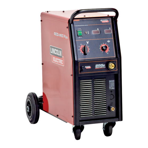
PRODUCT DESCRIPTION The REDI-MIG Plus family is the latest development in step controlled MIG welding machines designed and built by Lincoln Electric. ® Lincoln Electric’s new REDI-MIG Plus family comprises of three models in both compact and separate wire feeder. The REDI-MIG Plus ® ® 215C, 255C and 255S are for 240 volt supply. Excellent arc characteristics are provided for gas shielded and self shielded welding within the respective machine’s current ranges. 215C 255C 250S PWF4-S Specifications K32061-11 K32062-11 k32062-2-AUP K32066-1 Part No. Maximum Open Circuit Voltage 30-220A... -
Page 9: Shielding Gas Supply (For The Gas Metal Arc Welding Process)
T he regulator/flowmeter is adjustable. Set it for the flow 1.3 Shielding Gas Supply (For the Gas Metal rate recommended for the procedure and process being Arc Welding Process) used before starting to weld. O btain cylinder of appropriate type shielding gas for the 1.4 Gun and Cable Installation process being used. -
Page 10: Operating Instructions
Section 2 - OPERATING INSTRUCTIONS Welding voltage values for REDI-MIG Plus 215C, 255C, 255S ® WARNING REDI-MIG REDI-MIG REDI-MIG ® ® ® ® ® ® Plus 215C Plus 255C Plus 255S • D o not touch electrically live Position Volts Volts Volts parts or electrode with skin or wet clothing. 15.5V • I nsulate yourself from work 16.5V... - Page 11 Section 2 - OPERATING INSTRUCTIONS Please note - 9 not shown 7. Spool Gun Connection - 10. Output Terminals – Connection for the optional spool Dinse connection used to connect electrode cable and work return lead. gun on the 215C and 255C. FOR OUT POLARITY CONNECTION REFER TO SECTION 1.5 8. GAS PURGE/WIRE INCH – A two position toggle switch located on the REDI-MIG Plus 4s Use the gas purge ® 11. CONTROL CABLE OUTPUT CONNECTION - The control momentary toggle switch to operate the gas solenoid to purge cable connects to the output connection plug on the front of the air from the gas supply after connecting a new gas cylinder. Gas REDI-MIG Plus 255S power source above the output terminals.
-
Page 12: Setting Up For Welding
Section 3 - SETTING UP FOR WELDING The following items are required: Fit a spool of appropriate wire onto the spool so that it turns clockwise as the wire is fed. A reel of wire of suitable size and type. Carefully release the end of the wire from the spool ensuring that A suitable gun and cable assembly with a “Euro” connector the released end is held to stop the wire from unravelling. Cut off and the correct tip and, if necessary gas nozzle for the the end kink to give a smooth straight end of wire. consumable being used. (LINC Gun MIG gun is supplied). -
Page 15: Welding
Section 4 - WELDING A lso check electrode polarity, as different processes may WARNING require different polarities. N ote: Ensure that the correct gun liner and contact tip When the gun trigger is pressed (2T mode on REDI-MIG are used for different wire sizes and processes. Change 4s) or pressed and released the first time (4T mode on gun liner as necessary. See Section 6.5 Liner Removal, REDI-MIG 4s), the wire is at welding voltage. The wire... -
Page 16: The Self-Shielded (Gasless) Fcaw Welding Arc
W hen comparing the GMAW and FCAW processes, you 5.2 The Self-Shielded (Gasless) can see that the principal difference between the two lies in FCAW Welding Arc (DC-) the type of shielding used. GMAW uses gas for shielding, thus we have Gas Metal Arc Welding. FCAW uses the F igure 1 illustrates the action taking place in the self melting or burning of the core ingredients for shielding, and shielded gasless FCAW welding arc. It closely resembles is thus termed Self-Shielded Flux Cored Arc Welding. -
Page 17: Welding Techniques For The Self-Shielded (Gasless) Fcaw Process
Figure 4 5.7 Welding Techniques For The Self-Shielded (Gasless) FCAW Process Contact Tip F our simple manipulations are of prime importance when welding. With complete mastery of the four, welding will be easy. They are as follows: Wire Electrode 10 - 12 mm 1. The Correct Welding Position Electrical Stickout F igure 3 illustrates the correct welding position for (ESO) right handed people. (For left handed people, it is the opposite.) H old the gun (of the gun and cable assembly) in your right hand and hold the shield with your left hand. (Left... -
Page 18: Welding Techniques For The Gmaw (Mig) Process
Figure 7 Figure 8 5.9 Welding Techniques for the GMAW (MIG) Process F our simple manipulations are of prime importance when welding. With complete mastery of the four, welding will be easy. They are as follows: 1. The Correct Welding Position F igure 8 illustrates the correct welding position for right handed people. (For left handed people, it is the opposite.) W hen GMAW (MIG) welding on sheet metal, it is For the REDI-MIG... -
Page 19: Joint Types And Positions
3. The Correct Electrical Stickout (ESO) W hen you are sure that you can hold the correct electrical stickout, with a smooth “crackling” arc, start moving. Look T he electrical stickout (ESO) is the distance from the at the molten puddle constantly, end of the contact tip to the end of the wire. See Figure R un beads on a flat plate. Run them parallel to the top edge (the edge farthest away from you). This gives you O nce the arc has been established, maintaining the practice in running straight welds, and also gives you correct ESO becomes extremely important. The ESO... -
Page 20: Fillet Welds
Figure 13 T he important thing is to continue lowering the entire arm as the weld is made so the angle of the gun does not change. Move the electrode wire fast enough that the slag does not catch up with the arc. Vertical-down welding gives thin, shallow welds. It should not be used on heavy material where large welds are required. Figure 16 5.13 Fillet Welds W hen welding fillet welds, it is very important to hold the wire electrode at a 45° angle between the two sides or the metal will not distribute itself evenly. The gun nozzle is generally formed at an angle to facilitate this. See Figure 14. -
Page 21: Maintenance
To Reduce Spatter (in order of importance): 1. Decrease torch angle. 2. Increase stickout. 3. Decrease voltage. 4. Decrease WFS (wire feed speed. 5. Decrease travel speed. To Eliminate Stubbing* (in order of importance): 1. Increase voltage 1. Increase voltage. 2. Decrease WFS (wire feed speed) 3. Decrease stickout 2. Increase torch angle. 4. Increase torch angle 3. Decrease stickout. * S tubbing occurs when the electrode drives through the 4. Increase WFS (wire feed speed). molten puddle and hits the bottom plate tending to push 5. Decrease travel speed. the gun up. 6. Check for correct gas, if used. Proper Gun Handling To Correct Poor Penetration (in order of importance): M ost feeding problems are caused by improper handling of the gun cable or electrodes. -
Page 22: Liner Removal, Installation And Trimming Instructions For Linc Gun 240 & 360 Torch
I nsert a new untrimmed liner into the connector end of the 6.5 Liner Removal, Installation and Trimming cable. ® Instructions for LINC Gun 240 & 360 Torch F ully seat the liner bushing into the Euro connector. Tighten the liner nut cap on the brass cable connector. The N ote: The variation in cable lengths prevents the inter- contact tip holder, at this time, should not be installed onto changeability of liners between guns. Once a liner has the end of the gun tube. - Page 23 Section 8 - GROUND TEST PROCEDURE The following procedures refer to the REDI-MIG 210c & 250c ® Disconnect the PCB plug. WARNING S witch the control rotary switch to position ‘one’ (1) and switch the on/off switch to on. This procedure is only suitable for applications using DC mega testers up to 500V.
- Page 24 Section 9 - TROUBLESHOOTING WARNING • H ave an electrician install and service this equipment. • T urn the input power off at the fuse box and unplug the ma- chine before working on equip- ment. ELECTRIC • D o not touch electrically hot SHOCK parts. can kill Problem Possible Cause What To Do Rough wire feeding or Gun cable kinked and/or twisted. Inspect gun cable and replace if necessary. wire not feeding but drive rolls turning. Wire jammed in gun and cable. Remove wire from gun and cable - feed in new wire.
-
Page 25: Troubleshooting
TROUBLESHOOTING What To Do Problem Possible Cause No wire feed, although arc volt- Defective wire feed motor or wire drive con- Measure the voltage between the motor leads age is present. trol PC board. (54) and (53) when the Gas Purge/Wire Inch toggle switch is pressed downwards. If this voltage is over 10V DC, replace the wire feed motor. If no voltage is registered, replace the wire drive PCB. (Refer PCB replacement procedure on page 19). No control of wire feed. Defective wire drive control PC board. Replace PCB. (Refer PCB replacement procedure on page 19). No wire feed and no arc voltage. Overtemperature protection circuit actuated Allow machine to cool down and reduce on Pilot light indicates input power due to overload or short. (Overtemperature time and/or wire feed speed. - Page 26 LIMITED WARRANTY IM6016 (1/06) STATEMENT OF LIMITED WARRANTY CONDITION OF WARRANTY The Lincoln Electric Company (Australia) Pty Limited (“Lincoln”) warrants all new TO OBTAIN WARRANTY COVERAGE: machinery and equipment (“goods”) manufactured by Lincoln against defects in The purchaser must contact Lincoln or Lincoln’s Authorised Service Facility about any workmanship and material subject to certain limitations hereinafter provided. defect claimed under Lincoln’s warranty. This warranty is void if Lincoln or its Authorised Service Facility finds that the Determination of warranty on welding and cutting equipment will be made by Lincoln or equipment has been subjected to improper installation, improper care or abnormal Lincoln’s Authorised Service Facility. operations. WARRANTY REPAIR PERIOD OF WARRANTY “LINCOLN BRANDED GOODS” If Lincoln or Lincoln’s Authorised Service Facility confirms the existence of a defect covered by this warranty, the defect will be corrected by repair or replacement at The period from the commencement of the warranty in respect of goods covered by Lincoln’s option. this warranty shall be as follows: At Lincoln’s request, the purchaser must return, to Lincoln or its Authorised Service Three Years Facility, any “Goods” claimed defective under Lincoln’s warranty. All Lincoln welding machines, wire feeders and plasma cutting machines unless listed below. FREIGHT COSTS The purchaser is responsible for shipment to and from the Lincoln Authorised Service Two Years Facility. All Weldanpowers, Rangers and Italian Invertec welders. WARRANTY LIMITATIONS One Year Certain conditions warranties and obligations are implied by law (for example under Italian Plasmas. the Trade Practices Act 1974) and cannot be excluded or modified (“the statutory • A ll water coolers (internal and external). warranties”).
Need help?
Do you have a question about the REDI-MIG Plus 215C and is the answer not in the manual?
Questions and answers