Table of Contents
Advertisement
Quick Links
IMPORTANT NOTE:
The +12V for the
controller should NOT
be taken from the same
circuit as the Fan Power
12V as this can cause
the fan to cycle on and
off.
Fused battery 12V
GAUGE
(not used in
GAUGE
sender only
or BIM
application)
+12V
Required components for installation:
The PAC-2750 is shipped with necessary components for use with a single fan on a gauged system. These parts include:
1
PAC-2750 module
1
RLY-3 relay with wiring harness
1
BIM data cable
1
Instruction manual
For some options of the PAC-2750, additional components are required. These are listed below.
- Second RLY-3 assembly (needed for dual fan or two speed fan operation)
- 300ºF sender Dakota Digital temp sender (for operation without a gauge)
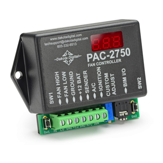
ELECTRIC COOLING FAN CONTOLLER
www.dakotadigital.com
techsupport@dakotadigital.com
Choose
option
below
SENDER
(not used in BIM
application)
Fan
Fan
High
Low
-
-
+
+
FAN2
FAN1
-
-
two separate fans
PAC-2750
605-332-6513
PAC-2750
FAN CONTROLLER
Fan
Fan
High
Low
+12V
-
-
+
+
FAN
HIGH
LOW
-
dual speed fan
To gauge control box
or another BIM
+12V with key ON
A/C clutch cycle switch (+12V trigger)
Fan
Fan
High
Low
+12V
-
NOT
CONNECTED
Fan
PWR
+
+12V
FAN
-
single fan
MAN# 650411:B
Advertisement
Table of Contents

Related Manuals for Dakota Digital PAC-2750


Summary of Contents for Dakota Digital PAC-2750
- Page 1 Required components for installation: The PAC-2750 is shipped with necessary components for use with a single fan on a gauged system. These parts include: PAC-2750 module RLY-3 relay with wiring harness BIM data cable Instruction manual For some options of the PAC-2750, additional components are required.
- Page 2 The fan will turn on and run continuously if the sender is disconnected as a failsafe. Always keep clear of the fan unless the battery is disconnected. When entering setup mode with a VHX or VFD gauge system and the PAC-2750 connected with a BIM cable the fan will begin running continuously after a 2 minute delay.
- Page 3 Set Up Press and hold SW2, then turn the key on. Release SW2, then press and release SW1 to move onto the next step. To select temperature scale to use, press and hold SW1 to select F (Fahrenheit) or press and hold SW2 for C (Celsius). Hold the switch for longer than one second to select. Once a temperature scale is selected, the display will flash and go on to next setting.
- Page 4 Option No gauge, dedicated Dakota Digital sender only Dakota Digital individual temp gauge with sender Dakota Digital instrument cluster with control box (ver. STR-D or later, older versions use CUS) Stewart Warner gauge and sender Classic gauge and sender VDO gauge and sender...
- Page 5 The current temperature reading can be displayed on the unit at anytime during normal operation without going into the diagnostic mode. Simply press and hold SW1 while the key is on and the PAC-2750 is not in setup or diagnostic mode.
- Page 6 Hold SW1, if temperature read is lower than expected or (gauge setup) doesn’t match gauge, redo setup. Wrong sender used For sender only applications ONLY a Dakota Digital (for no gauge setup) 300ºF sender can be used. Other senders may not give a correct temperature reading.
-
Page 7: Service And Repair
Any action for breach of any warranty hereunder, including any implied warranty of merchantability, must be brought within a period of 24 months from date of original purchase. No person or representative is authorized to assume, for Dakota Digital, any liability other than expressed herein in connection with the sale of this product.
Need help?
Do you have a question about the PAC-2750 and is the answer not in the manual?
Questions and answers