Advertisement
Advertisement
Table of Contents

Related Manuals for Carrier 40KMC---N


Summary of Contents for Carrier 40KMC---N
- Page 1 40KMC---N INSTALLATION MANUAL...
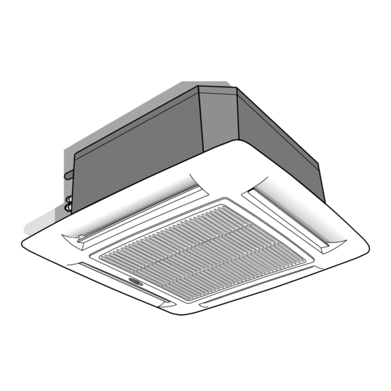
- Page 2 Split system “Global cassette” indoor unit IR Remote Control “Room Controller” “Zone Manager” The unit can be used with infrared Remote Control, with the Carrier “Room Controller” or “Zone Manager”. Infrared control installation instructions are contained in the unit instruction and maintenance manual.
-
Page 3: Dimensions And Weight
40KMC---N Dimensions and weight 40KMC 012N - 018N - 024N Ø 25 40KMC 028N - 036N - 048N - 060N Ø 100 40KMC---7N Unit 17,5 Frame / Grille assembly GB - 2... -
Page 4: Technical Data
40KMC---N Technical data E N G L I S H Table I: Nominal data POWER INPUT (WATT) POWER INPUT (WATT) Cooling only Heat pump standard Cooling Heating Sizes standard Cooling Heating Sizes 40KMC012-7N 40KMC012-7N 40KMC018-7N 40KMC018-7N 40KMC024-7N 40KMC024-7N 40KMC028-7N 40KMC028-7N... -
Page 5: General Information
• Choose an area free from obstructions which may cause uneven the indoor unit of a residential split system consisting of two air distribution and/or return. Carrier manufactured units. Do not connect this unit to any other manufacturer's outdoor unit. • Consider using an area where installation is easy. - Page 6 40KMC---N Warnings: avoid... E N G L I S H ... any obstruction of the unit air intake or supply grilles..exposure to direct sunshine, when the unit is operating in the cooling mode; always use shutters or shades.
- Page 7 40KMC---N Warnings: avoid..slack on electrical connections..unnecessary turns and bends in connection pipes (see ... disconnecting refrigerant connections after installation: this will installation manual of outdoor unit). cause refrigerant leaks. Excessive connection pipe length (see installation manual of outdoor unit).
- Page 8 40KMC---N Installation E N G L I S H Prior to installation Threaded hangers "T" bar (to be removed) First position the refrigerant lines, as described in the chapter “Refrigerant connections”. It is advisable to place the unit as close as possible to the Remove the “T”...
- Page 9 40KMC---N Installation Indoors Outdoors Frame support brackets Making the hole for connection pipes in the external wall Installation of grille/frame assembly • After positioning the units and determining the connection position, Carefully unpack the assembly and check for damage sustained in make a 70 mm Ø...
-
Page 10: Refrigerant Connections
40KMC---N Refrigerant connections E N G L I S H IMPORTANT: Pipe connection to the unit During the unit installation make first refrigerant connections Use two wrenches to tighten all connections. and then electrical connections. If unit is uninstalled first Insufficient tightening torque could cause a refrigerant leak from disconnect electrical cables, then refrigerant connections. -
Page 11: Electrical Connections
40KMC---N Electrical connections CONTROL PANEL CONTROL PANEL mod. 12 - 18 - 24 mod. 28 - 36 - 48 - 60 Condenser Relay board (only on A. Electric heater supply Fan connector (under main terminal models with electric connection LED/RECEIVER connector... - Page 12 40KMC---N Electrical connections E N G L I S H Cooling only - 40KMC012N WARNING: The ground wire for the indoor unit-outdoor unit connection cable must be clamped to a soft copper tin- plated eyelet terminal with M4 screw hole.
- Page 13 40KMC---N Electrical connections Heat pump - 40KMC012N WARNING: The ground wire for the indoor unit-outdoor unit connection cable must be clamped to a soft copper tin- plated eyelet terminal with M4 screw hole. Indoor and outdoor units interconnection (mm Model 40KMC012N 3G2.5...
- Page 14 40KMC---N Electrical connections E N G L I S H Cooling only - 40KMC 018N, 024N, 036N, 048N, 060N Indoor and outdoor units interconnection (mm Model 40KMC 018, 024N Disconnected 40KMC 036, 048, 060N Heat pump - 40KMC 018N, 024N, 036N, 048N, 060N...
-
Page 15: Cable Passage
40KMC---N Electrical connections Wiring diagram - Cooling only or heat pump units with electric heater LEGEND FACTORY WIRING FIELD WIRING CONNECTOR TERMINAL ON COMPONENT TERMINAL ON STRIP NORMALLY CLOSE CONTACT NORMALLY OPEN CONTACT CAPACITOR SENSOR TRANSFORMER FAN CAPACITOR SAFETY MICRO FLOAT... - Page 16 40KMC---N Fresh air renewal and conditioned air supply to an adjacent room E N G L I S H Ø Duct connection flange Clip 6 mm neoprene gasket Insulated flexible duct Model 012N-018N-024N 028N-036N-048N-060N Fresh air intake Ø A Conditioned air supply to an...
- Page 17 40KMC---N Fresh air renewal and conditioned air supply to an adjacent room Diagram of conditioned air supply to an adjacent room: one louvre closed 24/28 113, 9 Air flow Supply air duct to adjacent room In case of two louvres closed, the fresh air flow towards the adjacent room is 50% higher compared with only one louvre closed (with equal static external pressure).
-
Page 18: System Configuration
Default address is both indoor units. “HP”: heat pump “UCFG” Refer to the specific instruction sheet “AC”: cooling only 40 with increase of 1 Unit CCN address (Carrier Confort Network) “UAdr” Default = 1. 40 with increase of 1 Number of zone. “ZONE”... -
Page 19: Operating Test
40KMC---N Operating test, address switch and address selector Table VIII Shown on display Description Options Address indoor unit A. See paragraph "address selector " “A”: unit A “CH” “b”: unit B Address indoor unit B. See paragraph "address selector "... - Page 20 40KMC---N Fault code, button T: “EMERGENCY” and guide for the owner E N G L I S H Warning lamps and emergency button P : Green LED T : “Emergency” Q : Red LED R : Yellow LED S : Remote control signal receiver Fault code Button T: “EMERGENCY”...
- Page 21 L010127H26 - 1205 Via R. Sanzio, 9 - 20058 Villasanta (MI) Italy - Tel. 039/3636.1 The manufacturer reserves the right to change any product specifications without notice. December, 2005. Printed in Italy...
Need help?
Do you have a question about the 40KMC---N and is the answer not in the manual?
Questions and answers
محتاج ريموت لهذا الجهاز
The Carrier model 40KMC---N can be used with an infrared remote control, the Carrier “Room Controller,” or the “Zone Manager.” The installation instructions for the infrared remote control are in the unit instruction and maintenance manual, while installation instructions for other remote controls are in their respective manuals. These manuals are supplied with the remote controls.
This answer is automatically generated