Table of Contents
Advertisement
Advertisement
Table of Contents

Subscribe to Our Youtube Channel
Related Manuals for Carrier 40KQV050-7


Summary of Contents for Carrier 40KQV050-7
- Page 1 40KQV INSTALLATION MANUAL...
-
Page 2: Table Of Contents
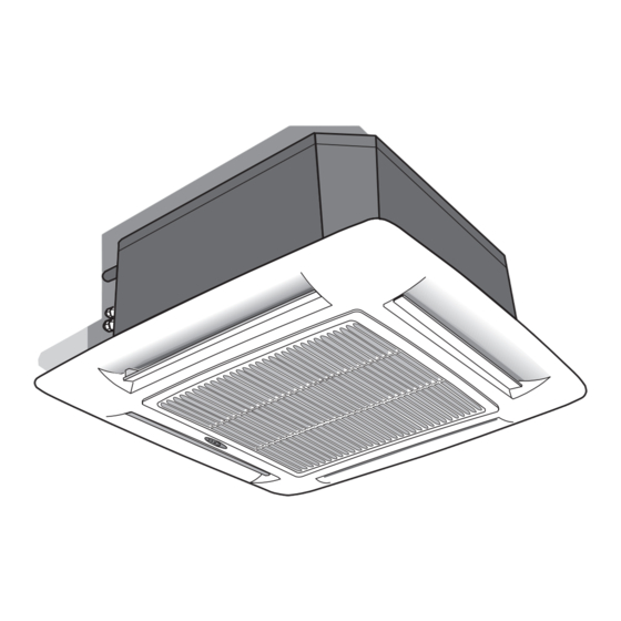
Split system “Global cassette” indoor unit IR Remote Control “Room Controller” “Zone Manager” The unit can be used with infrared Remote Control, with the Carrier “Room Controller” or “Zone Manager”. Infrared control installation instructions are contained in the unit instruction and maintenance manual. -
Page 3: Dimensions And Weight
40KQV Dimensions and weight 40KQV050 Ø 25 40KQV 080 - 110 - 130 Ø 100 40KQV Unit Frame / Grille assembly GB - 2... -
Page 4: Technical Data
40KQV Technical data E N G L I S H Table I: Nominal data POWER INPUT (WATT) Heat pump Unit Cooling Heating 40KQV050 40KQV080 40KQV110 Note: For power supply wire size and delay type fuses, refer to the outdoor unit 40KQV130 installation instructions. -
Page 5: General Information
• This installation manual describes the installation procedures of • Consider using an area where installation is easy. the indoor unit of a residential split system consisting of two Carrier • Choose a position that allows for the clearances required. -
Page 6: Warnings: Avoid
40KQV Warnings: avoid... E N G L I S H ... exposure to direct sunshine, when the unit is operating in the ... any obstruction of the unit air intake or supply grilles. cooling mode; always use shutters or shades.. -
Page 7: Installation
40KQV Warnings: avoid..slack on electrical connections..unnecessary turns and bends in connection pipes (see ... disconnecting refrigerant connections after installation: this will installation manual of outdoor unit). cause refrigerant leaks. Excessive connection pipe length (see installation manual of outdoor unit). - Page 8 40KQV Installation E N G L I S H Prior to installation Threaded hangers "T" bar (to be removed) First position the refrigerant lines, as described in the chapter “Refrigerant connections”. It is advisable to place the unit as close as possible to the Remove the “T”...
- Page 9 40KQV Installation Indoors Outdoors Frame support brackets Making the hole for connection pipes in the external wall Installation of grille/frame assembly • After positioning the units and determining the connection position, Carefully unpack the assembly and check for damage sustained in make a 70 mm Ø...
-
Page 10: Refrigerant Connections
40KQV Refrigerant connections E N G L I S H IMPORTANT: Pipe connection to the unit During the unit installation make first refrigerant connections Use two wrenches to tighten all connections. and then electrical connections. If unit is uninstalled first Insufficient tightening torque could cause a refrigerant leak from disconnect electrical cables, then refrigerant connections. -
Page 11: Electrical Connections
40KQV Electrical connections CONTROL PANEL CONTROL PANEL mod. 050 mod. 080 - 110 - 130 Condenser Transformer Fan connector B. Outdoor unit connection (under main terminal Holes for fixing panel in LED/RECEIVER connector board) position Float connector Ground connection screws Emergency push-button Pump connector GMC board (inverter) -
Page 12: Cable Passage
40KQV Electrical connections E N G L I S H Heat pump - 40KQV 050, 080, 110, 130 Minimum section of connecting cable conductors for inside and outside units (mm 2 ) Models 40KQV 050, 080, 110, 130 Terminal box legend, all models 10 80 Earth Live connection indoor/outdoor unit... -
Page 13: Fresh Air Renewal And Conditioned Air Supply To Adjacent Room
40KQV Fresh air renewal and conditioned air supply to an adjacent room Ø Duct connection flange Clip 6 mm neoprene gasket Insulated flexible duct Model 080 - 110 - 130 Fresh air intake Conditioned air supply to an Ø A adjacent room Polystyrene partition Baffle... -
Page 14: Operating Test
40KQV Fresh air renewal and conditioned air supply to an adjacent room E N G L I S H Diagram of conditioned air supply to an adjacent room: one louvre closed 24/28 113, 9 Supply air duct to adjacent room Air flow In case of two louvres closed, the fresh air flow towards the adjacent room is 50% higher compared with only one louvre closed (with equal static external pressure). -
Page 15: Address Selector And Fault Code
40KQV Address selector and fault code Address selector Note: When 30 seconds have elapsed and no buttons have been pressed, the remote control will automatically exit the If you are installing two indoor units in the same room and you want configuration menu and the procedure has to be restarted. - Page 16 40KQV Unit warning lights and guide for the owner E N G L I S H P : Green LED Q : Red LED R : Yellow LED S : Remote control signal receiver T : “Emergency” - Automatic mode Button T: “EMERGENCY”...
- Page 17 L010125H95 - 0605 Via R. Sanzio, 9 - 20058 Villasanta (MI) Italy - Tel. 039/3636.1 The manufacturer reserves the right to change any product specifications without notice. June, 2005. Supersedes April, 2005. Printed in Italy...
Need help?
Do you have a question about the 40KQV050-7 and is the answer not in the manual?
Questions and answers