Table of Contents
Advertisement
Quick Links
Table of Contents
FORWARD from Mike Adams ..................................
THE BASICS
How to use this Manual .......................................
Setup and Connections ........................................
Overview and Features ........................................
Signal Flow ....................................................................
Basic Operation .........................................................
A. Oscillator Section ................................................
B. Filter Section ...........................................................
C. Envelope Generators Section .....................
D. Modulation Section ...........................................
E. Output Section .....................................................
F. Keyboard & LH Controllers ...........................
G. Input/Output Panel ............................................
H. Interface Panel ......................................................
Stage Edition
THE USER INTERFACE
4
Preset Mode ..........................................................................
Master Mode .........................................................................
5
A. Menus ........................................................................
5
B. Advanced Presets ................................................
7
C. System Exclusive .................................................
9
D. System Utilities .....................................................
10
Performance Sets ................................................................
How the LP handles MIDI .............................................
11
APPENDICES
13
A - Master Mode Menu Flow Chart ......................
15
B - The Calibration Preset ...........................................
17
C - Tutorial .............................................................................
18
D - MIDI Implementation .............................................
19
E - Service & Support Information .........................
20
F - Caring for the Little Phattty .................................
21
H - Specifi cations ...............................................................
GLOSSARY ......................................................................................
23
25
25
30
33
35
42
44
46
47
48
53
54
54
55
57
58
Page 3
Advertisement
Table of Contents

Related Manuals for Moog Stage Edition


Summary of Contents for Moog Stage Edition
-
Page 1: Table Of Contents
E – Service & Support Information ......G. Input/Output Panel ..........F – Caring for the Little Phattty ......... H. Interface Panel ............G – Using the CP-251 with the Little Phatty ..H – Specifi cations ............... GLOSSARY ..................Page 3... -
Page 2: Forward From Mike Adams
The Little Phatty Stage Edition is a great performance synth. If you read through this manual carefully and incorporate all the Little Phatty has to offer in your rig you may fi nd that you do not need another synth for live performance. -
Page 3: How To Use This Manual
First time users should check out the tutorial in Appendix C, where you will fi nd an explanation of sound and subtractive synthesis. For those interested MIDI interface specifi cs, see the section titled “How the Little Phatty handles MIDI”, as well as the MIDI Interface Specifi cation, Appendix D. - Page 4 You will need a sturdy keyboard stand or table that will support a 22 lb. analog synthesizer and will not topple if you play hard. Use caution when lifting the Little Phatty out of the carton, and be sure to save the carton and all packing material in case you need to ship the Little Phatty for any reason.
-
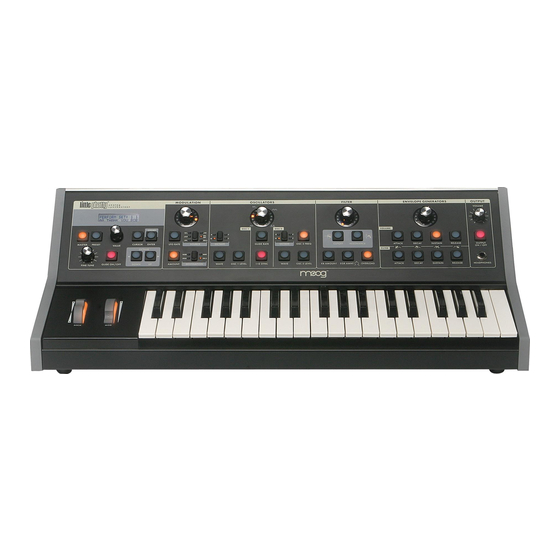
Page 5: Overview And Features
Overview and Features The Little Phatty (LP for short) is a monophonic analog synthesizer that is a descendant of the classic Minimoog Model D. The LP features 2 ultra-stable oscillators, a genuine Moog 24dB/Octave low pass fi lter, two 4-stage analog envelope generators and a fl exible modulation matrix. - Page 6 2. Audio jacks – provides monophonic audio input and audio output connections. The Audio Input jack allows external signals to be processed by the Little Phatty. 3. Control Voltage jacks – provides Control Voltage/Expression Pedal inputs for Pitch, Filter, and Volume parameters, and a keyboard gate input to trigger the envelope generators with a footswitch or gate signal.
-
Page 7: Signal Flow
To understand the operation of the Little Phatty, take a look at the diagram below. The diagram shows the fl ow of the audio, control voltage and modulation signals in the Little Phatty. Heavy lines are used to indicate audio signals, which fl ow from left to right. Lighter lines indicate the control voltages (CV’s), which fl ow from the top and bottom. -
Page 8: Basic Operation
In the Stage Edition, RAC provides responsive analog control for the Osc 1 & 2, Filter Cutoff, Filter Resonance, EG Amount, Overload and Filter EG Sustain parameters. -
Page 9: The Components
Left-Hand controls, the Input/Output Side Panel, and the User Interface section. A. The Oscillator Section The Oscillators are the main sound source of the Little Phatty. The oscillators in the LP are analog Voltage Controlled Oscillators (VCOs) that feature a temperature regulation circuit that provides them with excel- lent tuning stability. - Page 10 LP User’s Manual - The Components Waveform: Each oscillator has a switch labeled WAVE that allows the analog edit control to modify the waveform. The waveform is continuously variable from triangle, to sawtooth, to square, to rectangular. The waveform is morphed gradually from one to another as the value control is rotated. The legend around the analog edit control for the oscillator section indicates the knob positions to obtain the triangle, sawtooth, square and skinniest pulse waveforms.
-
Page 11: Filter Section
LP User’s Manual - The Components B – The Filter Section Filters are used for adjusting the timbre of an audio signal. Filters modify sound by attenuating some fre- quencies while allowing others to pass through unaffected. An important term to understand regarding fi lters is “Cutoff Frequency”. - Page 12 LP User’s Manual - The Components Finally, the OVERLOAD parameter allows you to set the amount of signal clipping from none to soft to hard clipping as the amount is increased. The results you get with OVERLOAD will depend on the settings of the oscillator waves and levels, and the fi lter cutoff and the fi lter resonance settings in addition to Overload amount.
-
Page 13: Envelope Generators Section
(see ADSR Envelope Signal below). The Little Phatty has one EG dedicated to the fi lter (to control the cutoff frequency), and one EG dedicated to the amplifi er (to control the volume). - Page 14 LP User’s Manual - The Components Envelope Generator Section Controls: Attack: When the ATTACK switch is selected, the analog edit control is used to adjust the Attack time of the corre- sponding envelope from 1 msec to 10 seconds. Decay: When the DECAY switch is selected, the analog edit control is used to adjust the Decay time of the cor- responding envelope from 1 msec to 10 seconds.
-
Page 15: Modulation Section
LP User’s Manual - The Components D – The Modulation Section Modulation is the heart of making interesting sounds with analog subtractive synthesis. The LP’s Modulation section opens up a world of modulation possibili- ties that were not available on the original Minimoog. The Modulation section allows you to select from six modulation sources, four destinations, and set the modulation amount. -
Page 16: Output Section
LP User’s Manual - The Components E – The Output Section The Little Phatty has a single monophonic audio output. The level of the audio output is adjusted by the Volume Control. An On/Off switch allows you to turn off the output signal while keeping the Headphone signal active. -
Page 17: Keyboard & Lh Controllers
LP User’s Manual - The Components F – Keyboard and Left-Hand Controllers The Little Phatty has a 37-note keyboard (3 octaves, C to C). When combined with the OCTAVE but- tons, the keyboard has a playable range of 7 octaves. -
Page 18: Input/Output Panel
LP User’s Manual - The Components G – Input/Output Panel The Side Panel provides all of the input and output connects. In addition to the Audio Out- put, there are CV and Gate inputs, connections for MIDI, and the power connector and power switch. -
Page 19: Interface Panel
Pressing the MASTER switch places you in Master mode. In this mode, the VALUE knob is used to scroll through the Master mode menus for the Little Phatty. For a list of the Master mode menus, see page 25. Preset: Pressing the PRESET switch places you in Preset mode. - Page 20 LP User’s Manual - The Components Fine Tune: The FINE TUNE control is used to tune the Little Phatty’s oscillators + /– 3 semitones for matching an external reference pitch. Glide On/Off: The GLIDE ON/OFF switch enables or disables the glissando effect between notes. Glide is ON when the switch LED is lit.
-
Page 21: Preset Mode
LP User’s Manual - The User Interface Preset Mode Preset mode is the default mode when the LP is powered on. Preset Mode is used to access presets and provide control for editing, naming and storing sounds. Preset sounds are selected using the VALUE knob. As the VALUE knob is advanced, the next preset appears in the display and is immediately available to be auditioned (you do not need to ‘activate’... - Page 22 LP User’s Manual - The User Interface When you press STORE, the LCD will display the ‘PRESET STORED’ message. Changing A Preset Name Changing a preset name is simple. Characters in a name are individually selected by moving the cursor to the desired location and scrolling through the character list.
-
Page 23: Master Mode
LP User’s Manual - The User Interface Master Mode Master mode accesses the global settings and Advanced Preset settings for the Little Phatty, and the routines for sending and receiving data. To enter master mode, press the MASTER button. By default, the fi rst master menu entry is Performance Sets. - Page 24 LP User’s Manual - The User Interface ADVANCED PRESET: Advanced Presets is a set of menus that allows you to access additional parameters for each preset. These parameters are stored individually for each preset. There are ten Advanced Preset menus available: - Filter Poles (1-4) - EGR Release...
- Page 25 LP User’s Manual - The User Interface MIDI CHANNELS IN AND OUT: This menu is used to select the LP’s MIDI In and Out channels. The LP can only send and receive on one channel at a time, but each channel can be set independently.
- Page 26 LP User’s Manual - The User Interface LOCAL CONTROL/FINE TUNE (con’t): When the Tune parameter is set to AUTO, the AutoTune function is engaged and the display changes as shown. AutoTune works to keep the LP in tune by automatically making fi ne adjustments to the Fine Tuning CV.
- Page 27 LP User’s Manual - The User Interface PRECISION MODE: Precision Mode is a feature that allows precision editing of LP param- eters using the VALUE knob. Each LP parameter stored has a value from zero to 4095. In Precision Mode that value is displayed on the second line on the screen.
-
Page 28: Advanced Presets
LP User’s Manual - The User Interface B. Advanced Preset menus The Advanced Preset menu provides a set of additional programming parameters for each preset. These parameters are stored individually for each preset. FILTER POLES: This menu allows you choose the number of Filter Poles for the preset. - Page 29 LP User’s Manual - The User Interface MOD SOURCE 5 (MOD SRC 5): This menu allows you to select one of two modulation options that will be used when the FILT ENV source is selected on the front panel (Modulation Source 5). The Filter Envelope (FILT) is the default source, but Sample &...
- Page 30 LP User’s Manual - The User Interface POT MAPPING: The Pot Mapping menu allows you to make arbitrary MIDI Continuous Controller (CC) assignments to each of the four Analog Edit knobs on the front panel (MOD, OSC, FILT, and EGR). Additionally, the four knobs can be individually programmed to provide internal, external, or combined MIDI control.
-
Page 31: System Exclusive
LP User’s Manual - The User Interface C. SYSEX (System Exclusive) menus SysEx menus are a set of commands to transmit and receive selected presets, bulk dumps and fi rmware dumps. To enable SysEx menus, press the CURSOR button. This will highlight the menu options shown on the second line of the display. - Page 32 The LP is able to receive System Exclusive data at any time without any special prior setup. SysEx fi les are recognized and received automatically when a SysEx data transfer is initiated. The Little Phatty’s LCD screen will display the status of SysEx data transfers as follows: SINGLE PRESETS: The LP will briefl y display a ‘RECEIVING SINGLE PRESET’...
-
Page 33: System Utilities
LP User’s Manual - The User Interface D. System Utilities menus System Utilities provides a set of useful commands, including a command to send an “All Notes Off ’ mes- sage, a command to perform an operating system reboot, and a command to restore factory default values and presets. - Page 34 LP User’s Manual - The User Interface RESTORE FACTORY: This option allows you to restore the global default values, perfomance sets and all factory presets. When you are ready to execute this opera- tion, press ENTER to activate. Note: You should back up any presets you wish to save prior to performing this action.
- Page 35 LP User’s Manual - The User Interface CALIBRATION: In the past, calibration of analog synthesizers had to be performed manually by experienced service personel. The LP’s built-in calibration utilities now allow you to perform many of these procedures yourself, without the expense and hassle of shipping the LP back to the fac- tory for calibration.
- Page 36 LP User’s Manual - The User Interface CALIBRATION (con’t) PITCH WHEEL: This calibration option allows you to select Pitch Wheel calibration. This is a manual calibration that should only be performed if you are experiencing trouble with the pitch wheel and believe it needs recali- bration.
- Page 37 LP User’s Manual - The User Interface CALIBRATION (con’t) NOTE CALIBRATION: This calibration option allows you to select Note calibration. This calibrates individual notes exactly for each oscillator and octave setting. Press ENTER to access the Note calibration menu. The Note calibration menu will be displayed, allowing you to set the calibration range.
- Page 38 LP User’s Manual - The User Interface CALIBRATION (con’t) PITCH WHEEL AMOUNT: This option allows you to select Pitch Wheel Amount calibration. This calibrates the Pitch Wheel Amount parameter to precise semitone val- ues (+/- 2, 3, 4, 5, 7 and 12). Press ENTER to access the Pitch Wheel Amount calibration menu.
- Page 39 LP User’s Manual - The User Interface CALIBRATION (con’t) OSCILLATOR 2 FREQUENCY (OSC2 FREQ): This option allows you to select OSC2 Frequency Calibration. This calibrates the OSC2_FREQ control so that turning the editing dial all the way CCW turns OSC2 down exactly a fi fth (-7 semitones) and turning all the way CW turns OSC2 up exactly a fi fth (+7 semitones).
-
Page 40: Performance Sets
LP User’s Manual - The User Interface Performance Sets Performance Sets is a feature that allows you to customize the order of LP presets for a live performance situation or to enhance your productivity in a studio environment. Performance Sets are based on the idea that during a performance, you may need to switch between a se- quence of sounds that doesn’t necessarily match up to the preset locations. - Page 41 LP User’s Manual - The User Interface Editing Performance Sets To edit a Performance Set, use the CURSOR key to select the Performance SET number (1-4), ENTRY location (1-8) and PRESET (00-99). For example, to select the SET number, press the CURSOR button once to highlight the SET number for editing.
-
Page 42: How The Lp Handles Midi
LP User’s Manual - The User Interface How the LP handles MIDI When you adjust any one of the LP’s four analog edit controls, MIDI Continuous Controller (CC) mes- sages are transmitted on the MIDI Out jack. The information contained in these MIDI messages varies according to the parameter each edit control is assigned. - Page 43 LP User’s Manual - The User Interface CONTROL FUNCTION VALUE/RANGE SECTION MASTER Master mode switch PRESET Preset mode switch CURSOR Navigation control ENTER Data entry control GLIDE ON/OFF Turns Glide ON/OFF 0-63 OFF, 64-127 ON OCTAVE UP Octave increment switch OCTAVE DOWN Octave decrement switch LFO RATE...
-
Page 44: A - Master Mode Menu Flow Chart
LP User’s Manual - Appendices Appendix A - MASTER MODE Menus Here is a fl ow chart of the Master Mode Menus. With the exception of the Advanced Preset parameters, which are individually stored with each preset, all Master Mode menu parameters effect the LP globally. Advanced Presets are stored individually with each preset. -
Page 45: B - The Calibration Preset
LP User’s Manual - Appendices Appendix B - The Calibration Preset The LP has a specifi c Calibration Preset that is stored in a non-volatile memory location labeled ‘CA’ (this preset location appears after preset 99). The Calibration Preset is a single-oscillator squarewave tone that plays Oscillator 1 at full level. -
Page 46: C - Tutorial
LP User’s Manual - Appendices Appendix C - Tutorial For those who are new to the world of electronic music, let’s take a few moments to go through the basics of sound and synthesis. Sound is simply the audible change in air pressure. When we perceive sound, our ears are responding to variations in air pressure that hap- pen to occur in our range of hearing. - Page 47 LP User’s Manual - Appendices The Subtractive Synthesis Model The Oscillator is the starting point of Subtractive Synthesis, for it is here that the initial sound is created. The oscillator creates electrical vibrations which function in a manner similar to the strings of a guitar; they create the signal source that the rest of the system will use to modify and shape the sound.
- Page 48 The combined sound sources are routed to the Filter, the circuit that removes frequencies. Although there are several types of fi lters, the Little Phatty offers just one, but it’s a very important one: the Lowpass fi lter. By defi nition, a Lowpass fi lter removes high frequencies while allow- ing low frequencies to pass through.
- Page 49 LP User’s Manual - Appendices Returning to our Subtractive Synthesis model, the fi rst of the auxilary components is the keyboard. The keyboard provides a familiar musical instrument ‘interface’ that produces a control voltage and trigger signal whenever a key is pressed. The level of the control voltage signal is a function of which key is pressed - the higher up on the keyboard you play, the higher the level of the control voltage.
- Page 50 “Analog Synthesis” by Reinhard Smitz, available from Wizoo Publications You can also learn a lot from examining the factory presets in detail. The Little Phatty’s presets were crafted by some of the best sound designers in music today, and you can learn their secrets simply by exploring the individual parameters that makeup the sound.
-
Page 51: D - Midi Implementation
LP User’s Manual - Appendices Appendix D - MIDI Implementation Chart Moog Music MIDI Implementation Chart Date: 6/23/06 Little Phatty Analog Synthesizer Little Phatty Analog Synthesizer Little Phatty Analog Synthesizer Version 1.0 FUNCTION TRANSMITTED RECOGNIZED REMARKS Basic channel Default Changed... -
Page 52: E - Service & Support Information
Music before returning any product. You can request an RMA number on-line using the ‘Product Register’ link on the Moog Music home page or call us at (828) 251-0090. The Little Phatty must be returned in the original inner packing including the foam inserts. The warranty will not be honored if the product is not properly packed. -
Page 53: G - Using The Cp-251 With The Little Phatty
(stepped/smooth), a Lag Processor, a Noise source, a Mixer and two Attenuators. The CP-251 greatly expands the sonic palate of the LP, allowing for the creation of interesting new sonic textures. Here are some possible confi gurations for using the CP-251 with the Little Phatty. Grab some patch cords and try these ideas! - Page 54 We’ve just scratched the Surface These are just a few of the synthesis possibilities afforded by the Little Phatty and the CP-251. Other CV equipment like our Moogerfooger® analog effects can be added to expand the sonic potential of the Little Phatty.
-
Page 55: H - Specifi Cations
LP User’s Manual - Appendices Appendix F - Specifi cations Type: Performance Controls: Programmable monophonic analog Pitch Wheel: programmable, up to synthesizer w/100 presets +/- 12 semitones Modulation Wheel: 0 to 100% Synth Engine: Fine Tune: +/- 3 semitones Oscillator Section: Glide ON/OFF Oscillator 1: Octave UP/DOWN: +/- 2 octaves... -
Page 56: Glossary
LP User’s Manual - Glossary Glossary Here are a few key terms that cover the basics of sound generation as used in the Little Phatty synthesizer. ADSR – Abbreviation for Attack, Decay, Sustain and Release, the four stages of an envelope control voltage. - Page 57 EEPROM – EEPROM stands for ‘Electrically Erasable Programmable Read Only Memory’. This is a type of digital memory used to store information, even after the power is turned off. In the Little Phatty, the EEPROM is used to store global settings and presets, and operating system parameters such as tuning information.
- Page 58 When used as a modulation source, noise can introduce instabilities to a sound, such as a ‘pitch cloud’ effect when noise modulates an oscillator. In the Little Phatty, noise is available as a modulation source only, but external noise sources (such as from the CP-251 Control Processor) can be applied through the LP’s Audio Input.
- Page 59 VCF – Short for Voltage Controlled Filter, a VCF is a fi lter circuit where the fi lter cutoff frequency is a function of the control voltage. A VCF is used to control the timbre of a sound. In the Little Phatty, the VCF is paired with the Filter ADSR envelope generator for dynamic control.
Need help?
Do you have a question about the Stage Edition and is the answer not in the manual?
Questions and answers