
Related Manuals for Golden Technologies Alante DX


Summary of Contents for Golden Technologies Alante DX
- Page 1 Alante DX/LT Service Guide Models GP204/GP215 This Service Guide contains: Troubleshooting Replacement Instructions Illustrated Parts Breakdown...
- Page 2 ALANTE DX/LT_SG_REVA_030112...
-
Page 3: Table Of Contents
ALANTE DX/LT_SG_REVA_030112 Table of Contents Nomenclature and Contact Information…………………………………………………………………...3 ABOUT THE ALANTE DX/LT SERVICE GUIDE……………………………………......4 Alante DX/LT Components……………………………………………………………………………..4-6 The VR2 Controls.............................7-8 SCENARIO 1: Press the on/off button and the LED array does not light up (PG VR2).......9-10 SCENARIO 2: Batteries will not charge. (VR2 Charging Test)............10-11 SCENARIO 3: Batteries will not charge. -
Page 4: Nomenclature And Contact Information
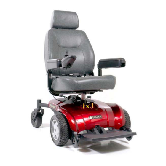
ALANTE DX/LT_SG_REVA_030112 Alante DX/LT Nomenclature 1. Seat 2. Arm Assembly 3. Seat Swivel 4. Joystick 5. Joystick Arm 6. Seat Post 7. Seat Post Nut and Bolt 8. Front Anti-Tip Wheel 9. Footplate 10. Bottom Cover 11. Motor/Brake Assembly 12. Drive Wheel 13. -
Page 5: About The Alante Dx/Lt Service Guide
LED array when it detects a fault in the system. The Alante DX/LT power chairs are designed to operate with between 18 – 24 volts (V) of direct current (DC). The Alante DX and Alante LT control systems are made up of the following components. Refer to page 3. - Page 6 ALANTE DX/LT_SG_REVA_030112 Component: Park Brake (2) Location: End of each motor. Function: Park Brake for the motor. Connections: Each park brake has a 2 pin male connector, which connects to each motor harness. Failure Signs: Power chair will not move or moves sluggishly. No audible click when the chair stops.
- Page 7 ALANTE DX/LT_SG_REVA_030112 Component: PG VR2 Power Module Location: Front of the power base. Function: Monitors the system and displays faults when something in the system is out of range. These faults are displayed as a series of flashes by the battery meter.
-
Page 8: The Vr2 Controls
ALANTE DX/LT_SG_REVA_030112 VR2 USER CONTROLS Battery Gauge On/Off Button Horn Button Maximum Speed / Profile Indicator Speed / Increase Profile Button Speed / Decrease Profile Button CONTROL PANEL (FRONT VIEW) VR2 CONTROLS On/Off Button and Battery Gauge The on/off button applies power to the control system electronics, which in turn supply power to the wheelchair’s motors. - Page 9 ALANTE DX/LT_SG_REVA_030112 To unlock the wheelchair: • Use the on/off button to switch the control system on. The maximum speed / profile indicator will be rippling up and down. • Deflect the joystick forwards until the control system beeps. • Deflect the joystick in reverse until the control system beeps.
-
Page 10: Scenario 1: Press The On/Off Button And The Led Array Does Not Light Up (Pg Vr2)
ALANTE DX/LT_SG_REVA_030112 SCENARIO 1: Press the on/off button and the LED array does not light up. Before attempting to troubleshoot the power chair, make sure all connectors are connected and seated properly. Make sure that the batteries are connected properly and fully-charged. If the batteries are not fully charged or connected properly, then voltage measurements may produce faulty readings. -
Page 11: Scenario 2: Batteries Will Not Charge (Vr2 Charging Test)
ALANTE DX/LT_SG_REVA_030112 12. Remove the battery box; open the battery box by removing the 9 screws on the underside of the battery box. Now, disconnect the 2 white circuit breaker wires from the batteries. 13. Measure Resistance across the terminals on the circuit breaker. -
Page 12: Scenario 3: Batteries Will Not Charge (Battery Box Charging Test)
ALANTE DX/LT_SG_REVA_030112 Prevent damage to the (PG VR2) power module. Be careful when touching the leads on the power module. Do not allow the meter leads to touch each other, which will cause a short. 6. Reconnect the power harness to the power module. Disconnect the bus cable from the power module. -
Page 13: Troubleshooting Guide For (Pg Vr2)
ALANTE DX/LT_SG_REVA_030112 4. Measure voltage across the battery negative (black) terminal and the battery positive (red) terminal. • Less than 18VDC – Load test and replace batteries as necessary. • Greater than 18VDC – Go to next step. • 0VDC – Go to step 9 on page 11. - Page 14 ALANTE DX/LT_SG_REVA_030112 D. If the voltage is dropping too quickly, perform a load test on the batteries using a load tester. If you do not have access to a load tester, you can load test by performing the follow steps.
-
Page 15: Step 2: Checking "Flash Codes
ALANTE DX/LT_SG_REVA_030112 Step 2: Diagnostic “Flash Codes” If a system trip occurs, you can find out what has happened by counting the number of bars on the battery gauge that are flashing. Below is a list of self-help actions. Go to the number in the list which matches the number of flashing bars to diagnose the problem. -
Page 16: Flash Code 3: Left Motor Wiring Trip
ALANTE DX/LT_SG_REVA_030112 Flash Code 3: Left Motor Wiring Trip A. Check the resistance of the left motor to determine if the fault is in the motor or the controller. Set your meter to the 20 Ohm scale. Touch the leads together to make sure the ohm meter is accurate. You should have 0 ohms at this point. If not, your meter needs to be calibrated. -
Page 17: Flash Code 6: Charger Connected
ALANTE DX/LT_SG_REVA_030112 B. Check the resistance of the M1 motor connector on the controller. Disconnect the battery from the controller. Set your meter to the 200k ohm scale. Touch the leads together to make sure the meter is accurate. You should have 0 ohms at this point. If not, your meter needs to be calibrated. -
Page 18: Flash Code 10: High Battery Voltage
ALANTE DX/LT_SG_REVA_030112 Touch the leads together to make sure the meter is accurate. You should have 0 ohms at this point. If not, your meter needs to be calibrated. Place the red and black meter leads on the two top pins of the left and right motor connectors as shown in figure 7. -
Page 19: How To Read A Trucharge Battery Gauge
ALANTE DX/LT_SG_REVA_030112 How to Read a TruCharge Battery Gauge If the battery gauge shows red, yellow and green, the batteries are charged. If the battery gauges show just red and yellow, then you should charge the batteries as soon as you can. -
Page 20: Battery Charging Methods
ALANTE DX/LT_SG_REVA_030112 Battery Charging To charge the wheelchair batteries connect the charger plug into the battery charging socket on the VR2. You will not be able to drive the wheelchair when the charger is connected. To connect the charger plug, ensure the single pin is at the bottom, as shown in the illustration below, and then insert the charger plug into the VR2. -
Page 21: Electrical Connections
ALANTE DX/LT_SG_REVA_030112 VR2 POWER MODULE CONNECTIONS VR2 50 BATTERY MOTOR 1 MOTOR 2 Brake +ve Brake -ve Brake +ve Brake -ve Motor +ve Motor -ve Motor +ve Motor -ve Right Motor Brake Circuit Brake Left Motor Breaker INHIBIT 2 ON-BOARD CHARGER ACTUATORS Note: The inhibit-2, on-board charger, and actuator connections are not being used on this power chair. -
Page 22: Battery Wiring Diagram
ALANTE DX/LT_SG_REVA_030112 BATTERY WIRING DIAGRAM BATTERY Negative Pole Positive Pole White Bottom Conduction Connector White CIRCUIT BREAKER Black Positive Pole Negative Pole BATTERY REPLACEMENT INSTRUCTIONS DRIVE WHEEL 1. Turn off power. 2. Place the power chair in drive mode. 3. Place a support under the frame so that the drive wheel is off the ground. -
Page 23: Drive Wheel
ALANTE DX/LT_SG_REVA_030112 CASTER 1. Turn off power. 2. Place the power chair in drive mode. 3. Place a support under the frame so that the caster wheel is off of the ground. 4. Remove the cap from caster arm. See figure 9. -
Page 24: Power Module
ALANTE DX/LT_SG_REVA_030112 Power Module Motor/Brake Assembly Power Module Bolts (2) Allen head bolts (3) Figure 10. Frame with motor/brake and power module. POWER MODULE 1. Turn off power. 2. Place the power chair in drive mode. 3. Disconnect the bus cable coming from the joystick. -
Page 25: Batteries
ALANTE DX/LT_SG_REVA_030112 Figure 11. Battery Box (Inside View) BATTERIES 1. Turn off power. 2. Place the power chair in drive mode. 3. Disconnect the bus cable coming from the joystick. 4. Remove the seat. 5. Remove the battery box form the power chair. -
Page 26: Appendix A - How To Use A Voltmeter
ALANTE DX/LT_SG_REVA_030112 APPENDIX A - HOW TO USE A VOLTMETER Step 1 Plug the probes into the meter. Red goes to the positive (+) and black to the negative (-). Step 2 Turn the selector dial or switch to the type of measurement you want. To measure direct current - a battery, for example - use DCV. -
Page 27: Appendix B - How To Use An Ohm Meter
ALANTE DX/LT_SG_REVA_030112 APPENDIX B - HOW TO USE AN OHM METER Ohm’s law breaks down into the basic equation: Voltage = Current x Resistance. Current is generally measured in amps, and resistance in ohms. Testing the resistance on an electrical circuit in your home or car can help you diagnose problems with that circuit. -
Page 28: Illustrated Parts Breakdown
ALANTE DX/LT_SG_REVA_030112 ILLUSTRATED PARTS BREAKDOWN MODELS GP204/GP215 ALANTE DX COMPLETE ASSEMBLY (PWG001-391-02) Item Part Number Description Qty. P3095-0013-01 Seat post upper with angled daisy P3011-0040-01 Anti-tipper 4" PU wheel P3011-0039-01 240x75 wheel unit, with PU tire P2012-0020-01 Compass Jr frame unit... - Page 29 ALANTE DX/LT_SG_REVA_030112 Item Part Number Description Qty. 3093-0023-01 Plastic cover(sheet) 3093-0020-01 Plastic battery receiver 3093-0019-01 Plastic shroud top - in Metallic Red color 3061-0002-01 Bushing, in the fork's bearing house 3051-0015-01 spring 3046-0013-01 Spacer 3046-0012-01 Spacer 3045-0009-01 Bearing 6201-ZZ 3042-0020-01...
- Page 30 EPE bag 1012-0001-01 Binder -- black color 1010-0004-01 Zip PE bag 1009-0012-01 PE bag 1009-0006-01 PE bag 1005-0029-01 Master box for Alante DX 3053-0073-01 Maximum loading sticker 3053-0068-01 "Golden" sticker 3069-0034-01 Alante DX user's manual 3053-0069-01 "Alante DX" sticker 3053-0070-01...
- Page 31 ALANTE DX/LT_SG_REVA_030112 6x2 CASTER WHEEL (P3011-0041) Item Part Number Description Qty. 3059-0001-01 200*50 wheel bushing 3045-0001-01 608ZZ bearing 3011-0016-01 6"*2" PU wheel ANTI-TIP WHEEL (P3011-0040) Item Part Number Description Qty. 3059-0009-00 M8-10L wheel bushing - raw material 3045-0001-01 608ZZ bearing 3011-0004-03 4"...
- Page 32 ALANTE DX/LT_SG_REVA_030112 SEAT SWIVEL ASSEMBLY (A3095-0011) Item Part Number Description Qty. P3095-0012-01 Seat swivel 3095-0028-01 Lever of seat swivel 3095-0021-01 Located block of seat swivel 3051-0016-01 Spring for seat swivel located block 3038-0024-01 SQ3030-1 30x30 square tube end plug 3036-0003-02...
- Page 33 ALANTE DX/LT_SG_REVA_030112 LEFT ARMREST ASSEMBLY (A3095-0010) Item Part Number Description Qty. P3095-0006-01 Long armrest bracket P2053-0006-01 CN armrest support bracket - left side P2053-0005-01 CN armrest support fixed bracket 3033-0018-01 HC-179 long arm pad - left side 0014-0002-01 Nylon washer M8.2-16 0008-0001-01 M6-P1.0 nut...
- Page 34 ALANTE DX/LT_SG_REVA_030112 RIGHT ARMREST ASSEMBLY (A3095-0009) Item Part Number Description Qty. P3095-0007-01 Short armrest bracket P2053-0007-01 CN armrest support bracket - Right side P2053-0005-01 CN armrest support fixed bracket 3033-0019-01 HC-179 arm pad - Right side 0014-0002-01 Nylon washer M8.2-16B-1t 0008-0001-01 M6-P1.0 nut...
- Page 35 ALANTE DX/LT_SG_REVA_030112 CASTER WHEEL ASSEMBLY (A3067-0040) Item Part Number Description Qty. P3011-0041-01 6x2 PU wheel unit 3008-0002-01 Front fork axle 3007-0016-01 Fork of 6x2 PU wheel unit 0012-0009-02 Iron washer M8-16B-1.5t 0009-0002-01 Nut for front fork axle 0006-0004-02 M12-P1.25 Nylock nut 0006-0003-02 M8-P1.25 Nylock nut...
- Page 36 Item Part Number Description Qty. P3026-0033-01 40A circuit breaker for Compass Jr (Alante DX) P3026-0031-01 Battery charger wire for Compass Jr (Alante DX) 3082-0007-01 WP22-12NE 22AH battery 3064-0012-01 Battery box base for Compass Jr (Alante DX) 3064-0011-01 Battery box lid for Compass Jr (Alante DX)
- Page 37 ALANTE DX/LT_SG_REVA_030112 JOYSTICK CONTROL ARM ASSEMBLY (A2029-0006) Item Part Number Description Qty. 3038-0005-01 SQ1818 18x18 square tube end plug 2029-0031-01 VR-2 controller fixed plate 2029-0030-01 Controller fixed bracket 0006-0002-02 M5-P0.8 nylon nut 0000-0005-02 Half-dome head screw with inner hexagon hole M5-30...
- Page 38 ALANTE DX/LT_SG_REVA_030112 Golden Technologies 401 Bridge Street Old Forge, PA 18518 www.goldentech.com ALANTE DX/LT_SERVMAN_REVA_030112...
Need help?
Do you have a question about the Alante DX and is the answer not in the manual?
Questions and answers