Inogen One G2 User Manual
Oxygen concentrator
Hide thumbs
Also See for One G2:
- User manual (340 pages) ,
- Technical manual (20 pages) ,
- User manual (44 pages)
Table of Contents
Advertisement
Quick Links
- 1 General Instructions
- 2 Operating Instructions
- 3 Inogen One® G2 Oxygen Concentrator Audible and Visible Signals (Including Alarms)
- 4 Troubleshooting
- 5 Cleaning, Care and Maintenance
- 6 Filter Cleaning and Replacement
- 7 Other Service and Maintenance
- 8 Symbols Used on Concentrator and Accessories
- Download this manual
See also:
User Manual
Advertisement
Table of Contents

Related Manuals for Inogen One G2


Summary of Contents for Inogen One G2
- Page 1 user manual ®...
-
Page 3: Table Of Contents
Contents Chapter 1 Intended Use, Contraindications and General Precautions Chapter 2 Description of the Inogen One® G2 Oxygen Concentrator Important Parts of the Inogen One® G2 Oxygen Concentrator User Controls User Interfaces Input / Output Connections Power Supply Options Inogen One® G2 Accessories... -
Page 5: Intended Use, Contraindications And General Precautions
One® G2 may be used in home, institution, vehicle, on an airplane and various mobile environments. The expected life for the Inogen One® G2 Oxygen System is 5 years, with the exception of the batteries, which have an expected life of 500 full charge/discharge cycles. - Page 6 Do NOT ALLOW SMOKING OR OPEN FLAMES within 10 feet of this device while in use. WARNING Do not submerse the Inogen One® G2 or any of the accessories in liquid. Do not expose to water or precipitation. Do not operate in exposed rain.
-
Page 7: Description Of The Inogen One® G2 Oxygen Concentrator
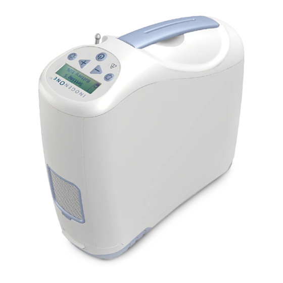
Description of the Inogen One® G2 Oxygen Concentrator Important Parts of the Inogen One® G2 Oxygen Concentrator Display Flow Control Display Audible Backlight Alarm Button Button Alert/Alarm Light Breath Detection Light On/Off Button Description of the Inogen One® G2 Oxygen Concentrator Chapter 2... -
Page 8: User Controls
Pressing this button will toggle the Inogen One® G2’s breath detection audible alert on and off: 1. Default Mode. When the Inogen One® G2 is powered up, the breath detection audible alert is disabled. The display’s mode indication area will show a bell icon crossed out with an X in default mode. -
Page 9: Input / Output Connections
The filter must be in place at the intake end of the concentrator during operation to keep input air clean. Cannula Nozzle Fitting The nasal cannula connects to this nozzle for Inogen One® G2 output of oxygenated air. DC Power In Connection for external power from the Universal Power Supply. -
Page 10: Power Supply Options
Inogen One® G2 Oxygen Concentrator (IO-200). The Universal Power Supply provides the precise current and voltage required to safely power the Inogen One® G2 and is designed to operate from specified AC and DC power sources. When used with AC power sources, the power supply automatically adapts to input voltages from 100V to 240V (50-60HZ) permitting use with most power sources throughout the world. - Page 11 Keep children and pets away from cord. Doing so may lead to damaged cords and a failure to provide power to the concentrator. * Actual product appearance may vary . Description of the Inogen One® G2 Oxygen Concentrator Chapter 2...
- Page 12 Model# BA-207 Power Output Plug Universal Power Supply AC Input DC Input LED Indicator Light AC Power Plug * DC cigarette lighter Power Plug for use in Automobile/RV/Boat/Aircraft (RP# 222) * WARNING Do not use power supplies or power cables other than those specified in this user manual.
- Page 13 Keep children and pets away from cord. Doing so may lead to damaged cords and a failure to provide power to the concentrator. * Actual product appearance may vary . Description of the Inogen One® G2 Oxygen Concentrator Chapter 2...
- Page 14 Model# BA-302 DC Power Supply Indicator Light DC cigarette lighter Power Plug for use in Automobile/RV/ Boat/Aircraft * Power Output Plug * WARNING Do not use power supplies or power cables other than those specified in this user manual. The use of non-specified power supplies or power cables may create a safety hazard and/or impair equipment performance.
-
Page 15: Inogen One® G2 Accessories
Nasal Cannula A nasal cannula must be used with the Inogen One® G2 to provide oxygen from the concentrator. A single lumen cannula up to 25 feet in length is recommended to ensure proper breath detection and oxygen delivery. - Page 16 2. Plug the External Battery Charger AC power supply into the battery charger. 3. Slide your charger onto the Inogen One® G2 Battery by clicking and locking into the charger. 4. When the battery is in the correct position, a solid red light will indicate that the battery is charging.
-
Page 17: Operating Instructions
Locate the Inogen One® G2 in such a way that any auditory Intake alarms may be heard. WARNING Avoid use of the Inogen One® G2 in presence of pollutants, smoke or fumes. Do not use the Inogen One® G2 in presence of flammable anesthetics, cleaning agents or other chemical vapors. - Page 18 CAUTION The Inogen One® G2 battery acts as a secondary power supply in the event of a planned or unexpected loss of the AC or DC external power supply. When operating the Inogen One® G2 from an AC or DC external power supply, a properly inserted Inogen One®...
- Page 19 5. Connect the nasal cannula tubing to the nozzle fitting. Nozzle fitting is located next to the handle of the Inogen One® G2. Use of a single lumen cannula up to 25 feet in length is recommended to ensure proper breath detection and oxygen delivery.
- Page 20 7. Set the Inogen One® G2 Concentrator to the flow rate prescribed by your physician or clinician. Use the + or – setting buttons to adjust the Inogen One® G2 to the desired setting. The current setting can be viewed on the display.
-
Page 21: Additional Operating Instructions
Now you get the same quality performance and convenience while on the go that you’re used to receiving from your Inogen One® G2 at home. Here are some useful and important instructions for maximizing performance and convenience when using your Inogen One®... - Page 22 Traveling By Air The FAA allows the Inogen One® G2 onboard all U.S. aircraft, here are a few points to make air travel easy. Planning Your Flight When flying with the Inogen One®...
- Page 23 • Some airlines may equip their aircraft with onboard electrical power. You may have an opportunity to request a seat with a power port which can be used to power your Inogen One® G2. However, availability varies by airline, type of aircraft and class of service. You should check with your airlines for availability and always plan on having sufficient battery power for the duration of your flight, plus a conservative estimate of unanticipated delays.
-
Page 24: Battery Operating Instructions
Your Inogen One® G2 will fit upright under most airline seats. However, if it doesn’t fit you may turn it on its side. • It is not necessary to turn off your Inogen One® G2 during taxi, takeoff and landing if your physician’s written statement requires you receive oxygen during these periods. -
Page 25: Battery Care And Maintenance
When battery life is low, do one of the following: • Plug the Inogen One® G2 into an AC or DC power source using the Universal Power Supply. • Replace the battery with a charged battery after turning off the Inogen One® G2 (by pressing the ON/OFF button). - Page 26 Battery Time Remaining Clock The Inogen One® G2 continuously displays battery time remaining. This displayed time is only an estimate and the actual time remaining may vary from this value. Please Follow These Important Guidelines to Maximize Battery Performance and Life: •...
-
Page 27: Inogen One® G2 Oxygen Concentrator Audible And Visible Signals (Including Alarms)
Power Display Icons The Inogen One® G2 display is divided into three areas. The upper left corner of the display shows the breath detection alert status. The lower left corner indicates power source and battery charge level. The right side of the display contains text information, such as flow setting, battery time remaining and error notifications. - Page 28 Power Status Icons (continued) The icons below are examples of those shown when the Inogen One® G2 is operating from an external power supply and charging the battery. The lightening bolt indicates that an external power supply is connected. Icon Meaning Battery is charging with charge level between 60% and 70%.
- Page 29 The Inogen One® G2 monitors various parameters during operation and utilizes an intelligent alarm system to indicate a malfunction of the concentrator. Mathematical algorithms and time delays are used to reduce the probability of false alarms while still ensuring proper notification of an alarm condition.
- Page 30 If multiple alarm conditions are detected, the highest priority alarm will be displayed. The following notification messages are accompanied by a single, short beep. Message Display & Text Condition/Action/Explanation Inogen One® On/Off button has been pressed for two seconds. Shutting Down Concentrator is performing system shut down.
- Page 31 10-15 minutes. Then, re-insert the battery into the Inogen One® G2. If the problem still persists, contact your equipment provider. Concentrator is producing oxygen but cannot report Comm Error battery status.
- Page 32 Medium Priority Alerts The following medium priority alert messages are accompanied by a triple beep, repeated every 25 seconds, and a flashing red light. Message Display & Text Condition/Action/Explanation Battery HOT Battery has exceeded temperature limit while concentrator Warning is running on battery power. If possible, move concentrator to a cooler location or power unit with an external power supply and remove battery.
- Page 33 High Priority Alerts CAUTION If you are not near the Inogen One® G2 you may not be able to hear or see the high priority alerts. Make sure the Inogen One® G2 is in a location where the alerts and alarms will be recognized if they occur.
- Page 34 High Priority Alerts (continued) Message Display & Text Condition/Action/Explanation System COLD This may result from the concentrator being stored in a Shut Down cold environment (below 0ºC (32ºF)). Move to a warmer environment to allow the unit to warm up before starting it.
-
Page 35: Troubleshooting
Troubleshooting Solutions to some possible issues you may encounter are described in this section. Inogen One® G2 Oxygen Concentrator Problem Possible Cause Recommended Solution Any problem Refer to Chapter 4 Refer to Chapter 4 accompanied by information on concentrator display, indicator... -
Page 37: Cleaning, Care And Maintenance
You may clean the outside case using a cloth dampened with a mild liquid detergent (such as Dawn ) and water. WARNING Do not submerse the Inogen One® G2 or its accessories in water or allow water to enter into the case; this may lead to electrical shock and/or damage. -
Page 38: Filter Cleaning And Replacement
The output filter may be replaced by the equipment provider or by the owner using the Output Filter Replacement Kit (RP-107). The Inogen One G2 Concentrator must be cleaned and disinfected as per the above instructions for each new patient. No special maintenance needs to be carried out by the patient. - Page 39 3. The spring should remain inside the Cigarette Lighter Adapter housing. If the spring is removed, make sure to replace the spring first before inserting the replacement fuse. 4. Install a replacement fuse, Inogen RP#125 (BUSS MDA-12) and reassemble the tip. Ensure the retainer ring is properly seated and tightened. Retainer...
-
Page 40: Other Service And Maintenance
Other Service and Maintenance WARNING Do not disassemble the Inogen One® G2 or any of the accessories or attempt any maintenance other than tasks described in the troubleshooting section; disassembly creates a hazard of electrical shock and will void your warranty. Do not remove the tamper evident label. For events other than those described in this manual, contact your equipment provider for servicing by authorized personnel. -
Page 41: Symbols Used On Concentrator And Accessories
Symbols Used On Concentrator and Accessories Symbol Meaning A warning indicates that the personal safety of the patient may be WARNING involved. Disregarding a warning could result in significant injury. A caution indicates that a precaution or service procedure must be followed. - Page 42 Symbol Meaning Keep Dry Indoor or Dry Location Use Only, Do Not Get Wet Use No Oil or Grease ONLY Do Not Disassemble (contact your equipment provider for servicing by authorized personnel) Do Not Dispose of In Unsorted Municipal Waste ONLY Type BF Applied Part, Not Intended for Cardiac Application Class II Device...
- Page 43 Temperature: -13 to 158˚F (-25 to 70˚C) Intended for Shipping and Humidity: 0% to 95%, non-condensing Storage: Store in a dry environment Altitude: 0 to 10,000 ft (0 to 3048 meters) Transportation: Keep Dry, Handle With Care Inogen One® G2 System Specifications Chapter 8...
- Page 44 Inogen One® G2 Concentrator (continued) Tested by Independent Safety: IEC 60601-1 Laboratory: CAN/CSA C22.2 No. 60601-1 Electromagnetic Compatibility: IEC 60601-1-2 RTCA DO 160 Classifications Mode of Operation: Continuous Duty Type of Protection Against Electrical Class II Shock: Degree of Protection to Concentrator...
- Page 45 Guidance and Manufacturer’s Declaration - Electromagnetic Immunity: The Inogen One® G2 Oxygen Concentrator is intended for use in the electromagnetic environment specified below. The user of the Inogen One® G2 Oxygen Concentrator should make sure it is used in such an environment.
- Page 46 Guidance and Manufacturer’s Declaration - Electromagnetic Immunity (continued): Immunity Test IEC 60601 Compliance Electromagnetic Test Level Level Environment - Guidance Field strengths from fixed RF transmitters, as determined by an electromagnetic site survey , should be less than the compliance level in each frequency range Interference may occur in the vicinity of equipment marked...
- Page 47 These guidelines may not apply in all situations. Electromagnetic propagation is affected by absorption and reflection from structures, objects, and people. NOTE is the a.c. mains voltage prior to application of the test level. Inogen One® G2 System Specifications Chapter 8...
- Page 48 To assess the electromagnetic environment due to fixed RF transmitters, an electromagnetic site survey should be considered. If the measured field strength in the location in which the Inogen One® G2 Oxygen Concentrator is used exceeds the applicable RF compliance level above, the Inogen One®...
- Page 49 Communications Equipment and This Device: This device is intended for use in an electromagnetic environment in which radiated RF disturbances are controlled. The customer or the user of the Inogen One® G2 Oxygen Concentrator can help prevent electromagnetic interference by maintaining a minimum distance between portable and mobile RF communications equipment (transmitters) and this Inogen One®...
- Page 50 Guidance and Manufacturer’s Declaration – Electromagnetic Emissions The Inogen One® G2 Oxygen Concentrator is intended for use in the electromagnetic environment specified below. The customer or the user of the Inogen One® G2 Oxygen Concentrator should assure that it is used in such an environment.
Need help?
Do you have a question about the One G2 and is the answer not in the manual?
Questions and answers