Table of Contents
Advertisement
Advertisement
Table of Contents

Related Manuals for TRENDnet TEG-082WS


Summary of Contents for TRENDnet TEG-082WS
-
Page 2: Table Of Contents
..........................86 NOOPING LLDP (L ) ................90 AYER ISCOVERY ROTOCOL ............................93 TATISTIC ......................... 94 WITCH AINTENANCE ......................101 ETTINGS TO LASH WEB SMART SWITCH MANAGEMENT UTILITY ..........102 ......................102 YSTEM EQUIREMENTS © Copyright 2014 TRENDnet. All Rights Reserved. -
Page 3: Product Overview
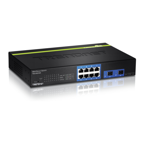
Features 802.1X, TACACS+, and RADIUS are compatible with layered network access controls TRENDnet’s fanless 8-Port Gigabit Web Smart Switch, model TEG-082WS, offers 8 x Gigabit ports, 2 x shared SFP slots, a built-in power supply, and a 16 Monitoring Gbps switching capacity. This IPv6 ready switch offers advanced traffic... -
Page 4: Front View
Ports 7 and 8 are shared with SFP slots 7F and 8F and will be disabled when SFP slots (7F, 8F) are in use. SFP slots (7F, 8F) Supports optional 100 or 1000BASE-SX/LX mini-GBIC modules. © Copyright 2014 TRENDnet. All Rights Reserved. - Page 5 10Mbps Ethernet network. Amber link is established. Blink in Traffic is passing through this SPF port with 100Mbps link. Amber No link Duplex (per port) Full duplex Ethernet Half duplex Ethernet © Copyright 2014 TRENDnet. All Rights Reserved.
-
Page 6: Rear View
Power cord (1.8 m / 6 ft.) • Rack mount hardware If any package content is missing or damaged, please contact the retail store, online retailer, or reseller/distributor from which the product was purchased. © Copyright 2014 TRENDnet. All Rights Reserved. -
Page 7: Rack Mount Hardware Installation
Basic Installation The switch can be mounted in an EIA standard-size, 19-inch rack, which can 1. Power on your TEG-082WS and connect your computer to the switch. be placed in a wiring closet with other equipment. Attach the mounting brackets at the switch’s front panel (one on each side), and secure them with the provided screws. - Page 8 7. Click Save Settings to Flash on the bottom of the menu. 8. Click button, then click OK. Note: Once the settings are saved, you can connect the switch to your network. 5. Click System and then click IPv4 Setup. © Copyright 2014 TRENDnet. All Rights Reserved.
-
Page 9: Connect Additional Devices To Your Switch
Note: If you encounter issues connecting to your network, there may be a problem with your computer or device network settings. Please ensure that your computer or device network settings (also called TCP/IP settings) are configured properly within the network subnet your switch is connected. © Copyright 2014 TRENDnet. All Rights Reserved. -
Page 10: Configure Your Switch
Access your switch management page You can view your switch status information here. Note: Your switch default management IP address http://192.168.10.200. You can manage the TEG-082WS websmart switch using Internet web browser on your choice. (e.g. Internet Explorer®, Firefox®, Chrome™, Safari®, or Opera™). - Page 11 System MAC Address, IPv4 Information MAC Address: Displays the switch system MAC address. IP Address: Displays the current IPv4 address assigned to your switch. Subnet Mask: Displays the current IPv4 subnet mask assigned to your switch. © Copyright 2014 TRENDnet. All Rights Reserved.
-
Page 12: System
30 characters. System Contact: Specifies the name of the network administrator responsible for managing the switch. This contact name is optional and may contain up to 30 characters. © Copyright 2014 TRENDnet. All Rights Reserved. - Page 13 System IP Mode: Click the drop-down list and select Static to manually specify your IP address settings or DHCP to allow your switch to obtain IP address settings automatically from a DHCP server on your network. © Copyright 2014 TRENDnet. All Rights Reserved.
- Page 14 Only one link local address is supported. If a link local address exists on the interface, this entry replaces the address in the configuration. Link Local Enter the Link Local Address/Prefix Length. Address/Prefix length: © Copyright 2014 TRENDnet. All Rights Reserved.
- Page 15 DNS IPv6 Server: Specifies the IPv6 DNS server address. Click Add to save the entry to the list. Go Save Settings to Flash section to save the change on the flash to make sure the change is permanent. © Copyright 2014 TRENDnet. All Rights Reserved.
- Page 16 Page field and click Go or you can click First, Previous, Next, and Last Page to navigate the pages. Go Save Settings to Flash section to save the change on the flash to make sure the change is permanent. © Copyright 2014 TRENDnet. All Rights Reserved.
- Page 17 Password: Enter the password for the new account Confirm Password: Enter the password again for verification. Note: The password consists of up to 12 alphanumeric characters. Click Add to add the new administrator. © Copyright 2014 TRENDnet. All Rights Reserved.
- Page 18 Enabled: The SNMP agent is active. You can manage the switch with SNMP network management software and the switch’s private MIB. Disabled: The SNMP agent is inactive. Web Server Status: Displays the current SNMP status. © Copyright 2014 TRENDnet. All Rights Reserved.
- Page 19 Group Interval: The IGMP group timeout interval. Default: 120 sec. Click Apply to apply the change to the switch Go Save Settings to Flash section to save the change on the flash to make sure the change is permanent. © Copyright 2014 TRENDnet. All Rights Reserved.
- Page 20 IPv4, IPv6 address or domain name. SNTP Secondary Select the format of the URL you want to enter for Server: SNTP server address. Enter the secondary network time server IPv4, IPv6 address or domain name. © Copyright 2014 TRENDnet. All Rights Reserved.
- Page 21 SSL Status: Enable or disable HTTPS/SSL management access or to HTTP clear text mode. Default: Disabled. Note: When SSL is enabled, you need to access the switch management page using HTTPS instead of HTTP. (e.g. https://192.168.10.200) © Copyright 2014 TRENDnet. All Rights Reserved.
- Page 22 Default: Disabled. State: Click Apply to apply the change to the switch Go Save Settings to Flash section to save the change on the flash to make sure the change is permanent. © Copyright 2014 TRENDnet. All Rights Reserved.
-
Page 23: Physical Interface
7. Debug: Debug-level messages are displayed. Click Apply to apply the change to the switch Go Save Settings to Flash section to save the change on the flash to make sure the change is permanent. © Copyright 2014 TRENDnet. All Rights Reserved. - Page 24 100/Full -This parameter indicates the port is All Ports: configured for 100Mbps operation in full-duplex If you select Ignore and click on Apply for all ports, the mode. Admin Status is not changing. If you select Enabled then © Copyright 2014 TRENDnet. All Rights Reserved.
- Page 25 Disabled: This port is disabled and not doing flow jumbo frames when your switch will transmit video and control. audio files. Note: Click Apply in the end of the row to apply the change. © Copyright 2014 TRENDnet. All Rights Reserved.
- Page 26 Disabled: This port is disabled and the switch will not pass BPDU frames through the switch. With RSTP or STP enabled, the switch will receive BPDU frames and process them according to the spanning tree protocol. © Copyright 2014 TRENDnet. All Rights Reserved.
-
Page 27: Bridge
• STP: Enables STP 802.1D on the device. • RSTP: Enables Rapid STP 802.1w on the device. This is the default value. • MSTP: Enables Multiple STP 802.1s on the device. • © Copyright 2014 TRENDnet. All Rights Reserved. - Page 28 Click Apply to apply the change to the switch the port. Enable Disable Go Save Settings to Flash section to save the change on the flash to make sure the change is permanent. © Copyright 2014 TRENDnet. All Rights Reserved.
- Page 29 BPDU data. A port with a higher path cost to the root © Copyright 2014 TRENDnet. All Rights Reserved.
- Page 30 BPDU that a bridge sends out to its root port to signal a topology change. If set to True, it stops the port from propagating received TCN and to other ports. The default value is False. © Copyright 2014 TRENDnet. All Rights Reserved.
- Page 31 Revision Level: This value, together with the configuration name, and identical VLAN mapped for STP instance IDs identifies the MST region configured on the switch. Range: 0 to 65535. Click Apply to apply the change to the switch © Copyright 2014 TRENDnet. All Rights Reserved.
- Page 32 Instance Priority: Priority of the instance. State: STP port fording state Role: The port role in the STP: root port, designated port, backup port, or disabled port. Action: Click Apply to apply the change to the MST port © Copyright 2014 TRENDnet. All Rights Reserved.
- Page 33 Connecting the cables prior to configuring the ports can create loops in your network topology. Loops can result in broadcast storms which can severely limited the effective bandwidth of your network. © Copyright 2014 TRENDnet. All Rights Reserved.
- Page 34 System Priority: Pre assigned setting that cannot be modified. This value applies to the switch. System ID: MAC address value assigned to the individual switch. This value cannot be modified. Group: The trunk group (link aggregation group) ID number and status. © Copyright 2014 TRENDnet. All Rights Reserved.
- Page 35 Priority: To assign a port higher priority within a trunk group, find the port number and in the priority column, enter a priority value between 0 and 65535 (65535 represents the highest priority). © Copyright 2014 TRENDnet. All Rights Reserved.
- Page 36 Status: Click the drop-down menu and select one of the following options: Enabled: This parameter activates the Port Mirroring feature and the rest of the configuration parameters become active on the page. © Copyright 2014 TRENDnet. All Rights Reserved.
- Page 37 Disabled: This selection disables the Loopback Detection feature on the selected port. Note: In the All row when you select Enable or Disable instead of Ignore, the selection applies to all of the Switch ports. © Copyright 2014 TRENDnet. All Rights Reserved.
- Page 38 VLAN, VLAN ID 1. MAC Address: Enter the MAC address of the device to add. Port Member Settings Port Member: Select the port where the MAC address will reside. Note: Click Apply to apply the change. © Copyright 2014 TRENDnet. All Rights Reserved.
- Page 39 VLAN (VLAN 1). MAC Address: Enter the MAC address of the device to add. Group Member Settings Group Member: Select the port where the MAC address will reside. Note: Click Apply to apply the change. © Copyright 2014 TRENDnet. All Rights Reserved.
- Page 40 Age-Out Timer: Enter the amount of time in seconds that you want your switch to wait before it purges an inactive dynamic MAC address. Querier Status: Click the drop-down list and select Enabled to enable the Querier Status or Disabled to disable this feature. © Copyright 2014 TRENDnet. All Rights Reserved.
- Page 41 Router ports. IGMP Snooping Router Port configured manually is a Static Router Port, and a Dynamic Router Port is dynamically configured by the Switch when a query control message is received. To modify an entry, click Modify to add statically add router ports. © Copyright 2014 TRENDnet. All Rights Reserved.
- Page 42 Port: The port ID you want to implement the storm control. DLF: Destination Lookup Failure: Click the drop-down list and select Enabled to enable DLF storm control. Broadcast: Click the drop-down list and select Enabled to enable broadcast storm control. © Copyright 2014 TRENDnet. All Rights Reserved.
- Page 43 Action: Modifying settings in the row marked All, will apply the settings to all ports. Click Apply to apply the change. Go Save Settings to Flash section to save the change on the flash to make sure the change is permanent. © Copyright 2014 TRENDnet. All Rights Reserved.
- Page 44 Action: Modifying settings in the row marked All, will apply the settings to all ports. Click Apply to apply the change. Go Save Settings to Flash section to save the change on the flash to make sure the change is permanent. © Copyright 2014 TRENDnet. All Rights Reserved.
- Page 45 VLAN, typically tagged VLAN ports are used for uplink and downlink to other switches to carry and forward traffic for multiple VLANs across multiple switches. Tagged VLAN © Copyright 2014 TRENDnet. All Rights Reserved.
- Page 46 Click the drop-down list and select which type of Frame Type: frames can be accepted: All: The port can accept all frame types. Tagged: The port can accept tagged frames only. Untagged frames are discarded. © Copyright 2014 TRENDnet. All Rights Reserved.
- Page 47 Go Save Settings to Flash section to save the change on the flash to make When using SVL mode, the VID field on 802.1Q-VLAN mode will be sure the change is permanent. displayed as "N/A". © Copyright 2014 TRENDnet. All Rights Reserved.
- Page 48 If the entries span multiple pages, you can navigate page number in the Page field and click Go or you can click First, Previous, Next, and Last Page to navigate the pages. © Copyright 2014 TRENDnet. All Rights Reserved.
- Page 49 Press Apply to make the changes to take effect. Set the Source Port to on port 1 – 8. Click on the Forwarding Ports ratio button that applies to your configuration. Click Apply. © Copyright 2014 TRENDnet. All Rights Reserved.
- Page 50 Click the GVRP Status drop-down list and select Enabled to activate GVRP or Disabled to deactivate GVRP. Click Apply to save the settings. Go Save Settings to Flash section to save the change on the flash to make sure the change is permanent. © Copyright 2014 TRENDnet. All Rights Reserved.
- Page 51 Ignore: This parameter indicates that the setting in the All row does not apply to the Dynamic Vlan Status field. In other words, each port is set individually. © Copyright 2014 TRENDnet. All Rights Reserved.
- Page 52 10, the value is rimmed down to the multiple of 10. GVRP Time Settings Port: The port number on the switch. JoinTime: This parameter is the GARP Join Timer. Its range is 10 - 1073741810 milli-seconds. © Copyright 2014 TRENDnet. All Rights Reserved.
- Page 53 Note: Before mapping the CoS priorities and the egress queues, you must disable the sure the change is permanent. Jumbo frame parameter on each port. When Jumbo frames are enabled, COS cannot be enabled. © Copyright 2014 TRENDnet. All Rights Reserved.
- Page 54 For each port whose priority you want to change, select a priority (0-7) in the User Priority column. Click Apply to save the settings. Go Save Settings to Flash section to save the change on the flash to make sure the change is permanent. © Copyright 2014 TRENDnet. All Rights Reserved.
- Page 55 Go Save Settings to Flash section to save the change on the flash to make sure the change is permanent. © Copyright 2014 TRENDnet. All Rights Reserved.
- Page 56 Specify the value of IPv6 class. Range: 0 – 255. Class: Class ID: Defines the priority assigned to the port. The priorities are Highest, High, Medium and Low. Click Add to add the traffic class setting entry to the table. © Copyright 2014 TRENDnet. All Rights Reserved.
-
Page 57: Snmp
Reset to Default: Use the device-generated Engine ID (Reset to Default will override any entry in the Engine ID field). Go Save Settings to Flash section to save the change on the flash to make sure the change is permanent. © Copyright 2014 TRENDnet. All Rights Reserved. - Page 58 To creating SNMP View Table Entries: Enter the View Name. This value must be pre-defined on the SNMP User/Group page. Enter the Subtree OID. Enter “1” for the OID Mask. © Copyright 2014 TRENDnet. All Rights Reserved.
- Page 59 Auth-Protocol has a password assigned and the Priv-Protocol has been selected as none on the SNMP User/Group page. o AuthPriv: When the Auth-Protocol or Priv-Protocol have been enabled, choose this selection. Click the Add button. © Copyright 2014 TRENDnet. All Rights Reserved.
- Page 60 Note: The views corresponding to the ReadOnly and ReadWrite Group Names are default values and cannot be removed. Go Save Settings to Flash section to save the change on the flash to make sure the change is permanent. © Copyright 2014 TRENDnet. All Rights Reserved.
- Page 61 None: Specifies no encryption is applied to SNMP data. Click Add. The new User Name and Group Name are displayed on the SNMP User/Group page. © Copyright 2014 TRENDnet. All Rights Reserved.
- Page 62 The deleted Community Name is no longer displayed in the Community table. No confirmation message is displayed. Go Save Settings to Flash section to save the change on the flash to make sure the change is permanent. © Copyright 2014 TRENDnet. All Rights Reserved.
- Page 63 If you need to modify an SNMP Trap entry, you must first delete the entry by using the procedure below and then re-enter it with the modification by creating a new SNMP trap. © Copyright 2014 TRENDnet. All Rights Reserved.
-
Page 64: Access Control Config
You can also manage sure the change is permanent. the switching priority of Ethernet packets. All of this is done by specifying policies that define the filtering and priority behavior. © Copyright 2014 TRENDnet. All Rights Reserved. - Page 65 1 being the o Destination IP MAC Mask Length: Specifies the mask length highest priority. of the destination IP address ranging from 0 to 32. © Copyright 2014 TRENDnet. All Rights Reserved.
- Page 66 Replaced-DSCP: Enter a number in the Replaced-DSCP field within the range of 0 to 63. This field indicates the DSCP level of interest. This field is not mandatory and you may elect to leave it blank. © Copyright 2014 TRENDnet. All Rights Reserved.
- Page 67 On the list, you can click Modify to modify an entry or click Delete or delete menu to select one of the following parameters: the entry. You can also click Delete All to delete all of the entries in the table. © Copyright 2014 TRENDnet. All Rights Reserved.
- Page 68 1–65535 which identifies the policy. This field is mandatory. Enter a number in the Committed Rate column ranging from 1 to 15625. Click Add to add the rate control settings to the Rate Control Table. © Copyright 2014 TRENDnet. All Rights Reserved.
- Page 69 Then select the order to sort Index or Sequence. Note: The Any option will display policies for all ports. View the active policies associated with the specified port. © Copyright 2014 TRENDnet. All Rights Reserved.
-
Page 70: Rmon
Click the RMON Status drop-down list and select Enabled to enable RMON. the RMON feature to be active. Click Apply to save settings. Go Save Settings to Flash section to save the change on the flash to make sure the change is permanent. © Copyright 2014 TRENDnet. All Rights Reserved. - Page 71 Owner: This parameter is used to identify the person who created an entry. It is primarily intended for switches that are managed by more than one person, and is an optional field. © Copyright 2014 TRENDnet. All Rights Reserved.
- Page 72 Go or you can click First, Previous, Next, and Last Page to navigate the pages. Go Save Settings to Flash section to save the change on the flash to make sure the change is permanent. © Copyright 2014 TRENDnet. All Rights Reserved.
- Page 73 The choices are to log a message in the event log of the Switch, send an SNMP trap to an SNMP workstation, or both. Since there are only three possible actions and since events can be used © Copyright 2014 TRENDnet. All Rights Reserved.
- Page 74 This parameter specifies the event index for the falling Index: threshold. Its range is 1 to 65535. This field is mandatory and must match an Event Index that you previously entered in “Events”. © Copyright 2014 TRENDnet. All Rights Reserved.
- Page 75 Go or you can click First, Previous, Next, and Last Page to navigate the pages. Go Save Settings to Flash section to save the change on the flash to make sure the change is permanent. © Copyright 2014 TRENDnet. All Rights Reserved.
-
Page 76: Voice Vlan
“Not Member” ports. The “Not Member” ports are three complete bytes of its MAC address. eligible to dynamically join the voice VLAN when voice data is detected with © Copyright 2014 TRENDnet. All Rights Reserved. - Page 77 VLAN ID that matches your voice VLAN ID. Each of the voice VLAN ports connected to an IP phone should be configured as “Not Member” ports of the tagged VLAN. © Copyright 2014 TRENDnet. All Rights Reserved.
- Page 78 QoS must be Enabled. • Click Apply to apply the settings. • In the table at the bottom of the page, the Voice VLAN Auto- Detection status is defined. From the Auto-Detection column, select © Copyright 2014 TRENDnet. All Rights Reserved.
- Page 79 Note: If you find more than one OUI among the IP phones you are installing, enter one MAC address that represents each individual OUI. You can enter a total of 10 OUIs. © Copyright 2014 TRENDnet. All Rights Reserved.
-
Page 80: Security
Based on these entries, the authentication process is done locally by the Web Management Utility using a standard EAPOL transaction. Note: RADIUS with Extensible Authentication Protocol (EAP) extensions is the only supported authentication server for this feature. © Copyright 2014 TRENDnet. All Rights Reserved. - Page 81 Port Access Control: This parameter enables or disables Port Access Control. Select one of the following choices from the pull down menu: o Enable: The Port Access Control feature is activated. o Disable: The Port Access Control feature is de-activated. © Copyright 2014 TRENDnet. All Rights Reserved.
- Page 82 Go or you can click First, Previous, Next, and Last Page to navigate the pages. Go Save Settings to Flash section to save the change on the flash to make sure the change is permanent. © Copyright 2014 TRENDnet. All Rights Reserved.
- Page 83 Accounting Port: Set the RADIUS account server(s) UDP port. The default port is 1813. Range: 1 – 65535. Shared Secret: Enter the default authentication and encryption key for RADIUS communication between the device and the RADIUS server. © Copyright 2014 TRENDnet. All Rights Reserved.
- Page 84 In the list, you can click Modify to modify an entry or click Delete or delete the entry. Go Save Settings to Flash section to save the change on the flash to make sure the change is permanent. TACACS+ Settings © Copyright 2014 TRENDnet. All Rights Reserved.
-
Page 85: Destination Mac Filter
The Destination MAC Filter is a subset of the static MAC address. Go Save Settings to Flash section to save the change on the flash to make sure the change is permanent. © Copyright 2014 TRENDnet. All Rights Reserved. - Page 86 MAC SA Mismatch is set to Deny, it may cause devices in load balance configuration using shared virtual IP addresses communication issues essential for network server load balancing.) For additional security, you can set these rules to Deny as necessary. © Copyright 2014 TRENDnet. All Rights Reserved.
-
Page 87: Dhcp Snooping
Select one of the following choices from the pull-down Option 82: menu: Enabled: Allows an Option 82 packet to be passed through the switch without being altered. Disabled: Blocks an Option 82 packet from passing through the switch. © Copyright 2014 TRENDnet. All Rights Reserved. - Page 88 Go Save Settings to Flash section to save the change on the flash to make Go Save Settings to Flash section to save the change on the flash to make sure the change is permanent. sure the change is permanent. © Copyright 2014 TRENDnet. All Rights Reserved.
- Page 89 Next to each port, click the Trust drop-down list and select one of the following options. • Disabled: This parameter defines the port as untrusted for the DHCP Snooping feature. • Enabled: This parameter defines the port as trusted for the DHCP Snooping feature. © Copyright 2014 TRENDnet. All Rights Reserved.
- Page 90 Go Save Settings to Flash section to save the change on the flash to make VLAN: Enter the host’s VLAN ID. sure the change is permanent. Port: Enter the port number where the host is connected. © Copyright 2014 TRENDnet. All Rights Reserved.
-
Page 91: Lldp (Link-Layer Discovery Protocol)
Link Layer Discovery Protocol (LLDP) allows Ethernet network devices, such as switches and routers, to receive and transmit device-related information to directly connected devices on the network and to store data that is learned about other devices. © Copyright 2014 TRENDnet. All Rights Reserved. - Page 92 Chassis ID: This parameter lists the MAC Address of the switch. You cannot change this parameter. System Name: This parameter lists the System Name of the switch. You can assign the system name. © Copyright 2014 TRENDnet. All Rights Reserved.
- Page 93 Chassis ID: This parameter is the neighboring device’s chassis ID. Port ID Subtype: This parameter describes the Port ID subtype of the neighboring network device’s port that is connected directly to the switch port. © Copyright 2014 TRENDnet. All Rights Reserved.
-
Page 94: Statistic
OutUcastPkts: Outbound Unicast Packets (Pkts), number of outbound unicast packets in packets per second. OutNUcastPkts: Outbound Non-unicast Packets (Pkts), number of outbound non-unicast (such as broadcast and multicast packets) packets. OutDiscards: Outbound Discards (Pkts), number of outbound discarded packets. © Copyright 2014 TRENDnet. All Rights Reserved. -
Page 95: Switch Maintenance
Tools > Firmware Upgrade TRENDnet may periodically release firmware upgrades that may add features or fix problems associated with your TRENDnet switch model and version. To check if there is a firmware upgrade available for your device, please check your... - Page 96 Browse or Choose File. 2. Navigate to the folder on your computer where the unzipped firmware file (.hex) is located and select it. 3. Click Apply. If prompted, click Yes or OK. © Copyright 2014 TRENDnet. All Rights Reserved.
- Page 97 Note: If prompted, choose the location on your local hard drive. If you are not prompted, the configuration file (config.bin) will be saved to your default downloads folder. Click Apply to start the firmware upgrade. © Copyright 2014 TRENDnet. All Rights Reserved.
- Page 98 TFTP Server IP: Enter the IP address of your TFTP server. Config File Name: Enter the configuration file name for the backup. (Default: config.bin) 3. Wait for the switch to restore settings. © Copyright 2014 TRENDnet. All Rights Reserved.
- Page 99 2. The deviation of “Cable Fault Distance” is +/- 2 meters. No cable may be displayed in the table when the cable is less than 2 meters in length. © Copyright 2014 TRENDnet. All Rights Reserved.
- Page 100 Go Save Settings to Flash section to save the change on the flash to make after a reboot. sure the change is permanent. © Copyright 2014 TRENDnet. All Rights Reserved.
- Page 101 Default Except IP. If you select Factory Default Except IP, all the configurations will be set to the factory defaults, but the switch management IP remains the same. Default Settings Management IP: 192.168.10.200 Admin user name: admin Password: admin © Copyright 2014 TRENDnet. All Rights Reserved.
-
Page 102: Save Settings To Flash
Click Start to start the network connectivity ping test. After the ping test, click Show Ping Results to check the ping test result. Click Save Settings to Flash button to save the change on the flash to make sure the change is permanent. © Copyright 2014 TRENDnet. All Rights Reserved. -
Page 103: Web Smart Switch Management Utility
4. At the Utility installation window, click Next. The TRENDnet Management Utility allows you to do the following: You can easily discover all TRENDnet web smart switches on your network using the discover feature. You can modify the IP address settings, change the admin password, and upgrade firmware for multiple switches. -
Page 104: Using The Utility
You can also launch the utility from the Start Menu programs. 7. In the Completion window, click Finish. Start > Programs (or All Programs) > TRENDnet Management Utility > TRENDnet Management Utility.exe © Copyright 2014 TRENDnet. All Rights Reserved. -
Page 105: Discovery List
Click on the Discovery button, you can list all the Web Smart Management switches in the discovery list. Double click or click on the Add to monitor list button to select a device from the Discovery List to the Monitor List. © Copyright 2014 TRENDnet. All Rights Reserved. -
Page 106: Device Setting
When the device has a new function, there will be a new firmware to update to change, you must enter the password and then click on Set to switch the device, use this function to update. configuration. The default password of TRENDnet Web Smart Switches is admin. © Copyright 2014 TRENDnet. All Rights Reserved. -
Page 107: Main Menu Options
View Log: To show the event of the Web Management Utility and the device. form DHCP server. (Only applies if Web Smart switch IP address settings are Clear Log: To clear the log. set to DHCP). © Copyright 2014 TRENDnet. All Rights Reserved. - Page 108 Group Interval: This is IGMP group interval. The range is from 120 to 1225 seconds. In the Help tab, you can find the utility information with About action, it will show out the version of the Web Management Utility. © Copyright 2014 TRENDnet. All Rights Reserved.
-
Page 109: Technical Specifications
Static Unicast MAC Address Table: Enable/disable 802.3az Power Saving Switch Up to 16Gbps LLDP Fabric/Capacity: Virtual Cable Test Forwarding Rate: 11.9 M pps (64-byte packet size) LED Display: • PWR (Power): Green © Copyright 2014 TRENDnet. All Rights Reserved. - Page 110 VLAN: Multiple management VLAN assignment Asymmetric VLAN 802.1Q Tagged VLAN Dynamic GVRP Up to 256 groups, ID Range 1-4094 Private VLAN (Protected Ports) Voice VLAN (10 user defined OUIs) © Copyright 2014 TRENDnet. All Rights Reserved.
-
Page 111: Troubleshooting
I changed the IP address of the switch, but I forgot it. How do I reset my switch? no other network devices assigned an IP address of 192.168.10.200 Using the TRENDnet Samrt Switch Management Utility to find your smart switch. Or, you can reset your smart switch to factory default. -
Page 112: Appendix
3. In the command prompt, enter ifconfig to display all network interface status on your MAC. 2. Select the network card you want to configure on the left banner and the network adapter status is showing here. © Copyright 2014 TRENDnet. All Rights Reserved. - Page 113 1. Open the Charms bar by moving the mouse to the top right corner of the screen or press the Windows Key + C and click on Search. 2. Type “network” in the search box and click Settings to focus your search. © Copyright 2014 TRENDnet. All Rights Reserved.
- Page 114 3. Choose Network and Sharing Center 6. Select Internet Protocol Version 4 (TCP/IPv4) and then click Properties. 4. Click Change adapter settings on the left-hand side. 5. Click Properties on the selected network adapter. © Copyright 2014 TRENDnet. All Rights Reserved.
- Page 115 1. Click Control Panel from the Start menu. Leave the other fields blank. Click OK to apply the changes. 2. Type “network” in the search box to focus your selection. Click on Network and Sharing Center © Copyright 2014 TRENDnet. All Rights Reserved.
- Page 116 TRENDnet User’s Guide TEG-082WS 3. Click Change adapter settings on the left-hand side. 5. Select Internet Protocol Version 4 (TCP/IPv4) and then click Properties 4. Click Properties on the selected network adapter. © Copyright 2014 TRENDnet. All Rights Reserved.
- Page 117 3. Click the Apple logo in the top-left corner of your screen. Click on 192.168.10.10 as the IP address, 255.255.255.0 as the Subnet mask. System Preferences..In the Internet and Wireless section, click on Leave other fields blank. Click OK to apply the changes. Network. © Copyright 2014 TRENDnet. All Rights Reserved.
- Page 118 IP address. (In order to setup the TEW-737HRE, you can put in 192.168.10.10 as the IP address, 255.255.255.0 as the subnet mask and leave router in blank. Click OK to exit advanced setup. © Copyright 2014 TRENDnet. All Rights Reserved.
-
Page 119: How To Find Your Mac Address
1. Click the Apple logo in the top-left corner of your screen. Click on System Preferences..In the Internet and Wireless section, click on Network. 3. Click Hardware to find out the MAC address of the network adapter. © Copyright 2014 TRENDnet. All Rights Reserved. -
Page 120: Regulations
This device complies with Part 15 of the FCC Rules. Operation is subject to the following two conditions: (1) This device may not cause harmful interference, and (2) this device must accept any interference received, including interference that may cause undesired operation. © Copyright 2014 TRENDnet. All Rights Reserved. -
Page 121: Europe - Eu Declaration Of Conformity
Dirrettiva 2004/108/KE u 2006/95/KE. Magyar Alulírott, TRENDnet nyilatkozom, hogy a TEG-082WS megfelel a Česky TRENDnet tímto prohlašuje, že tento TEG-082WS je ve shodě se [Hungarian] vonatkozó alapvetõ követelményeknek és az 2004/108/EK és a [Czech] základními požadavky a dalšími příslušnými ustanoveními směrnice 2006/95/EK irányelv egyéb elõírásainak. -
Page 122: Limited Warranty
RMA service must have the RMA number marked on the outside of return packages and look for the desired TRENDnet product to access to the GPL Code or LGPL Code. and sent to TRENDnet prepaid, insured and packaged appropriately for safe shipment.
Need help?
Do you have a question about the TEG-082WS and is the answer not in the manual?
Questions and answers