
Related Manuals for Main MULTIPOINT FF


Summary of Contents for Main MULTIPOINT FF
- Page 1 Please leave these instructions with the user MULTIPOINT FF Room Sealed Fan-Assisted Water Heater User Operating, Installation and Servicing Instructions...
- Page 2 Protective equipement (e.g. gloves) should be warn as necessary. User information Your Main Multipoint FF is designed to meet all relevant standards. Main provide a 12 month guarantee on the appliance. The guarantee operates from the date installation is completed for the customer who is the original owner.
-
Page 3: Table Of Contents
Contents Section page User’s operating instructions ........4 General layout ............... 5 Technical Data ............... 6 Dimensions and fixings ..........7 General inormation ............8 Installation Regulations ..........8 Siting the Appliance ............. 9 Siting the Flue Terminal ..........10 Air supply ............... -
Page 4: Switching On And Off
1. User’s Operating Instructions Switching on and off: 1. Turn the main switch to position I. 1. Turn the main switch to position 0. Water temperature control: 1. Turn the control to the desired temperature. The hot water temperature is set by the control position. -
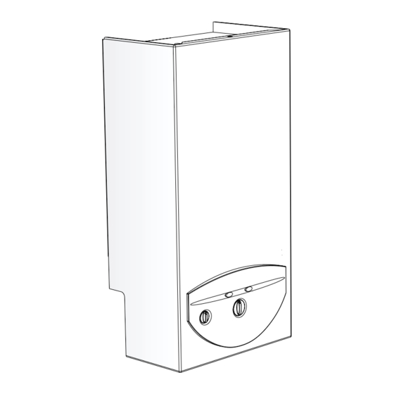
Page 5: General Layout
2. General Layout Appliance components 4 Electronic control box 5 Heat sensor 6 Water flow sensor 10 Main switch 11 Temperature control 12 Reset button 13 Burner Indicator Button 17 Safety solenoid EV1 25 Water filter 28 Hot water pipe... -
Page 6: Technical Data
3. Technical Data TABLE 1 - GENERAL Natural Gas Gas category Appliance Type Minimum rated output 10 kW Maximum rated output 23.8 kW Rated input (Net) 27 kW Gas rate (CV 34 MJ/m 2.9 m Inlet pressure 20 mbar Number of injectors Injector diameter 1.20 mm Injector marking... -
Page 7: Dimensions And Fixings
4. Dimensions and Fixings Fig. 5 6 720 607 160... -
Page 8: General Inormation
5. General Information 6. Installation Regulations GENERAL INSTALLATION Warning - Check the information on the data plate is If the appliance is to be fitted into a compartment, the compatible with local conditions. compartment must conform to the requiremens of BS 6798. Do not place anything on top of the appliance. -
Page 9: Siting The Appliance
7. Siting the Appliance 7. 1 The appliance is NOT suitable for external installation. The appliance is NOT suitable for SE DU CT application. The appliance does not require any special wall protection. The wall must be capable of supporting the weight of the appliance. -
Page 10: Siting The Flue Terminal
8. Siting the Flue Terminal See Fig. 7. The flue must be installed as specified in BS 5440:Part 1. The terminal must not cause an obstruction nor the discharge cause a nuisance. If the terminal is fitted within 1000 mm of a plastic or painted gutter or within 500 mm of painted eaves then an aluminium shield at least 1000 mm long should be fitted to the underside of the gutter or painted surface. -
Page 11: Air Supply
9. Air Supply The appliance does not require a separate vent for combustion air. The appliance may be installed in an unvented compartment. There must be sufficient clearance around the appliance to allow proper circulation of air. The clearances required for operation will normally be adequate. Refer to BS 6798 and BS5440:2 for additional information. - Page 12 5 Temperature sensor 6 Water flow sensor 7 Fuse1,25A 8 Fuse 2A 92 Gas valve 117 Ignition electrode 118 Sensing electrode 119 Temperature limit stat 226 Fan 228 Pressure switch Fig. 8 6 720 607 160...
-
Page 13: Electrical
11. Electrical See Fig. 8. 11.1 MAINS SUPPLY. 230 V ~, 50 Hz, 65 watts. 11.2 It must be possible to completely isolate the appliance. 11.3 The following connection alternatives must be used: A 3 amp fused three-pin plug and unswitched shuttered socket outlet (both complying with the requirements of BS 1363) or a double pole isolator with a contact separation of 3mm in all poles and supplying the appliance and controls... - Page 14 12.2 FLUE RESTRICTION The Installation notes in these Instructions, particularly those regarding Maximum Flue Lengths and Configuration Options, take precedence over any universal instructions included in flue component packs. To ensure the correct operation of the appliance, certain flue lengths require one of two flue restrictor rings to be fitted to the fan inlet.
- Page 15 Horizontal configuration Flue length Restrictor Configuration White flue elbow only – 4.0 m Max Table 9 no additional bends Configuration White Flue Elbow + None 2.2 m Max 1 x 90 degree bend required Configuration White Flue Elbow + None 2.5 m Max 2x 45 degree bends required...
- Page 16 12.4 FITTING A VERTICAL FLUE Possible configurations of flue are as per Fig. 17. Vertical flue kits and flue extension components are detailed in Section 3, Page 6, Table 2 - Flue Details. For vertical application the white painted elbow is discarded. The Maximum and Minimum flue lengths available for vertical configurations are as per table 12.
- Page 17 12.4.2 Extended Vertical Installation Example Example Vertical flue lengths may be extended to the limits as stated of flue of flue Flashing kit measurement measurement in Table 12 using standard 1m extension kits and 45 and with two with one flue flue 90 degree elbows.
-
Page 18: Commissioning
2 Minimum gas flow ajustment screw 3 Maximum gas flow adjuster With the main switch in position O (off), on the control 4 Gas supply pressure measuring point box front turn the temperature control to position 60. -
Page 19: Performance Optimization
14.5) Operate the appliance for approximately 5 minutes. 14.6) Set the main switch to position O (off). Fig. 23 Close the hot water tap and set the main switch back to position I (on). The performance optimisation operation is complete. -
Page 20: Inspection And Servicing
Re-assembling the Appliance Re-assemble the appliance in reverse order ensuring the following: The washer in the main gas line union is correctly located. The seals around the ignition leads and cable entries are correctly seated in the combustion chamber base. - Page 21 ‘60’ and position ‘55’ and observing the pressures. Set the main switch to position O (off), close the hot water tap and set the main switch to position I (on). The setting of maximum and minimum gas rates is now complete.
-
Page 22: Replacement Of Parts
Any servicing or parts replacement must be carried out by a competent person. Use only genuine Manufacturer’s Parts. Before commencing servicing or parts replacement turn off the gas supply at the main gas isolation valve and ensure that the appliance is cool. 16. 1... - Page 23 as per Section 15.5. 1 . 16.6 Control Unit Unfasten the two screws securing the front panel of the control unit and remove. Disconnect inlet cable and all wiring connections. Remove control unit by depressing the two curved finger tabs on top of the box and withdraw forward.
-
Page 24: Fault Finding
17. Fault Finding Note: Installation, maintenance and repairs must be carried out only by a competent person. 6 720 607 160... -
Page 25: Short Parts List
18. Short Parts List Baxi Potterton Item Number Spark Electrode 5111115 Sensing Electrode 5111116 Flow Sensor 5111117 Control Unit 5111118 Fuse T 1.25A 5111119 Fuse 2A 5111120 Pressure Switch 5111121 5111122 Gas Valve 5111123 6 720 607 160... -
Page 26: Notes
19. Notes 6 720 607 160... - Page 27 6 720 607 160...
- Page 28 GENERAL ENQUIRIES (GB) 08706 060 780 TECHNICAL (GB) 08706 049 049 SERVICE (GB) 08706 096 096 LITERATURE REQUEST (GB) 08706 060 623 TECHNICAL (IE) 1850 560 570 Baxi Potterton A Trading Division of Baxi Heating U.K. Ltd Brownedge Road Bamber Bridge Preston Lancashire PR5 6SN www.baxipotterton.co.uk Comp N 5111037 –...
Need help?
Do you have a question about the MULTIPOINT FF and is the answer not in the manual?
Questions and answers
Main multipoint ff Water heater is dripping on the left hand side. However when turned on this stops.
A Main MULTIPOINT FF water heater dripping on the left-hand side when it is off could be caused by a leak from internal components such as the heat exchanger, pipe connections, or the water sensor (turbine). Possible causes include:
1. A leaking heat exchanger due to corrosion or damage.
2. Loose or damaged inlet or outlet pipe connections.
3. A faulty or leaking water sensor or associated pipework.
4. Residual water remaining in the system after shutdown draining through a compromised seal or joint.
Inspection of these components and connections is needed to identify the exact source of the leak.
This answer is automatically generated