Table of Contents
Advertisement
User, Installation & Service
Instructions
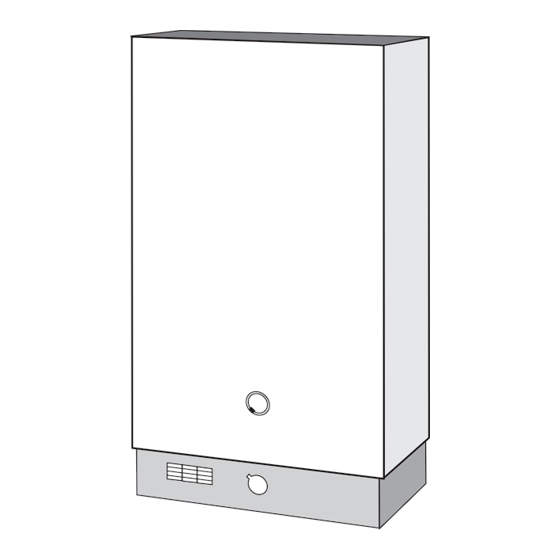
About the Heater
See inside cover for models covered by these instructions.
This is a non spouted, gas fired, multipoint water heater.
For use with Natural Gas (G20) Only at 20 mbar and for use in GB/IE Only.
About Safety
The Gas Safety (Installation and Use) Regulations.
'' In your own interest, and that of safety, it is law that all gas appliances are installed by
competent persons, in accordance with the above regulations. Failure to install appliances
correctly could lead to prosecution.''
Installation must be in accordance with the User, Installation & Servicing Instructions and the
rules in force.
Polythene bags used for packaging are a potential hazard to babies and young children and
MUST BE CAREFULLY DISPOSED OF IMMEDIATELY.
Leave these instructions with the user for use on future calls.
Supplied By www.heating spares.co Tel. 0161 620 6677
Multipoint
Water Heater
Advertisement
Chapters
Table of Contents


Need help?
Do you have a question about the Mersey Super and is the answer not in the manual?
Questions and answers
My main mersy super water heater,have had thermostat replaced,boiler now fires up but only stay on for about 20 sec.before the gas shuts off.So the pilot has to be relit.