Table of Contents
Advertisement
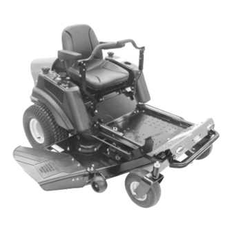
ZT
Owner/Operator Manual
Models
915074 - ZT1640
915076 - ZT1840
915078 - ZT2044
915080 - ZT2348
915082 - ZT2552
Transfer
model &
serial number
label from
Transferir aquí la etiqueta del
product reg-
istration here.
Coller l'autocollant du
modèle et du numéro de
série dans cet encadré.
modelo y número de serie
del registro del producto.
ENGLISH
FRANÇAIS
ESPAÑOL
00466700 11/05
Printed in USA
Advertisement
Table of Contents


Need help?
Do you have a question about the ZT1640 and is the answer not in the manual?
Questions and answers
I have a Gravly ZT 1840 and want to know if I need to check the hydrostatic fluid or what maintenance is required on the two hydrostatic motors fluid wise…! There is no reservoir, Like some zero turn mowers. Thank you in advance.
The hydrostatic motors on a Gravely ZT 1840 are covered by the Hydro-Gear warranty and not the Gravely warranty. Specific maintenance requirements, including fluid checks, are not detailed in the provided context. Therefore, refer to the Hydro-Gear documentation for fluid maintenance procedures.
This answer is automatically generated
I have a Gravley ZT 1640 and I need to change the filters and oil ,in the transmissions, can you give me some pointers???