Table of Contents
Advertisement
Quick Links
SERVICE MANUAL
TOSHIBA
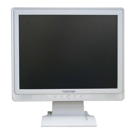
LCD-AD174TW
THESE
DOCUMENTS
ARE
FOR
REPAIR
SERVICE
INFORMATION
ONLY.EVERY
REASONABLE EFFORT HAS BEEN MADE TO ENSURE THE ACCURACY OF THIS MANUAL;
WE CANNOT GUARANTEE THE ACCURACY OF THIS INFORMATION AFTER THE DATE OF
PUBLICATION AND DISCLAIMS RELIABILITY FOR CHANGES, ERRORS OR OMISSIONS.
MANUFACTURE DATA :Jul-25-2006
AD174TW TOSHIBA
Page 1 of 62
Advertisement
Table of Contents

Related Manuals for Toshiba LCD-AD174TW


Summary of Contents for Toshiba LCD-AD174TW
-
Page 1: Service Manual
SERVICE MANUAL TOSHIBA LCD-AD174TW THESE DOCUMENTS REPAIR SERVICE INFORMATION ONLY.EVERY REASONABLE EFFORT HAS BEEN MADE TO ENSURE THE ACCURACY OF THIS MANUAL; WE CANNOT GUARANTEE THE ACCURACY OF THIS INFORMATION AFTER THE DATE OF PUBLICATION AND DISCLAIMS RELIABILITY FOR CHANGES, ERRORS OR OMISSIONS. -
Page 2: Table Of Contents
4.4.2 Optical Characteristics -------------------------------------------------------11 4.4.3 Parameter guide line for CCFL Inverter -----------------------------------12 5. Block Diagram ------------------------------------------------------------------------------13 5.1 Monitor Exploded View -------------------------------------------------------------13 5.2. Disassemble Process --------------------------------------------------------------15 5.3 Software Flow Chart ------------------------------------------------------------------19 5.4. Block Diagram ---------------------------------------------------------------------------21 AD174TW TOSHIBA Page 2 of 62... - Page 3 8.1 Equipments and Tools Requirements -------------------------------------------36 8.2 Trouble Shooting ---------------------------------------------------------------------37 8.2.1 Main Board ---------------------------------------------------------------------37 8.2.2 Key Pad Board ------------------------------------------------------------------39 8.2.3 Power/Inverter Board ------------------------------------------------------40 9. White-Balance, Luminance Adjustment ---------------------------------------------42 10. EDID Content -----------------------------------------------------------------------------44 11. BOM List -----------------------------------------------------------------------------------45 11.1 AD174T——T781KK6NJ4D4ABP ------------------------------------------45~62 AD174TW TOSHIBA Page 3 of 62...
-
Page 4: Revision List
Revision List Revision Date Change Description AD174TW TOSHIBA Page 4 of 62... -
Page 5: Product Feature
Monitor Block Diagram Flat Panel and CCFL Drive. CCFL backlight Main Board Power board RS232 Connector (Include: adapter, inverter) For white balance adjustment in factory mode Keyboard HOST Computer Video signal, DDC AD174TW TOSHIBA Page 5 of 62... -
Page 6: Operation Instructions
Press the power button to turn on the monitor, the power indicator will light up. 3.2 CONTROL BUTTONS 3.2.1 KEY CONTROL Power On/Off OSD Menu Input signal select / Auto Adjustment Volume +, - & Menu Select 3.3 ADJUSTING THE PICTURE AD174TW TOSHIBA Page 6 of 62... -
Page 7: Electrical Performance Parameter
4.1 INPUT SIGNAL CONNECTOR PIN NO. DESCRIPTION PI N NO. DESCRIPTION Red Video Green Video Detect Cable Blue Video RS232 RS232 DDC-Serial Data DDC-Rturn H-Sync R-Ground V-Sync G-Ground DDC-Serial Clock B-Ground VGA Connector layout AD174TW TOSHIBA Page 7 of 62... -
Page 8: Factory Preset Display Modes
48.363 60.004 65.000 1024x768@70Hz 1328x806 56.476 70.069 75.000 1024x768@75Hz 1312x800 60.023 75.029 78.750 1280x1024@60Hz 1688x1066 63.981 60.020 108.000 SXGA 1280x1024@75Hz 1688x1066 79.976 75.025 135.000 1152x864@75HZ 1600x900 67.500 75.000 108.00 1280x960@60HZ 1800x1000 60.000 60.000 108.00 AD174TW TOSHIBA Page 8 of 62... -
Page 9: Power Supply
< 55A peak at 240 VAC and cold starting Leakage Current <3.5 mA MAX No advance effects (no loss of information or defect) Power line surge with a maximum of 1 half-wave missing per second AD174TW TOSHIBA Page 9 of 62... -
Page 10: Inverter Max Brightness
Vrms RL=100KΩ H.V Load Vload Vrms RL=100KΩ 4.4 PANEL SPECIFICATION 4.4.1 General Feature ( BOE HT170E13-101 ) Specification Parameter Unit 337.92(H)x 270.336(V) Active area 1280(H)x 1024(V) Number of pixels pixels 0.264(H)x 0.264(V) Pixel Pitch AD174TW TOSHIBA Page 10 of 62... -
Page 11: Optical Characteristics
0.677 (Center) Reproduction of 0.307 0.337 0.367 Normal Note 5 color 0.253 0.283 0.313 Viewing Green 0.570 0.600 0.630 0.112 0.142 0.172 Blue 0.054 0.084 0.114 Response time Note 6 Cross talk Note 7 AD174TW TOSHIBA Page 11 of 62... -
Page 12: Parameter Guide Line For Ccfl Inverter
Back-light Lamp Current mArms Back-light Lamp operating Note 2 Frequency 1400 Vrms 25℃,Note 3 Lamp Start Voltage 1700 Vrms 0℃,Note 3 Lamp Life 40000 50000 =6.5mA 3.75 Power Consumption 18.33 =6.5mA,Note 4 22.1 22.83 total AD174TW TOSHIBA Page 12 of 62... -
Page 13: Block Diagram
5. BLOCK DIAGRAM 5.1 MONITOR EXPLODED VIEW AD174TW TOSHIBA Page 13 of 62... - Page 14 AUPC780A0DP 1PCS MAIN PCB CBPC780KK5DAP 1PCS PANEL-BKT-L J15G6208-L-2A 1PCS RUBBER FOOT 12G394-3 4PCS STAND Ass’y LIST BASE 34G1547-UU-L 1PCS SCREW M1G340-8-120 4PCS STAND 34G1546-UU-L 1PCS CLAMP 37G4695-1-C 1PCS HINGE 37G6033-2 1PCS SCREW M1G330-6-120 3PCS AD174TW TOSHIBA Page 14 of 62...
-
Page 15: Disassemble Process
8、 Remove the bezel, showed in Fig.17. Do not scratch the panel. 9、 Disassemble the screws that fix the panel, showed in Fig.18,19. 10、 That’s all, the process is over. 5.2.3 Pictures: Cushion (Fig.1) (Fig.2) AD174TW TOSHIBA Page 15 of 62... - Page 16 (Fig.3) (Fig.4) (Fig.5) (Fig.6) (Fig.7) (Fig.8) (Fig.9) (Fig.10) AD174TW TOSHIBA Page 16 of 62...
- Page 17 (Fig.11) (Fig.12) (Fig.13) (Fig.14) (Fig.15) (Fig.16) (Fig.17) AD174TW TOSHIBA Page 17 of 62...
- Page 18 (Fig.18) (Fig.19) (Fig.20) AD174TW TOSHIBA Page 18 of 62...
-
Page 19: Software Flow Chart
5.3 SOFTWARE FLOW CHART AD174TW TOSHIBA Page 19 of 62... - Page 20 16) Display "No connection Check Signal Cable" message. And go into standby mode after the message disappear. 17) Program the scalar to be able to show the coming mode. 18) Process the OSD display. 19) Read the keyboard. Is the power key pressed ? AD174TW TOSHIBA Page 20 of 62...
-
Page 21: Block Diagram
5.4.1 ELECTRICAL BLOCK DIAGRAM LCD Interface Flash Memory Scalar TSUM57AK (Include:MCU,ADC,OSD) H-SYNC Crystal EPR_SDA V-SYNC 14.31818MHz EPR_SCL OSD Control EEPROM D-Sub Interface 24C16 Connector Connector (Key pad) DB7_SDA DB15_SDA DB6_SCL DB15_SCL EEPROM EEPROM 24C02 24C02 AD174TW TOSHIBA Page 21 of 62... -
Page 22: Inverter/Power Board Block Diagram
5.4.2 INVERTER/POWER BOARD BLOCK DIAGRAM Inverter Block Diagram AD174TW TOSHIBA Page 22 of 62... - Page 23 Power Block Diagram AD174TW TOSHIBA Page 23 of 62...
-
Page 24: Schematic
+12V 5.PANEL INTERFACE PC5V VCTRL VCTRL +3V3 VCC1.8 Adj_BACKLIGHT Adj_BACKLIGHT VCC5V VCC3.3 VLCD VLCD_12V Title 4.SCALER VLCD TSUM57AK VLCD_12V Size Document Number 2.POWER Date: Monday , May 30, 2005 Sheet AD174TW TOSHIBA Page 24 of 62... -
Page 25: Main Board
OUT-R- KEY _AUTO KEY _MENU Q404 C431 KEY _RIGHT KEY _LEFT PMBS3904 POWER KEY _C OUT-R+ CONN OUT-L+ OUT-L- OUT-R- Title TSUM57AK CONN Size Document Number SCALER Date: Monday , May 30, 2005 Sheet AD174TW TOSHIBA Page 25 of 62... -
Page 26: Panel Interface
CPT 17 3.3V 3.3V INNOLUX 15 HannStar 15 3.3V 3.3V CPT 15 3.3V 3.3V LG 15 3.3V 3.3V 3.3V Innolux 17" Title TSUM57AK Size Document Number PANEL INTERFACE Date: Monday , May 30, 2005 Sheet AD174TW TOSHIBA Page 26 of 62... - Page 27 1/16W C715 Q707 on_Panel_12V PMBS3904 0.1uF C718 0.1uF C717 R727 PMBS3904 C720 C719 R728 0.1uF 10uF/16V 1/16W Title NC/0.1uF NC/10uF/16V NC/4K7 TSUM57AK Size Document Number POWER Date: Monday , May 30, 2005 Sheet AD174TW TOSHIBA Page 27 of 62...
- Page 28 1/16W ESD_5V C447 C448 C449 C450 C451 C452 C453 C454 Title D425 TSUM57AK 0.1uF 0.1uF 0.1uF 0.1uF 0.1uF 0.1uF 0.1uF 0.1uF RLZ36B Size Document Number INPUT Date: Monday , May 30, 2005 Sheet AD174TW TOSHIBA Page 28 of 62...
-
Page 29: Pwpc Board
6.3 PWPC BOARD 6.3.1 ADAPTER AD174TW TOSHIBA Page 29 of 62... - Page 30 6.3.2 INVERTER AD174TW TOSHIBA Page 30 of 62...
-
Page 31: Keypad Board
6.4 KEYPAD BAORD AD174TW TOSHIBA Page 31 of 62... -
Page 32: Audio Board
6.5 AUDIO BOARD AD174TW TOSHIBA Page 32 of 62... -
Page 33: Pcb Layout
7. PCB LAYOUT 7.1 MAIN BOARD 715G1558-1-IO AD174TW TOSHIBA Page 33 of 62... - Page 34 AD174TW TOSHIBA Page 34 of 62...
-
Page 35: Inverter/Power Board
7.2 INVERTER/POWER BOARD 715G1236-1-IO AD174TW TOSHIBA Page 35 of 62... -
Page 36: Keypad Board
7.3KEYPAD BOARD 715G1496-1-4 7.4 AUDIO BOARD 715G1144-4-NMV 8. MAINTAINABILITY 8.1 EQUIREMENT AND TOOLS REQUIREMENT 1、Voltmeter. 2、Oscilloscope. 3、Pattern Generator. 4、DDC Tool with a Compatible Computer. 5、Alignment Tool. 6、LCD Color Analyzer. 7、Service Manual. 8、User Manual. AD174TW TOSHIBA Page 36 of 62... -
Page 37: Trouble Shooting
Replace Power board and Check Replace U401 (TSUM57AK) Inverter control relative circuit Re-do White balance adjust Note:1. If replace “MAIN-BOARD” , Please re-do “DDC-content” programmed & “WHITE-Balance”. 2. If replace “Power Board” only, Please re-do “ WHITE-Balance” AD174TW TOSHIBA Page 37 of 62... - Page 38 If Bklt-On no-response when the power switch Pin10 PWM signal control dim 0V-5V turn on-off, Replace U401 TUSM57AK Replace power board to new-one and check Replace Power board the screen is normal? & Re-do white balance AD174TW TOSHIBA Page 38 of 62...
-
Page 39: Keypad Board
OSD is unstable or not working Connect Key Pad Board Is Key Pad Board connecting normally ? Replace Button Switch Is Button Switch normally ? Replace Key Pad Board Is Key Pad Board normally ? Check Main Board AD174TW TOSHIBA Page 39 of 62... -
Page 40: Power/Inverter Board
Repeating the start voltage Check the auxiliary voltage is bigger than 10V smaller than 20V 1) Check IC901 2) Check ZD901, Q902, Q903…OVP circuit Check IC901 pin8 PWM wave Check IC 901 Check Q903,R919, T901,D910,D912,ZD904 AD174TW TOSHIBA Page 40 of 62... - Page 41 Check the pin19/20 of U201 have saw tooth wave Check ZD201/ZD202 Check the resonant wave of pin2 & pin5 for PT201 Check Q204/Q208 Check the output of PT201 Change PT201 Check connecter & lamp AD174TW TOSHIBA Page 41 of 62...
-
Page 42: White-Balance, Luminance Adjustment
6、Adjust the BLUE of 9300K on factory window until chroma 7120 indicator reached the value B=100 7、Repeat above procedure ( item 4,5,6) until chroma 7120 RGB value meet the tolerance =100±2 B、Adjust 7200K color-temperature 1、Switch the Chroma-7120 to RGB-Mode (with press “MODE” button ) AD174TW TOSHIBA Page 42 of 62... - Page 43 6、Adjust the BLUE of SRGB on factory window until chroma 7120 indicator reached the value B=100 7、Repeat above procedure ( item 4,5,6) until chroma 7120 RGB value meet the tolerance =100±2 E、Press reset key and Turn the Power-button “off to on” to quit from factory mode. AD174TW TOSHIBA Page 43 of 62...
-
Page 44: Edid Content
10. EDID CONTENT EDID CONTENT——Analog BF EF 00 BC 34 FD 00 EDID CONTENT——DVI BF EF 00 FD 00 AD174TW TOSHIBA Page 44 of 62... -
Page 45: Bom List
PAPER PLATE 0.078 44G8025 15 IO EVA WASHER 44G8759 1 EPS(L) 44G8759 2 EPS(R) 44G9003194 CORNER PAPER 0.061 45G 76 34 TS PE BAG FOR BASE 45G 77 3 TRANSPARENT SHEET 45G 77500 BARCODE RIBBON AD174TW TOSHIBA Page 45 of 62... - Page 46 PANEL BRACKET J15G6208 R 2A PANEL BRACKET J34G1545 UU FB REAR COVER J41G7801939 3A WARRANTY CARD J52G8025800 TO INSULATE SHEET J85G8121 3A PANEL BRACKET C 44G8759939 1A CARTON PARENT NO : AUPC780AOTP AUPC BOARD AD174TW TOSHIBA Page 46 of 62...
- Page 47 67G 309109 7T6371 1.0UF +-20% 50V XINDECO C210 67G 309109 7T6371 1.0UF +-20% 50V XINDECO J201 95G 90 23 TINCOATEDCOPPER J202 95G 90 23 TINCOATEDCOPPER J203 95G 90 23 TINCOATEDCOPPER J204 95G 90 23 TINCOATEDCOPPER AD174TW TOSHIBA Page 47 of 62...
- Page 48 Q701 57G 417 4 PMBS3904/PLILIPS Q703 57G 417 4 PMBS3904/PLILIPS Q706 57G 417 4 PMBS3904/PLILIPS Q401 57G 417 6 PMBS3906 PNP Q403 57G 417 6 PMBS3906 PNP Q702 57G 417 17 T PZT2907A SOT-223 AD174TW TOSHIBA Page 48 of 62...
- Page 49 CHIPR 100OHM +-5% 1/10W R455 61L0603101 CHIPR 100OHM +-5% 1/10W R456 61L0603101 CHIPR 100OHM +-5% 1/10W R458 61L0603101 CHIPR 100OHM +-5% 1/10W R704 61L0603101 CHIPR 100OHM +-5% 1/10W R430 61L0603102 CHIPR 1KOHM +-5% 1/10W AD174TW TOSHIBA Page 49 of 62...
- Page 50 CHIP 1.5KOHM 1/16W 1% R703 61L0603202 CHIPR 2KOHM+-5%1/10W R417 61L0603203 CHIPR 20KOHM +-5% 1/10W R448 61L0603222 CHIPR 2.2KOHM+-5%1/10W R449 61L0603222 CHIPR 2.2KOHM+-5%1/10W R405 61L0603223 CHIPR 22K OHM +-5% 1/10W R403 61L0603390 0F 390OHM +-1% AD174TW TOSHIBA Page 50 of 62...
- Page 51 65G0603104 32 CHIP 0.1UF 50V X7R C430 65G0603104 32 CHIP 0.1UF 50V X7R C439 65G0603104 32 CHIP 0.1UF 50V X7R C440 65G0603104 32 CHIP 0.1UF 50V X7R C441 65G0603104 32 CHIP 0.1UF 50V X7R AD174TW TOSHIBA Page 51 of 62...
- Page 52 71G 56Z601 2.0X1.2 100M=600OHM FB406 71G 56Z601 2.0X1.2 100M=600OHM FB407 71G 56Z601 2.0X1.2 100M=600OHM FB408 71G 56Z601 2.0X1.2 100M=600OHM FB401 71G 56Z601 M CHIP BEAD 0805 600OHM FB402 71G 56Z601 M CHIP BEAD 0805 600OHM AD174TW TOSHIBA Page 52 of 62...
- Page 53 93G 39S 45 T RLZ36B ZENER DIODE D402 93G 39S 45 T RLZ36B ZENER DIODE D425 93G 39S 45 T RLZ36B ZENER DIODE D704 93G1004 4 SCHOTTKY DIODE 1A 40V SM 715G1558 1 IO MAIN PCB AD174TW TOSHIBA Page 53 of 62...
- Page 54 73G 253 91 LS CHOKE COIL L904 73G 253 91 LS CHOKE COIL L901 73L 174 26H1G 线性滤波器 L901 73L 174 26LSG LINE FILTER L901 73L 174 26T1G 阻流圈 L902 73L 174 53 LG GP LINE FILTER AD174TW TOSHIBA Page 54 of 62...
- Page 55 PDTA144WK SOT 346 Q207 57G 760 5B PDTC144WK SOT 346 C232 61L0603303 CHIP 30K OHM 5% 1/10W R927 61L0805000 Chip Resistors 0OHM R216 61L0805100 4F CHIPR 1M OHM +-1% 1/8W R912 61L0805101 CHIPR 100OHM+-5%1/8W AD174TW TOSHIBA Page 55 of 62...
- Page 56 CHIRP 470 K OHM +-5% 1/8 R222 61L0805513 CHIP 51KOHM 1/8W R217 61L0805619 2F CHIPR 62KOHM +-1% 1/8W R212 61L0805622 CHIP 6.2K OHM 1/8W R228 61L0805622 CHIP 6.2K OHM 1/8W R219 61L0805912 CHIP 9.1KOHM 5% 0805 1/ AD174TW TOSHIBA Page 56 of 62...
- Page 57 65G0805105 22 CHIP 1UF 25V X7R 0805 C224 65G0805332 22 CHIP 0.0033UF 25V X7R C216 65G0805392 32 3900PF/50V C930 65G0805471 21 CHIP 470PF 25V NPO 0805 C228 65G0805472 31 CHIP 4700PF 50V X7R 080 AD174TW TOSHIBA Page 57 of 62...
- Page 58 BAV99 SOT-23 D210 93G 6433P BAV99 SOT-23 ZD904 93G 39S 19 T PTZ7.5B ZD201 93G 39S 24 T RLZ5.6B ROHM ZD202 93G 39S 24 T RLZ5.6B ROHM ZD203 93G 39S 24 T RLZ5.6B ROHM AD174TW TOSHIBA Page 58 of 62...
- Page 59 95G 90 23 TINCOATEDCOPPER J903 95G 90 23 TINCOATEDCOPPER J904 95G 90 23 TINCOATEDCOPPER J905 95G 90 23 TINCOATEDCOPPER J906 95G 90 23 TINCOATEDCOPPER J907 95G 90 23 TINCOATEDCOPPER J908 95G 90 23 TINCOATEDCOPPER AD174TW TOSHIBA Page 59 of 62...
- Page 60 65G 3J2206EM 22PF 5% 3KV MURATA C236 65G 3J2206EM 22PF 5% 3KV MURATA C238 65G 3J2206EM 22PF 5% 3KV MURATA C204 65G 3J2206ET 22PF 5% 3KV TDK C208 65G 3J2206ET 22PF 5% 3KV TDK AD174TW TOSHIBA Page 60 of 62...
- Page 61 POWER MOSFET STP8NK80ZFP Q903 57G 667 20 AP2761I-A TO-220CFM 90G6064 1 HEAT SINK XN01A M1G1730 8120 SCREW PARENT NO : 705L 780 71 01 FB901 ASS'Y FB901 71G 55 29 Φ3.5*Φ0.8*2.2\ 100MM> 96G 29 1 H.S.TUBE AD174TW TOSHIBA Page 61 of 62...
- Page 62 PARENT NO : 705L 780 9309A D910/D911 ASS'Y 51G 200 1 散热油 0.02 90G6064 1 HEAT SINK D911 93G 60237 DIODE SRF20100C D910 93G 60245 DIODE SP10150 ITO-220 XN01A M1G1730 8120 SCREW AD174TW TOSHIBA Page 62 of 62...
Need help?
Do you have a question about the LCD-AD174TW and is the answer not in the manual?
Questions and answers