Advertisement
Quick Links
Advertisement

Subscribe to Our Youtube Channel
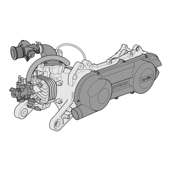
Summary of Contents for APRILIA Air-injection 50 cc
- Page 1 aprilia...
-
Page 3: Carbon Monoxide
WASTE TRANSMISSION OIL CARBON MONOXIDE Use latex gloves for maintenance operations If the engine must be switched on to carry out certain involving contact with oil. If left in contact with the operations make sure the room is well ventilated or skin for long periods, used engine oil can cause open to the outside. -
Page 4: Before Disassembly
Do not clean bearings with compressed air. IMPORTANT Bearings must rotate freely, without sticking or noise. Replace if necessary. - Use only ORIGINAL Aprilia SPARE PARTS. - Stick to the oil chart and recommended wearing parts. - Wherever possible, lubricate parts before reassembling them. - Page 10 Ω a 20° C...
- Page 17 TROUBLESHOOTING SHAFT (DOUBLE CHECK THE MALFUNCTION BEFORE REPLACING ANY PART) FUNCTIONAL PHASE 1 - Turn the key to the “ON” position When the start button is pressed, does the engine turn over? 2 - Does the control LED stay on?
- Page 18 (DOUBLE CHECK THE MALFUNCTION BEFORE REPLACING ANY PART) - Make sure the battery is charged 4 - Does the starter motor work properly when you press If the starter motor does not start or turns slowly - Check battery connections...
- Page 19 (DOUBLE CHECK THE MALFUNCTION BEFORE REPLACING ANY PART) Has the pre-delivery procedure been followed for a new vehicle? 6 - Does the engine idle normally? 1- Prime the petrol pump (each time it is replaced) by: a) switching to “ON”...
- Page 20 (DOUBLE CHECK THE MALFUNCTION BEFORE REPLACING ANY PART) - General check-up with Game-Boy and Check mechanical parts 7 - Does the vehicle accelerate normally (minimum reset errors (butterfly valve at “O” if - Are all transmission parts (clutch, belt, rollers, variator) working...
- Page 21 (DOUBLE CHECK THE MALFUNCTION BEFORE REPLACING ANY PART) - General check-up with Game-Boy and Check mechanical parts 9 - Half-open the throttle: does the vehicle maintain speed? reset errors (butterfly valve at “O” if - Are all transmission parts (belt, variator) working properly?
- Page 22 (DOUBLE CHECK THE MALFUNCTION BEFORE REPLACING ANY PART) - General diagnostics by Game-boy Check mechanical parts 11 - Does the engine work properly ticking over at minimum? - Check the battery voltage - Is the compression ratio right? (piston rings,...
- Page 23 (DOUBLE CHECK THE MALFUNCTION BEFORE REPLACING ANY PART) CHECKING THE PRESSURE OF THE AIR AND FUEL CIRCUITS Fit the pressure gauge to the petrol circuit, between fuel pump and fuel rail To discharge air from the circuit: - switch to “ON”...
- Page 24 (DOUBLE CHECK THE MALFUNCTION BEFORE REPLACING ANY PART) Check: During cranking check the maximum Attach pressure gauge to air circuit - the reed pack compressor pressure, blocking the delivery - hoses hose between the pressure gauge fuel rail. - oil seals and bearings...
- Page 25 (DOUBLE CHECK THE MALFUNCTION BEFORE REPLACING ANY PART) TABLE OF FAULT CODES FLASHING NUMBER DESCRIPTION OF FAULTS FAULT PRIORITY ENGINE CHECK POSSIBLE CAUSE CHECKS AND REMEDIES Damaged thermostat Check thermostat Overheated engine Damaged radiator Check radiator Damaged hose Check hose...
- Page 26 (DOUBLE CHECK THE MALFUNCTION BEFORE REPLACING ANY PART) DESCRIPTION OF FAULTS FAULT PRIORITY ENGINE CHECK POSSIBLE CAUSE CHECKS AND REMEDIES FLASHING NUMBER Check the battery charge. Check and restore battery Battery voltage too low connections if necessary. Check the continuity (R=0 Ohm) of the red/brown wire.
- Page 27 (DOUBLE CHECK THE MALFUNCTION BEFORE REPLACING ANY PART) FLASHING NUMBER DESCRIPTION OF FAULTS FAULT PRIORITY POSSIBLE CAUSE CHECKS AND REMEDIES ENGINE CHECK Connectors Check connectors Check the continuity (R=0 Ohm) of the yellow/red wire between the fuel injector and ECU. Check the voltage...
- Page 28 (DOUBLE CHECK THE MALFUNCTION BEFORE REPLACING ANY PART) FLASHING NUMBER DESCRIPTION OF FAULTS FAULT PRIORITY POSSIBLE CAUSE CHECKS AND REMEDIES ENGINE CHECK Rev limit switch triggered Maximum speed limit Led for rev limit switch (if on, does not indicate a fault)
-
Page 29: Disassembly Sequence
DISASSEMBLY SEQUENCE V-BELT – CLUTCH – PRIMARY AND SECONDARY PULLEY Remove the 8 screws (1) retaining the T sleeves (1A), loosen 10 Nm (1 kgm) the clamp (1B) and remove the variator cover (2). Remove the 6-sided nut (3), spacer 4), toothed cup (5) spacer (6). - Page 30 : New item DISASSEMBLY SEQUENCE : Engine oil O.C. : Gearbox oil COOLING UNIT : Molybdenum bisulphuroil : Grease Remove the 4 screws (1) and aeration cover (2). : Loctite Remove the 2 screws (3) and fan conveyor (4). Remove the 3 screws (5), retain the T sleeves (6) and remove the fan (7).
- Page 31 DISASSEMBLY SEQUENCE INJECTION UNIT Empty the fuel tank Disconnect the wires Remove the 2 flanged screws (1). Remove the input valve (2). Remove the air injector using the proper tool (3). Slide off the O rings (4), (5). DANGER If connector hoses are removed (after removing the clamps), be very careful when refitting the high pressure hose (6) (maximum pressure 8-10 bar).
- Page 32 DISASSEMBLY SEQUENCE HEAD – CYLINDER – PISTON Remove the 2 screws (1), retain the 2 T sleeves (2). Remove the 2 screws (3). Remove the LH cylinder cover (4) and RH cover (5). Remove spark plug (6) and thermostat (7). Remove the four tightening head nuts (8).
- Page 33 DISASSEMBLY SEQUENCE 4-5 Nm (0,4-0,5 kgm) AIR COMPRESSOR Remove the 4 screws (1) without losing the washers (2). Remove the compressor (3) from the guard. Remove the OR (4). Unscrew the compressor connector (5). COVER AND CRANKCASE Remove the six cover screws (6). Separate the RH half (7) from the LH half (8) of the cover.


Need help?
Do you have a question about the Air-injection 50 cc and is the answer not in the manual?
Questions and answers