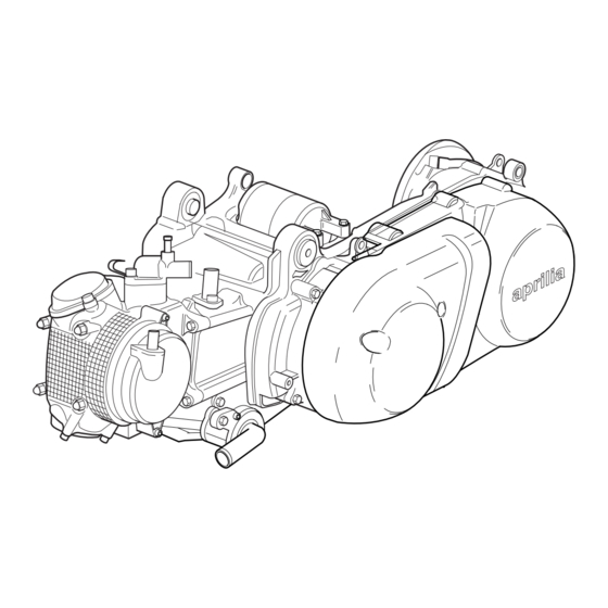
Summary of Contents for APRILIA YP 250 4T
- Page 2 Products or services manufactured or provided by third parties are quoted merely as examples and do not constitute a recommendation; Aprilia s.p.a. is not liable for the performance or use of such products and services. Second edition. May 2000.
-
Page 3: Carbon Monoxide
GENERAL PRECAUTIONS AND INFORMATION CARBON MONOXIDE For repair and disassembly and reassembly operations If the engine must be switched on to carry out certain follow this instructions. operations make sure the room is well ventilated or open to the outside. Never switch on the engine in a closed room, unless there is a smoke and fume removal system installed and the operating. - Page 4 Replace if necessary. for one part anti-freeze (50%) . This mixture is suitable for most operating temperatures -Use only ORIGINAL Aprilia SPARE PARTS. and also guarantees good rust protection. -Stick to the oil chart and recommended wearing parts.
- Page 5 aprilia...
- Page 6 aprilia...
- Page 7 "C" "B" "D" "A"...
- Page 8 aprilia...
- Page 9 aprilia...
- Page 10 aprilia...
- Page 11 aprilia...
- Page 12 Refrigeration liquid for the engine (recommended):...
- Page 13 aprilia...
- Page 14 aprilia...
- Page 15 aprilia...
- Page 16 aprilia...
- Page 17 MICRO SWITCH QUALITY MEASUREMENT SYSTEM...
- Page 18 QUALITY MEASUREMENT SYSTEM...
-
Page 19: Disassembly Sequence
DISASSEMBLY SEQUENCE O.C. REMOVING THE TRAPEZOID BELT, THE CLUTCH AND PRIMARY/SECONDARY PULLEY. Remove the variator cap (2) screws (1) and gasket O.C. Remove the 6-sided nut (3) and washer (4) 16 Nm (1.6 Kgm) Remove the primary fixed pullet (5) O.C. - Page 20 8 Nm (0,8 Kgm) DISASSEMBLY SEQUENCE 8 Nm (0,8 Kgm) CYLINDER HEAD Remove the oil discharge cap (1A) Remove the distributor cap (1) and O-ring (2) Remove the valve cap on the aspiration side (3) and discharge side (4) Remove the chain stretching unit (5) Remove the breather plate (6) 23 25 26 Remove the distribution gear (7)
- Page 21 DISASSEMBLY SEQUENCE 80 Nm (8.0 Kgm) GENERATOR C.A AND CLUTCH STARTER Disconnect the connectors (1) Remove the screws (2) and flywheel cap (3) 7 Nm (0,7 Kgm) Remove the gasket (4) and the centering pins (5) Remove the complete stator (6) Remove the rotor (7) Slide off the shaft (neutral gear) (8) and remove the neutral gear (9)
- Page 22 DISASSEMBLY SEQUENCE 7 Nm (0,7 Kgm) OIL PUMP Remove the generator (see table no. 03) Remove the screws (1) and the cap (2) Remove the oil pump gear (3) and its pin (4) Remove the oil pump unit (5) and gasket (6) Remove the water pump shaft gear (7) and centering pin (8) Remove the shaft (9) WATER PUMP...


Need help?
Do you have a question about the YP 250 4T and is the answer not in the manual?
Questions and answers