Table of Contents
Advertisement
CAUTION, MICROWAVE RADIATION ............................................................................................................. 1
WARNING .......................................................................................................................................................... 1
PRODUCT SPECIFICATIONS ......................................................................................................................... 2
GENERAL INFORMATION ................................................................................................................................ 2
APPEARANCE VIEW ....................................................................................................................................... 3
OPERATION SEQUENCE ................................................................................................................................ 4
FUNCTION OF IMPORTANT COMPONENTS ................................................................................................ 6
SERVICING ...................................................................................................................................................... 7
TEST PROCEDURE ......................................................................................................................................... 9
TOUCH CONTROL PANEL ............................................................................................................................. 16
COMPONENT REPLACEMENT AND ADJUSTMENT PROCEDURE ........................................................... 21
MICROWAVE MEASUREMENT .................................................................................................................... 27
WIRING DIAGRAM ......................................................................................................................................... 28
PICTORIAL DIAGRAM ................................................................................................................................... 29
POWER UNIT CIRCUIT .................................................................................................................................. 30
CPU UNIT CIRCUIT ........................................................................................................................................ 31
PRINTED WIRING BOARD ............................................................................................................................. 32
PARTS LIST ................................................................................................................................................... 33
SERVICE MANUAL
Info Display
HELP
SENSOR INSTANT REHEAT
DINNER
CASSEROLE
PLATE
SOUP
PIZZA
RICE
PIE
MODEL
S E N S O R
C O O K
VEGETA BLES
RICE/PA STA
MEAT
DESSER TS
EXPRESS
EASY
DEFROST
LESS
MORE
DEFROST
SLOW
QUICK &
COOK
EASY
POWE R
LEVEL
CLOCK
TIME R
STOP
STOP
INSTA NT
INST
ANT COOK
COOK
CLEA R
CLEA R
ST
STAR T
ART
In interests of user-safety the oven should be restored to its
original condition and only parts identical to those specified
should be used.
TABLE OF CONTENTS
SHARP CORPORATION
39
MICROWAVE OVEN
R-380E
R-380E
S7107R380EPJ/
Page
Advertisement
Table of Contents

Related Manuals for Sharp R-380E


Summary of Contents for Sharp R-380E
-
Page 1: Table Of Contents
R-380E SERVICE MANUAL S7107R380EPJ/ MICROWAVE OVEN Info Display HELP SENSOR INSTANT REHEAT R-380E DINNER CASSEROLE PLATE SOUP PIZZA RICE MODEL S E N S O R C O O K VEGETA BLES RICE/PA STA MEAT DESSER TS EXPRESS EASY DEFROST... - Page 2 R-380E...
-
Page 3: Caution Microwave Radiation
MICROWAVE OVEN R-380E APPEARANCE VIEW GENERAL IMPORTANT INFORMATION This Manual has been prepared to provide Sharp Corp. Service OPERATING SEQUENCE engineers with Operation and Service Information. It is recommended that service engineers carefully study the entire text of this manual, so they will be qualified to render FUNCTION OF IMPORTANT satisfactory customer service. -
Page 4: Product Specifications
R-380E PRODUCT SPECIFICATIONS ITEM DESCRIPTION Power Requirements 230 - 240 Volts 50 Hertz Single phase, 3 wire earthed Power Consumption 1.7kW Power Output 1150 watts nominal of RF microwave energy (IEC Test Procedure) Operating frequency 2450 MHz Case Dimensions Width 520 mm... -
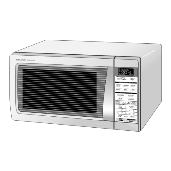
Page 5: Appearance View
R-380E APPEARANCE VIEW 1. Door handle 2. Oven lamp 3. Door hinges 4. Door safety latches 10.Digital readout 5. See through door 11.Ventilation openings 6. Door seals and sealing surfaces 12.Power supply cord 7. Coupling 13.Turntable tray 8. Wave guide cover 14.Turntable support... -
Page 6: Operation Sequence
R-380E OPERATION SEQUENCE OFF CONDITION because the relay RY1 stays closed. Shown in the display is the remaining time. Closing the door activates all door interlock switches (1st. latch switch and 2nd. interlock relay control switch). MONITOR SWITCH CIRCUIT IMPORTANT... - Page 7 R-380E 2. Heat potatoes. Moisture and humidity is emitted rapidly. You can smell the aroma as it cooks. 3. Sensor detects moisture and humidity and calculates cooking time and variable power. AH SENSOR Cooking Sequence. 1. Touch each SENSOR COOK or SENSOR INSTANT REHEAT function pad to operating the sensor cooking.
-
Page 8: Function Of Important Components
R-380E FUNCTION OF IMPORTANT COMPONENTS DOOR OPEN MECHANISM OVEN THERMAL CUT-OUT The door is opened by pulling the door, refer to the Figure The thermal cut-out, located on the top of the oven cavity, D-1. is designed to prevent damage to the oven by fire. If the... -
Page 9: Servicing
If the water remains cold carry out 3D checks and re- examine the connections to the component being Sharp recommend that wherever possible fault-finding tested. is carried out with the supply disconnected. It may in, some cases, be necessary to connect the supply after... - Page 10 R-380E CK = Check / RE = Replace TEST PROCEDURE A B C D E E E G F H H I L M N O J K P RE CK CK RE CK CKCK CK CK POSSIBLE CAUSE DEFECTIVE PARTS...
-
Page 11: Test Procedure
R-380E TEST PROCEDURES PROCEDURE COMPONENT TEST LETTER MAGNETRON TEST NEVER TOUCH ANY PART IN THE CIRCUIT WITH YOUR HAND OR AN INSULATED TOOL WHILE THE OVEN IS IN OPERATION. CARRY OUT 3D CHECK. Isolate the magnetron from high voltage circuit by removing all leads connected to filament terminal. - Page 12 R-380E TEST PROCEDURES PROCEDURE COMPONENT TEST LETTER Room temperature ....To = 21˚C Initial temperature ....T1 = 11°C Temperature after (36 + 3) = 39 sec..............T2 = 21°C Temperature difference Cold-Warm .............. ∆T1 = 10°C Measured output power The equation is “P = 115 x ∆T”...
- Page 13 R-380E TEST PROCEDURES PROCEDURE COMPONENT TEST LETTER HIGH VOLTAGE CAPACITOR TEST CARRY OUT 3D CHECKS. A. Isolate the high voltage capacitor from the circuit. B. Continuity check must be carried out with measuring instrument which is set to the highest resistance range.
- Page 14 R-380E TEST PROCEDURES PROCEDURE COMPONENT TEST LETTER If incorrect readings are obtained, replace the monitor resistor. CARRY OUT 4R CHECKS. MOTOR WINDING TEST CARRY OUT 3D CHECKS. Disconnect the leads from the motor. Using an ohmmeter, check the resistance between the two terminals as described in the table below.
-
Page 15: Touch Control Panel
R-380E TEST PROCEDURES PROCEDURE COMPONENT TEST LETTER TOUCH CONTROL PANEL ASSEMBLY TEST The touch control panel consists of circuits including semiconductors such as LSI, ICs, etc. Therefore, unlike conventional microwave ovens, proper maintenance cannot be performed with only a voltmeter and ohmmeter. In this service manual, the touch control panel assembly is divided into two... - Page 16 R-380E TEST PROCEDURES PROCEDURE COMPONENT TEST LETTER RY1 and RY2 Relay Test These relays are operated by D.C. voltage. Check voltage at the relay coil with a D.C. voltmeter during the microwave cooking operation. DC. voltage indicated ....Defective relay.
- Page 17 R-380E TEST PROCEDURES PROCEDURE COMPONENT TEST LETTER (8) If the sensor has not detected the vapor of the food, ERROR will appear and the oven will shut off. Water load cooking test WARNING : The oven should be fully assembled before following procedure.
-
Page 18: Touch Control Panel
R-380E TEST PROCEDURES PROCEDURE COMPONENT TEST LETTER (10) Disconnect the power supply cord, and then remove outer case. (11) Open the door and block it open. (12) Discharge high voltage capacitor. (13) Disconnect the dummy resistor circuit from the sensor connector of control panel. - Page 19 R-380E The I/O signal of the LSI is detailed in the following table. Pin No. Signal Description COM5 Common data signal : COM11. Connected to LCD signal COM11. COM4 Common data signal : COM12. Connected to LCD signal COM12. COM3 Common data signal : COM13.
- Page 20 R-380E Pin No. Signal Description Key strobe signal. Signal applied to touch-key section. A pulse signal is input to AIN7, P14, P15, P16 and P17 terminal while one of G6 line keys on key matrix is touched. Key strobe signal.
- Page 21 R-380E Pin No. Signal Description The relation between signals and LCD are as follows: LSI signal LSI signal LSI signal (Pin No.) segment (Pin No.) segment (Pin No.) segment SEG 39 (103) ..SEG 1 SEG 25 (117) ..SEG 15 SEG 12 (130) ..
- Page 22 R-380E TOUCH CONTROL PANEL SERVICING apart from the oven proper; in this case you must short 1. Precautions for Handling Electronic Components both ends of the door sensing switch (on PWB) of the This unit uses CMOS LSI in the integral part of the circuits.
-
Page 23: Component Replacement And Adjustment Procedure
Oven lamp, Magnetron, High voltage transformer manners. and Oven cavity. 1. Before wiring, 3) Sharp edge: 1) Disconnect the power supply. Bottom plate, Oven cavity, Waveguide flange, 2) Open the door and wedge the door open. Chassis support and other metallic plate. - Page 24 R-380E from the noise filter. 9. Disconnect rectifier terminal from capacitor. 4. Disconnect the high voltage fuse from the power Now, the high voltage rectifier assembly is free. transformer. 10.Disconnect high voltage fuse from capacitor. 5. Disconnect filament lead of the power transformer from Now, the high voltage fuse is free.
- Page 25 4. Where the corners have been snipped off bend corner areas flat. No sharp edge must be evident after removal NOTE: The one (1) screw to fit the turntable motor cover of the turntable motor cover.
- Page 26 R-380E CAUTION: 4. Install the fan duct assembly to the oven cavity with the * Do not hit the fan blade strongly when installed one (1) screw. because the bracket may be disfigured. 5. Insert the snap of the main wire harness to the hole of...
-
Page 27: Microwave Measurement
R-380E 1ST. LATCH SWITCH, 2ND. INTERLOCK RELAY CONTROL SWITCH AND MONITOR SWITCH ADJUSTMENT If the 1st. latch switch, 2nd. latch switch, stop switch and door toward the oven face. Both results (play in the monitor switch do not operate properly due to a door) should be less than 0.5mm. - Page 28 R-380E radiation emission limitation standards. SEALER FILM After any service, make sure of the following : Installation 1. Door latch heads smoothly catch latch hook through 1. Put the adhesive tape on the backing film of the sealer latch holes and that latch head goes through center of film as shown in Fig.
-
Page 29: Microwave Measurement
R-380E MICROWAVE MEASUREMENT After adjustment of door latch switches, monitor switch Recommended instruments are: and door are completed individually or collectively, the NARDA 8100 following leakage test must be performed with a survey NARDA 8200 instrument and it must be confirmed that the result meets... -
Page 30: Wiring Diagram
R-380E SCHEMATIC NOTE: CONDITION OF OVEN 1. DOOR CLOSED NOTE: " " indicates components with potentials above 250V. 2. CLOCK APPEARS ON DISPLAY THERMAL NOISE FILTER CUT-OUT 125˚C (OVEN) FUSE M10A N.O. COM. N.O. COM. RY-1 RY-2 H. V. FUSE CONTROL 0.75A... -
Page 31: Pictorial Diagram
R-380E... -
Page 32: Power Unit Circuit
R-380E CN-C 12PIN LEAD WIRE HARNESS Q2 2SB1238 R4 27 R5 4.7k CN-A D1-D4 11ES1 1SS270A 1SS270A – – R3 510 1/2w Q1 2SB1238 R2 680 1/2w SP1 PKM22EPT Q3 KRC243M BUZZER OVEN LAMP R6 3.3k TURNTABLE OVEN LAMP MOTOR... -
Page 33: Cpu Unit Circuit
R-380E... -
Page 34: Printed Wiring Board
R-380E (RED) (GREEN) CN - C SH - B SH - A B R1 (CN - B) (J2) (R9) (D10) (CN - D) (J1) CN - A Figure S-4. Printed Wiring Board... -
Page 35: Parts List
R-380E PARTS LIST ∆ Note: The parts marked " " may cause undue microwave exposure. The parts marked "*" are used in voltage more than 250V. REF. NO. PART NO. DESCRIPTION Q'TY CODE ELECTRIC PARTS 1- 1 QSW-MA137WRE0 1st. latch switch/ 2nd. interlock relay control switch... - Page 36 R-380E ∆ Note: The parts marked " " may cause undue microwave exposure. The parts marked "*" are used in voltage more than 250V. REF. NO. PART NO. DESCRIPTION Q'TY CODE 4-13 PCUSUA511WRP0 Cushion 4-14 PCOVPA349WRE0 Waveguide cover 4-15 PCUSGA339WRP0...
-
Page 37: Oven And Cabinet Parts
R-380E OVEN AND CABINET PARTS 4-13 4-25 4-24 4-18 1-18 1-10 1-11 4-17 4-21 4-16 1-13 4-26 4-11 4-25 4-10 4-19 6-10 4-12 4-15 4-14 4-22 1-17 1-12 1-15 1-14 4-20 4-23 4-15 1-16 4-18... - Page 38 R-380E CONTROL PANEL PARTS DOOR PARTS 5-11 3-3-1 5-10 5-10 MISCELLANEOUS Actual wire harness may be different from illustration.
-
Page 39: Packing And Accessories
R-380E PACKING AND ACCESSORIES TOP PAD ASSEMBLY FPADBA428WRKZ DOOR PROTECTION SHEET SPADPA204WRE0 PLASTIC BAG SSAKHA034WREZ 6- 8 INSTRUCTION BOOK & PRINTING MATTER 6- 2 TURNTABLE TRAY BOTTOM PAD ASSEMBLY FPADBA429WRKZ 6- 1 TURNTABLE SUPPORT TRAY PACK INTO THE SPADFA451WRE0 OVEN CAVITY Not replaceable items. - Page 40 R-380E 2001SHARP CORP. (7K0.300E) Printed in Australia...
Need help?
Do you have a question about the R-380E and is the answer not in the manual?
Questions and answers