Daikin FAQ71CVEB Installation Manual
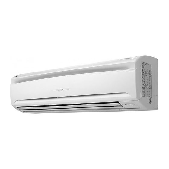
Wall mounted type
Hide thumbs
Also See for FAQ71CVEB:
- Operation manual (19 pages) ,
- Service manual (215 pages) ,
- Service manual (215 pages)
Table of Contents
Advertisement
SPLIT SYSTEM
MODELS
(Wall mounted type)
FAQ71CVEB
FAQ100CVEB
READ THESE INSTRUCTIONS CAREFULLY BEFORE INSTALLATION.
KEEP THIS MANUAL IN A HANDY PLACE FOR FUTURE REFERENCE.
LESEN SIE DIESE ANWEISUNGEN VOR DER INSTALLATION SORGFÄLTIG DURCH.
BEWAHREN SIE DIESE ANLEITUNG FÜR SPÄTERE BEZUGNAHME GRIFFBEREIT AUF.
LIRE SOIGNEUSEMENT CES INSTRUCTIONS AVANT L'INSTALLATION.
CONSERVER CE MANUEL A PORTEE DE MAIN POUR REFERENCE ULTERIEURE.
LEA CUIDADOSAMENTE ESTAS INSTRUCCIONES ANTES DE INSTALAR.
GUARDE ESTE MANUAL EN UN LUGAR A MANO PARA LEER EN CASO DE TENER
ALGUNA DUDA.
PRIMA DELL'INSTALLAZIONE LEGGERE ATTENTAMENTE QUESTE ISTRUZIONI.
TENERE QUESTO MANUALE A PORTATA DI MANO PER RIFERIMENTI FUTURI.
ΔΙΑΒΑΣΤΕ ΠΡΟΣΕΚΤΙΚΑ ΑΥΤΕΣ ΤΙΣ ΟΔΗΓΙΕΣ ΠΡΙΝ ΑΠΟ ΤΗΝ ΕΓΚΑΤΑΣΤΑΣΗ ΕΧΕΤΕ ΑΥΤΟ
ΤΟ ΕΓΧΕΙΡΙΔΙΟ ΕΥΚΑΙΡΟ ΓΙΑ ΝΑ ΤΟ ΣΥΜΒΟΥΛΕΥΕΣΤΕ ΣΤΟ ΜΕΛΛΟΝ.
LEES DEZE INSTRUCTIES ZORGVULDIG DOOR VOOR INSTALLATIE. BEWAAR DEZE
HANDLEINDING WAAR U HEM KUNT TERUGVINDEN VOOR LATERE NASLAG.
LEIA COM ATENÇÃO ESTAS INSTRUÇÕES ANTES DE REALIZAR A INSTALAÇÃO.
MANTENHA ESTE MANUAL AO SEU ALCANCE PARA FUTURAS CONSULTAS.
ПЕРЕД НАЧАЛОМ МОНТАЖА ВНИМАТЕЛЬНО ОЗНАКОМЬТЕСЬ С ДАННЫМИ
ИНСТРУКЦИЯМИ. СОХРАНИТЕ ДАННОЕ РУКОВОДСТВО В МЕСТЕ, УДОБНОМ ДЛЯ
ОБРАЩЕНИЯ В БУДУЩЕМ.
MONTAJDAN ÖNCE BU TALÝMATLARI DÝKKATLÝ BÝR BÝÇÝMDE OKUYUN.
GELECEKTE BAÞVURMAK ÜZERE BU ELKÝTABINI KOLAY ULAÞABÝLECEÐÝNÝZ BÝR YERDE
MUHAFAZA EDÝN.
INSTALLATION MANUAL
Air Conditioners
English
Deutsch
Français
Español
Italiano
Nederlands
Portugues
Advertisement
Table of Contents

Related Manuals for Daikin FAQ71CVEB


Summary of Contents for Daikin FAQ71CVEB
-
Page 1: Installation Manual
English SPLIT SYSTEM Air Conditioners Deutsch MODELS Français (Wall mounted type) FAQ71CVEB Español FAQ100CVEB Italiano READ THESE INSTRUCTIONS CAREFULLY BEFORE INSTALLATION. KEEP THIS MANUAL IN A HANDY PLACE FOR FUTURE REFERENCE. LESEN SIE DIESE ANWEISUNGEN VOR DER INSTALLATION SORGFÄLTIG DURCH. -
Page 2: Table Of Contents
FAQ71CVEB SPLIT SYSTEM Air Conditioner Installation manual FAQ100CVEB CONTENTS 1. SAFETY PRECAUTIONS..................1 2. BEFORE INSTALLATION ..................3 3. SELECTING INSTALLATION SITE..............5 4. PREPARATION BEFORE INSTALLATION............6 5. INDOOR UNIT INSTALLATION ................7 6. REFRIGERANT PIPING WORK.................10 7. DRAIN PIPING WORK ..................12 8. ELECTRIC WIRING WORK ................14 9. - Page 3 • Install the air conditioner on a foundation strong enough to withstand the weight of the unit. If a foundation does not have sufficient strength, the equipment may fall and cause injury. • Carry out the required installation work in consideration of strong winds, typhoons or earthquakes. If the installation work is not properly carried out, the unit may fall down and cause accidents.
-
Page 4: Before Installation
2. BEFORE INSTALLATION Do not exert pressure on the resin parts when opening the unit or when moving it after opening. Be sure to check in advance that the refrigerant to be used for installation is R410A. (If a wrong refrig- erant is charged, the unit will not properly operate.) •... -
Page 5: To Outdoor Unit
NOTE • If the customer wishes to use a remote controller that is not listed above, select a suitable remote controller after consulting catalogs and technical guide. FOR THE FOLLOWING ITEMS, TAKE SPECIAL CARE DURING CONSTRUCTION AND CHECK AFTER INSTALLATION IS FINISHED. 1. -
Page 6: Selecting Installation Site
2-4 NOTE TO THE INSTALLER Be sure to instruct customers how to properly operate the unit (especially cleaning filters, operating different functions, and adjusting the temperature) by having them carry out operations by themselves while reading the manual literally. 3. SELECTING INSTALLATION SITE Do not exert pressure on the resin parts when opening the unit or when moving it after opening. -
Page 7: Preparation Before Installation
(2) Investigate whether the installation location (such as the floor and wall) can bear the weight of the unit and, if necessary, reinforce the location with such as boards and beams before installation. To avoid vibration and abnormal noise, reinforce the location before installation. (3) The indoor unit may not be directly installed on the wall. -
Page 8: Indoor Unit Installation
5. INDOOR UNIT INSTALLATION As for the parts to be used for installation, be sure to use the attached accessories and the specified parts. CAUTION • Install so that the unit does not tilt to either side or forward. (Applying an excessive force to the drain hose can cause water leakage.) •... - Page 9 (2) Remove the front grille. Tab position Tab position (3 places) (4 places) Screw position (6 places) Coin, etc. Grille clamp Screw position positions (3 places) How to remove (3 places) grille clamps (for 100 class only) Front grille securing positions Front grille securing positions Remove the clamps for 71 class...
- Page 10 (3) Hook the indoor unit onto the installation panel. (Refer to Fig. 10) • Placing buffering material between the wall and the indoor unit at this time will make work easier. Hook the indoor unit hook onto the installation panel (1). Control box lid Front grille Front panel...
-
Page 11: Refrigerant Piping Work
(6) Push on both bottom edges of the indoor unit using both hands and hook the tab on the back of the indoor unit onto the installation panel (1). (Refer to Fig. 10) • At this time remove the buffering material placed in step (3). •... - Page 12 Table 2 Pipe size Tightening torque (N·m) Flare dimensions A (mm) Flare φ 9.5 (3/8”) 32.7-39.9 12.8 – 13.2 R0.4-0.8 φ15.9 (5/8”) 61.8-75.4 19.3 – 19.7 • Refer to “Table 2” to determine the proper tightening torque. CAUTION • Overtightening may damage the flare and cause a refrigerant leakage. When you do not have a torque wrench, use Table 2 as a rule of thumb When you keep on tightening the flare nut with a spanner, there is a point where the tightening torque sud- denly increases.
-
Page 13: Drain Piping Work
NOTE 1. For the nitrogen exchange procedures, please refer to the Multi-split Type Series for Building installation manual (contact your Daikin dealer). 2. When brazing after having nitrogen flow through the pipe and substituting nitrogen for air, it is appropriate to set the nitrogen pressure to about 0.02MPa with a pressure reducing valve. - Page 14 • When extending the drain hose, use a commercially available drain extension hose, and be sure to insulate the extended section of the drain hose which is indoor units. (Refer to Fig. 18) Indoor unit drain hose Extension drain piping (commercially available) Insulating tube Insulating tape (accessory) (3)
-
Page 15: Electric Wiring Work
8. ELECTRIC WIRING WORK 8-1 GENERAL INSTRUCTIONS • Electric wiring work must be conducted by an electrician authorized by power companies (Only a licensed electrician is permitted to conduct electric work and earth connections.) • All wiring must be performed by an authorized electrician. •... -
Page 16: How To Connect Wirings And Wiring Example
9. HOW TO CONNECT WIRINGS AND WIRING EXAMPLE 9-1 HOW TO CONNECT WIRINGS Connecting methods of wiring between indoor and outdoor units, earth wiring, and remote controller wiring • Wiring between units and earth wire Connect the wiring between units and earth wire that are drawn into the unit in step “5. INDOOR UNIT INSTALLATION”. - Page 17 Precautions to be taken for power supply wiring Use a round crimp-style terminal for connection to the power supply terminal block. (Refer to Fig. 22) In case it cannot be used due to unavoidable reasons, be sure to observe the following instructions. •...
- Page 18 9-2 WIRING EXAMPLE CAUTION Be sure to install an earth leakage breaker to the outdoor unit. This is to avoid electric shocks or fire. For the wiring of outdoor units, refer to the installation manual attached to the outdoor units. Confirm the system type.
-
Page 19: Note 4)
When implementing group control • When using as a pair unit or as a master unit for simultaneous multiple unit operation, you may carry out simultaneous start/stop (group) control up to 16 units with the remote controller. (Refer to Fig. 27 ) •... -
Page 20: Field Setting
Fig. 30 Fig. 29 Upper case of remote controller (Factory setting) Remote controller printed (Only one remote circuit board controller needs Lower case of to be changed if remote controller factory settings Insert the screwdriver have remained here and gently work untouched.) off the upper part of remote controller. - Page 21 10-1 AIRFLOW SETTINGS WHEN THERMOSTAT IS OFF • Set the flow rate according to the requirement of the environment after consultation with the customer. (As the factory setting, airflow for when cooler thermostat is off is set to SECOND CODE NO. “02”, while other settings are set to “01”.) (Refer to Table 6) Table 6 FIRST...
- Page 22 10-4 SETTING INDOOR UNIT NUMBER OF SIMULTANEOUS OPERATION SYSTEM • When using in simultaneous operation system mode, change the SECOND CODE NO. as shown in Table 9. (SECOND CODE NO. is factory set to “01” for pair system.) Table 9 Setting Mode No.
- Page 23 Main power supply Main power supply Earth leakage Earth leakage ( 3 ) ( 7 ) circuit breaker circuit breaker Outdoor unit Outdoor unit 1 2 3 1 2 3 NOTE) NOTE) 1 2 3 1 2 3 1 2 3 1 2 3 Indoor unit (Master) Indoor unit...
-
Page 24: Test Operation
11. TEST OPERATION 〈 Complete all the “1. Items to be checked after completion of work” on page 4. Please also refer to the 〉 installation manual provided with the indoor unit. The settings of the BRC1E model remote controller should be switched while referring to the manual supplied with the remote controller. - Page 25 When the operation stops due to trouble. the display on the indoor unit flashes. In such a case, diagnose the fault contents with the table on the Error code list looking for the error code which can be found by following procedures. (NOTE 2) (1) Press the INSPECTION /TEST OPERATION button, “...
- Page 26 Abnormal stop is applied depending on the Suction air thermistor malfunction model or condition. Humidity sensor abnormal Intelligent eye / floor temperature sensor malfunction Remote controller air thermistor Remote controller thermo does not function, malfunction but body thermo operation is enabled. Action of safety device (Outdoor unit) Outdoor printed circuit board failure (Outdoor unit)
- Page 27 Discharge pipe pressure sensor system malfunction (Outdoor unit) Suction pipe pressure sensor system malfunction (Outdoor unit) Inverter system malfunction (Outdoor unit) Reactor thermistor malfunction (Outdoor unit) Overheated heat-radiating fin Inverter cooling failure. (Outdoor unit) Instantaneous overcurrent The compressor engines and turbines may be (Outdoor unit) experiencing a ground fault or short circuit.
-
Page 28: Wiring Diagram
CAUTION • Refer to “2. Items to be checked at time of delivery to customer” on page 4 upon completion of the test oper- ation and make sure that all the items are checked. • If the customer’s interior work is not finished on completion of the test operation, tell the customer not to operate the air conditioner. - Page 29 Fig. 34 English...
- Page 30 3P184443-9L EM11A040A (1112) HT...
Need help?
Do you have a question about the FAQ71CVEB and is the answer not in the manual?
Questions and answers