
Related Manuals for Lochinvar EFB Series


Summary of Contents for Lochinvar EFB Series
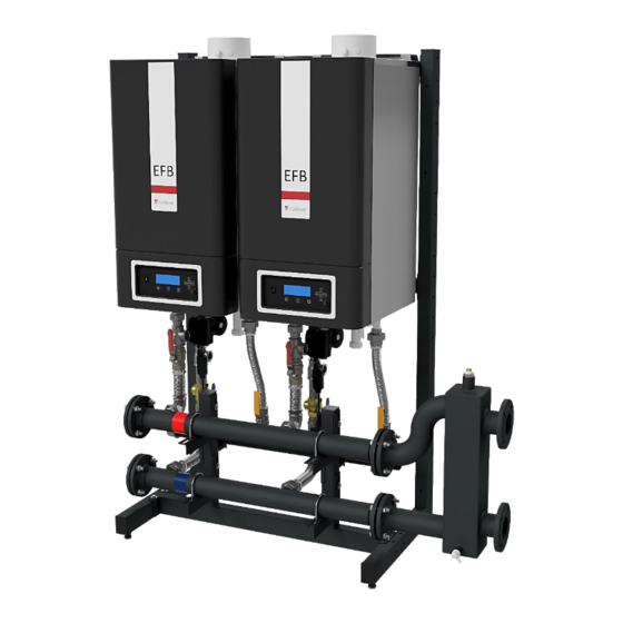
- Page 1 WALL HUNG GAS FIRED CONDENSING BOILERS Cascade pipework headers Installation, Commissioning, User and Maintenance instructions MODELS EFB85 EFB105 EFB125 EFB155 Installation manual_EFB Cascade_June 2019...
-
Page 3: Table Of Contents
Table of Contents INTRODUCTION ............................4 INSTALLATION PROCEDURE CASCADE CONFIGURATION .............. 5 CALCULATE DIMENSIONS AND SPACE OF CASCADE CONFIGURATION........6 EXPLANATION OF PARTS AND GROUPS ..................... 9 CONNECTING SETS ..........................10 HYDRAULIC AND GAS HEADER GROUP .................... 11 Headers ............................11 Support beam and support brackets .................... -
Page 4: Introduction
Lochinvar Limited can supply standard cascade systems with mounting frame, piping and low loss headers for up to six boilers depending on the range. Larger amounts of boilers in a cascade combination are possible but require a dedicated system which must be designed separately. -
Page 5: Installation Procedure Cascade Configuration
2. Installation procedure cascade configuration In order to completely install a cascade configuration of two or more boilers, the following procedure should be observed: 1. Calculate the total required amount of power for the cascade configuration and determine the number of boilers necessary in the cascade configuration to achieve the required power. -
Page 6: Calculate Dimensions And Space Of Cascade Configuration
3. Calculate dimensions and space of cascade configuration This chapter explains how to determine the dimensions of the cascade configuration and how much space is required in the room where the cascade configuration will be installed. Figure 3.1 Dimensions front view... - Page 7 EHS.T0200.5050 Figure 3.2 Dimensions: side views Height at A Model Twin-pipe Concentric EFB85 1876mm 1821mm EFB105 1876mm 1821mm EFB125 1876mm 1821mm EFB155 1916mm After you have determined which cascade configuration will be applied and therefore how many boilers must be combined in the cascade configuration, the next step is to determine the total dimensions of the cascade configuration and the space required for the cascade configuration.
- Page 8 Number of boilers 2 boilers 3 boilers 4 boilers (up to 360 kW) L1 (length frame) 1030 1520 2010 L2 (total length incl. header) 1428 1918 2408 L3 (length low loss header) H1 (height gas) H2 (height header coupling) H3 (height couplings) D1 (header connection size) DN 65 PN6 (2½...
-
Page 9: Explanation Of Parts And Groups
The frame group (with locking plates) as determined by the number of boilers. An external pump for each boiler. (either supplied by the installer or by Lochinvar at extra cost) Connecting sets to connect the boilers to the hydraulic and gas header groups. Each connecting set contains one gas, one supply and one return pipe. -
Page 10: Connecting Sets
5. Connecting sets Supply connecting set Gas connecting set connection to boiler connection to boiler Connection for pressure relieve valve ball valve ball valve coupling to supply header coupling to gas header EHS.T0700.5010 EHS.T0700.5010 Return connecting set with external pump connection to boiler pump location connection to pump... -
Page 11: Hydraulic And Gas Header Group
6. Hydraulic and gas header group Headers 1. Gas header (yellow marking) 2. Supply header (red marking) 3. Return header (blue marking) Figure 6.1 Parts hydraulic and gas header group Support beam and support brackets Seal plug U-bolt U-bolt Support bracket gas header Support bracket... -
Page 12: Headers And Connecting Sets
Headers and connecting sets 1. Gas connection set 2. Supply connection set 3. Return connection set Blue E67.5020.002 Figure 6.3 Headers and connecting sets Variant sizes Depending on the cascade configuration the headers come in the following size varieties: Header Varieties Gas header DN50 / DN80... -
Page 13: Mounting The Frame
7. Mounting the frame Frame elements The first part of the actual installation of the cascade configuration is assembling the frame on which the boilers will be hung. The basic frame exists of the following elements: L-shaped stands Top beam ... -
Page 14: Procedure For Mounting The Frame
The number of elements to be mounted depends on the number of boilers which have to be combined. # L- # In-between # Frame Width # Boilers # Top beams stands beams braces beams 440 mm 930 mm 1420 mm 930 mm consists of a 930 mm... -
Page 15: Mounting The Gas Header
8. Mounting the gas header Attention! All lines/piping must be mounted free of tension. The weight of all the components should be supported separately from the boiler so there is no force on the connections. Attention! During mounting of the gas header group it is very important that the position of the support beam as well as the support brackets of the headers allow for some play (tolerance) for a neat installation. -
Page 16: Mounting The Boilers On The Frame
9. Mounting the boilers on the frame Before mounting the boiler on the frame, ensure that the frame is level both horizontally and vertically. If necessary adjust with the adjusting bolts on the lower side of the frame (see Figure 9.1). Hang the boilers on the frame. -
Page 17: Mounting The Hydraulic Group And The Connecting Sets
10. Mounting the hydraulic group and the connecting sets Mount the Hydraulic kits and connecting sets after fitting the boiler first. Attention! All lines/piping must be mounted free of tension. The weight of all the components should be supported separately from the boiler so there is no force on the connections. Attention! During mounting of the hydraulic and gas header group it is very important that the position of the support beam as well as the support brackets of the headers allow for some play (tolerance) for a... -
Page 18: Mounting The Low Loss Headers
11. Mounting the low loss headers After mounting the hydraulic and gas header group and the connecting sets to the boilers, the low loss header must be mounted to the supply and return headers. Figure 11.1 Low loss header Depending on the configuration of the cascade setup, one of the following low loss headers can be mounted: Type Size Used for... -
Page 19: Determine The Managing And Dependant Boilers
Overflow Attention! The hydraulic piping of the Lochinvar Limited cascade systems already contains non-return valves underneath each boiler. When other hydraulic systems are used, non-return valves must be fitted in the return pipe of each boiler. The Installation, Commissioning, User and Maintenance instructions of the EFB boiler series provides you with the necessary installation schemes and requirements to complete the installation. -
Page 20: Mount The Flue Gas And Air Supply Systems
14. Mount the flue gas and air supply systems After the cascade installation has been connected to the heating installation, the flue gas and air supply systems must be mounted in compliance with the applicable standards and regulations and in accordance with the instructions from Installation, Commissioning, User and Maintenance instructions of the EFB boiler series. -
Page 21: Set Parameters
15. Set parameters Before commissioning the cascade installation, several parameters have to be changed in order to have the boilers operate in unison as a cascade configuration. These parameters can be programmed on each boiler itself in the display of the boiler (so without the use of an external computer). -
Page 22: Accessories
17. Accessories To complete your cascade configuration the following accessories are available: Sensors Details Article nr. Remarks OUTSIDE TEMPERATURE SENSOR 12kOhm@25ºC LE04016585 Optional FLOW TEMPERATURE SENSOR 10kOhm@25ºC LE04016304 Required Table 17.1 Accessories 18. References 18.1 List of figures Figure 1.1 Typical cascade configuration ..........................4 Figure 4.1 Dimensions front view ............................ -
Page 23: Appendix A - Cascade Parts
19. Appendix A – Cascade Parts The following drawings give an overview of parts used in a cascade configuration. Top view E67.5020.002 Front view... - Page 24 The exact amount for each part in the cascade configuration varies and depends on the cascade type and the number of boilers in the cascade set. Furthermore, headers and connecting set couplings come in different sizes, depending on the cascade configuration (see Table 3.1, Table 3.2 and Table 3.3).
- Page 25 NOTES...
- Page 26 NOTES...
- Page 27 NOTES...
Need help?
Do you have a question about the EFB Series and is the answer not in the manual?
Questions and answers