Table of Contents
Advertisement
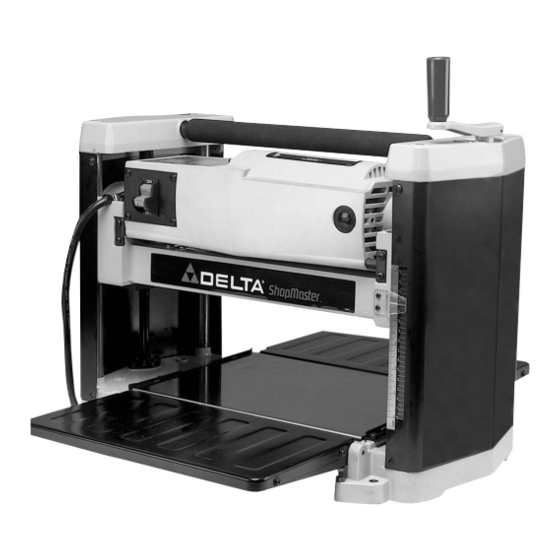
21029
12
1
/
" Portable Planer
2
(Model TP305)
PART NO. A07355 - 09-16-04
Copyright © 2004 Delta Machinery
To learn more about DELTA MACHINERY
ESPAÑOL: PÁGINA 17
RTD10000117AA
visit our website at: www.deltamachinery.com.
For Parts, Service, Warranty or other Assistance,
1-800-223-7278 (
1-800-463-3582).
please call
In Canada call
Advertisement
Table of Contents

Related Manuals for Delta TP305


Summary of Contents for Delta TP305
- Page 1 21029 " Portable Planer (Model TP305) PART NO. A07355 - 09-16-04 Copyright © 2004 Delta Machinery To learn more about DELTA MACHINERY ESPAÑOL: PÁGINA 17 RTD10000117AA visit our website at: www.deltamachinery.com. For Parts, Service, Warranty or other Assistance, 1-800-223-7278 ( 1-800-463-3582).
-
Page 2: Table Of Contents
NOT be modified and/or used for any application other than for which it was designed. If you have any questions relative to its application DO NOT use the product until you have written Delta Machinery and we have advised you. -
Page 3: Safety Guidelines
SAFETY GUIDELINES - DEFINITIONS It is important for you to read and understand this manual. The information it contains relates to protecting YOUR SAFETY and PREVENTING PROBLEMS. The symbols below are used to help you recognize this information. Indicates an imminently hazardous situation which, if not avoided, will result in death or serious injury. Indicates a potentially hazardous situation which, if not avoided, could result in death or serious injury. -
Page 4: General Safety Rules
13. USE RECOMMENDED ACCESSORIES. The use of accidents and injury. accessories and attachments not recommended by Delta may cause damage to the machine or injury to the 2. WEAR EYE PROTECTION. ALWAYS USE SAFETY user. GLASSES. Also use face or dust mask if cutting operation is dusty. -
Page 5: Additional Specific Safety Rules
ADDITIONAL SAFETY RULES FOR PLANERS FAILURE TO FOLLOW THESE RULES MAY RESULT IN SERIOUS INJURY. 14. ALLOW THE CUTTERHEAD TO REACH FULL SPEED DO NOT OPERATE THIS MACHINE until it is completely assembled and installed according to before feeding a workpiece. Changing speeds while planing can cause kickback. -
Page 6: Grounding Instructions
POWER CONNECTIONS A separate electrical circuit should be used for your machines. This circuit should not be less than #12 wire and should be protected with a 20 Amp time lag fuse. If an extension cord is used, use only 3-wire extension cords which have 3- prong grounding type plugs and matching receptacle which will accept the machine’s plug. -
Page 7: Extension Cords
Delta ShopMaster Model TP305 is a 12½" (317mm) Portable Planer. This planer can handle workpieces up to 12½" (317mm) wide and 6" (152mm) thick. The maximum depth of cut is 3/32" (2.4 mm). The TP305 features a powerful 15 amp, 120 volt motor, a two-knife cutterhead with double-edged reversible knives, knife-installation tool and wrench. -
Page 8: Assembly
UNPACKING AND CLEANING Carefully unpack the machine and all loose items from the shipping container(s). Remove the protective coating from all unpainted surfaces. This coating may be removed with a soft cloth moistened with kerosene (do not use acetone, gasoline or lacquer thinner for this purpose). After cleaning, cover the unpainted surfaces with a good quality household floor paste wax. -
Page 9: Operation
CUTTERHEAD GUARD 1. Attach the cutterhead guard (A) Fig. 7 to the planer by inserting the end of the guard over the top of the cutterhead. Place the slots in the cutterhead guard (C) over the tapped holes (B). 2. Fasten cutterhead guard (A) Fig. 8 to planer using two knobs, one of which is shown at (D). - Page 10 Fig. 10 Fig. 11 RAISING AND LOWERING HEAD ASSEMBLY The head assembly (A) Fig. 12A contains the cutterhead feed rollers, cutterhead guard and motor. Raising and lowering the head assembly controls the depth-of-cut on your planer. To raise or lower the head assembly, rotate the handle (D).
- Page 11 LEVELING EXTENSION TABLES The extension tables (A) and (G) Fig. 14 must be level with the planer table. To check the extension tables and adjust if necessary: 1. Place a straight edge (B) Fig. 14 on the planer table (E) with one end extending out over the infeed table (A).
-
Page 12: Replacing Knives
CARRYING HANDLE/STOCK TRANSFER BAR 1. Your planer is provided with a foam covered carrying handle (A) Fig. 17, located on top of the machine, for ease in transporting the planer. 2. The carrying handle (A) Fig. 18, also doubles as a stock transfer bar for transferring stock from the outfeed to infeed end of the machine. - Page 13 4. Insert knife transfer tool (G) Fig. 21, underneath center of knife. Lift the knife transfer tool up until knife (H) separates from pins (J) and pull out and remove knife as shown. NOTE: Knife transfer tool is magnetized, allowing it to attach to knife. Fig.
-
Page 14: Troubleshooting
OF THE KNIVES. TROUBLESHOOTING For assistance with your machine, visit our website at www.deltamachinery.com for a list of service centers or call the DELTA Machinery help line at 1-800-223-7278 (In Canada call 1-800-463-3582). MAINTENANCE KEEP MACHINE CLEAN Periodically blow out all air passages with dry compressed air. All plastic parts should be cleaned with a soft damp cloth. - Page 15 BRUSH INSPECTION AND REPLACEMENT DISCONNECT MACHINE FROM POWER SOURCE. Brush life varies. It depends on the load on the motor. Check the brushes after the first 50 hours of use for a new machine or after a new set of brushes has been installed.
-
Page 16: Service
Two Year Limited New Product Warranty Delta will repair or replace, at its expense and at its option, any new Delta machine, machine part, or machine accessory which in normal use has proven to be defective in workmanship or material, provided that the customer returns the product prepaid to a Delta factory service center or authorized service station with proof of purchase of the product within two years and provides Delta with reasonable opportunity to verify the alleged defect by inspection. -
Page 17: Español
Fax: (519) 767-4131 Fax: (604) 420-3522 Fax: (514) 336-3505 The following are trademarks of PORTER-CABLE • DELTA (Las siguientes son marcas registradas de PORTER-CABLE • DELTA S.A.) (Les marques suivantes sont des marques de fabriquant de la PORTER-CABLE • DELTA): Auto-Set ®...
Need help?
Do you have a question about the TP305 and is the answer not in the manual?
Questions and answers