
Related Manuals for Spring Air Systems Dynaflow


Summary of Contents for Spring Air Systems Dynaflow
- Page 1 Dynaflow Hood Installation and Maintenance Manual ___________________________ Spring Air Systems Inc., Oakville, Ontario Phone (905) 338-2999, Fax (905) 338-0179, info@springairsystems.com 2010 Revision 1.0...
-
Page 2: Table Of Contents
Dynaflow Installation and Maintenance Manual Table of Contents Introduction Spring Air Systems Hood Model Number Designations Dynaflow MB Hood Principle of Operation Three Fresh Air Boundary Regions Standard Dynaflow MB hood specification Dynaflow MJ Hood Principle of Operation Standard Dynaflow MJ hood specification Dynaflow Installation Arrangement “D”... -
Page 3: Introduction
Dynaflow Hood Installation and Maintenance Manual INTRODUCTION Thank you for selecting a SPRING AIR SYSTEMS INC. Dynaflow commercial kitchen exhaust hood. The Dynaflow hood is an innovative idea in commercial kitchen ventilator design that provides for the total kitchen comfort, particulate capture and energy efficiency. -
Page 4: Spring Air Systems Hood Model Number Designations
APPLIANCE Principle of Operation The Dynaflow design provides the lowest minimum exhaust. The Dynaflow hood exhaust volume is based on the appliances below the hood. It’s a simple adjustment to fine-tune your ventilator to provide excellent smoke capture with maximum grease extraction. -
Page 5: Three Fresh Air Boundary Regions
Comfort Tuning Blade (CTB) towards the appliances providing maximum exhaust air reduction. The second (2) Region discharges through a full length s/s angular panel located at the bottom front of the Dynaflow plenum. The fresh air is directed towards the chef to provide a more comfortable work environment in front of the hood. -
Page 6: Dynaflow Mj Hood Principle Of Operation
75F (13 to 24C). Direct the fresh air to separate diffusers surrounding the hood located in the finished ceiling. The diffusers must be located to eliminate short circuiting the exhaust and drafting. Consult with factory for recommended kitchen diffuser locations. If the hood is required to supply the fresh air directly refer to the Spring Air MB DYNAFLOW specification sheet 6.00... -
Page 7: Standard Dynaflow Mj Hood Specification
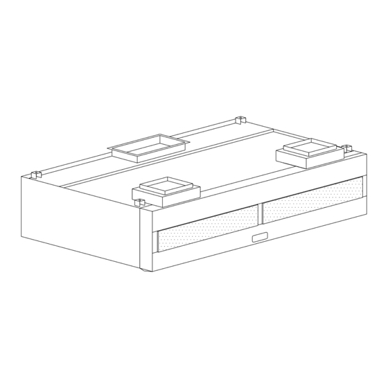
TYPICAL HANGER ROD BRACKET ISOMETRIC (FROM FRONT OF HOOD) APPLIANCE MJ BLOWER MJ BLOWER MJ DYNAFLOW PLAN VIEW MJ DYNAFLOW HANGER BRACKET SECTION VIEW Wall mounted Dynaflow model FN-B-MJ Hood in Plan and Section View showing hanger rod locations. Figure 7... - Page 8 Welding the Exhaust Duct to the Hood Exhaust Duct Collar A “FD” Dynaflow hood is supplied with an Exhaust duct collar fire damper in the hood exhaust duct collar. The fire damper must be closed before welding the hood duct collar to the exhaust duct. We recommend the exhaust duct be continuously welded to the exhaust duct collar of the hood per the current edition of the NFPA-96.
-
Page 9: Arrangement "D" Exhaust Fire Damper Assemblies
ARRANGEMENT “D” FIRE DAMPER ASSEMBLIES: Provide on all FD Dynaflow Hoods. (FN Hoods do not have a fire damper in the exhaust DAMPER BLADE duct collar) Description: DUCT FLANGE The section view of the exhaust fire damper to the right... - Page 10 Dampers up over 18” up to 32” long OVER 18" UP TO 32" FIRE DAMPER BLADE WIDTH FIRE DAMPER EXHAUST DUCT SPRING SHAFT COLLAR PERIMETER UNDERSIDE OF TOP OF HOOD Exhaust Fire Damper up to 18” to 32” long Figure 11 Dampers up over 32”...
-
Page 11: Adjusting The Fire Damper Blade Position
ADJUSTING THE DAMPER BLADE POSITION: The fire damper fusible links, springs and cable blocks are all accessible through the front on the hood. For filter hoods remove the baffle filters under the opening of the duct collar(s) of the hood. For dry extractors and cartridge remove the inserts under the opening of the duct collar(s) of the hood. -
Page 12: Grease Filter For Dynaflow Hoods
Grease Filters for Dynaflow Hoods VE- Stainless Steel Baffle Filters The exhaust air accelerates through two 90 EXHAUST AIR OUT OF BAFFLE FILTER degree turns within the baffle filters. The FILTER BAFFLES liquefied grease then drains down the vertical length of the baffles to the grease trough and into a grease cup. - Page 13 HE- High Grease Extraction Efficiency Cascade Filtration Cascade high efficiency hood filtration captures more grease than standard filters, reduce grease damage, the hassle and expense of duct cleaning, cost much less than other high performance filters, and have lower static pressure. Cascade is 270% more efficient (at 8 microns capture) then standard filters and removes 33% more grease than standard filters.
- Page 14 Flame Gard’s high rate of grease extraction is aided by our TEFLON® coated baffle. In the same manner that grease rolls off a TEFLON coated pan, it rolls down our baffles, out of the filter and into the hood’s remote collection cup. Because FlameGard’s filters retain only insignificant amounts of surface grease and do not load, you will have constancy of air flow throughout your operating day.
-
Page 15: Mj Blower Assembly For All Mj Hoods
MJ- Blower Assembly on Dynaflow MJ hoods. Every Dynaflow with MJ Perimeter Defense control has one or more MJ Blower assemblies mounted on the top of the MJ plenum. The MJ blower assembly consists of a double shafted 120V/1/60 AC motor with one tangential blower attached to each shaft. -
Page 16: Dynaflow Maintenance Schedule
DYNAFLOW MAINTENANCE SCHEDULE DAILY: 1. At the end of the cooking day wipe off the interior and exterior of the Dynaflow hood canopy and the underside of the grease trough with a damp cloth. Inspect the grease filters and clean if necessary. -
Page 17: Trouble Shooting And Cleaning
9. Dynaflow MB appliance air velocity too high. Adjust the MB Blade position to provide more fresh air out MB front and less to the appliances. 10. Dynaflow MB appliance air velocity too low. Adjust the MB Blade position to provide less fresh air out MB front and more to the appliances. -
Page 18: Measuring Exhaust Air Flow With Ve, He, Ec And Sa Filters
Measuring Exhaust Air Flow with VE, HE, EC, and SA Filters standard grease extraction efficiency Stainless steel baffles. High grease extraction Efficiency Cascade baffles for Enviro applications and reducing grease discharge from buildings. Easy Clean Teflon – standard grease extraction efficiency baffles for hot, heavy grease laden appliances. - Page 19 PITOT TUBE OR ANEMOMETER Spring Air Systems has factory calibrated the average filter slot velocity VS filter CFM. Measure the average bottom slot velocity of each filter and use Chart No. 2 to convert the slot velocity to total filter CFM.
- Page 20 VE/EC/SA STAINLESS STEEL FILTERS Average Slot Velocity vs CFM per Filter Filter Slot Filter Size VS CFM per Filter Velocity 16x16 20x16 20x20 20x25 (fpm) (CFM) (CFM) (CFM) (CFM) 1000 1100 1200 1300 1400 1012 1500 1084 1600 1156 1700 1228 1800 1041...
- Page 21 HE STAINLESS STEEL FILTERS Average Slot Velocity vs CFM per Filter Filter Slot Filter Size VS CFM per Filter Velocity 16x16 20x16 20x20 20x25 (fpm) (CFM) (CFM) (CFM) (CFM) 1000 1100 1200 1026 1300 1112 1400 1197 1500 1026 1283 1600 1095 1368...
-
Page 22: Measure Exhaust Air Flow With Ca Filters
Measuring Exhaust Air Flow with CA Cartridges medium efficiency cartridge with adjustable flow baffles. Setting the Cartridge Each cartridge is adjustable for various appliances. There are 6 settings. Closed, 1, 2, 3, 4, 5 and Open. The Open setting is for the heaviest appliance and the Closed setting is for the lightest appliances. - Page 23 Chart No. 4...
-
Page 24: Measuring Dynaflow Mb Supply
Measuring Dynaflow MB Supply Dynaflow type hood with Tri-Zone control System Each of the three regions must be measured to ensure proper hood operation. The Appliance Region, the MB Blade Chef Region and the Kitchen Ambient MB HOOD CANOPY Region as shown in the schematic... -
Page 25: Adjusting The Mb Blade To Change Velocity At The Appliance Region
Hood Appliances VS Appliance Region Face Velocity Discharge Velocity (fpm) Hood Length FRONT SIDE APPLIANCES (ft) FLOW Set point Set point Heavy 9 - 14 6 - 9 4 - 6 Up to 4 Medium/Light 9 - 14 6 - 9 4 - 6 Up to 4 Chart No.5... -
Page 26: Measuring The Supply Discharge Velocity From The Mb Blade
D. Measuring the Supply Discharge velocity from the MB Blade MB Blade Discharge perforated plate There are two sizes of MB Blade Discharge Grills. MB Blade Perforated Discharge MBFront41x06 with a perforated discharge dimension of 41.5” wide x 6” high. The face area is 1.38sq feet MBFront33x06 with a perforated discharge dimension of 33”... -
Page 27: Measuring Dynaflow Mj Plenum Air
Measuring Dynaflow MJ Plenum Air Dynaflow type hood with Perimeter Defense control System MESH FILTERS MESH FILTERS MJ BLOWER MJ BLOWER RHEOSTAT RHEOSTAT FIRE DAMPER FIRE DAMPER SIDEFLOW FRONTFLOW MJ PLENUM MJ PLENUM HOOD CANOPY HOOD CANOPY END VIEW FRONT RIGHT VIEW... -
Page 28: Adjusting The Mj Blower To Change The Appliance Region Velocity
Discharge Velocity (fpm) Hood FRONT SIDE APPLIANCES Length FLOW (ft) Set point Set point 9 - 14 Heavy Appliances 6 - 9 4 - 6 Up to 4 9 - 14 Medium and Light Appliances 6 - 9 4 - 6 Up to 4 Chart No.7 B.
Need help?
Do you have a question about the Dynaflow and is the answer not in the manual?
Questions and answers