Table of Contents
Advertisement
Quick Links
Advertisement
Table of Contents

Subscribe to Our Youtube Channel
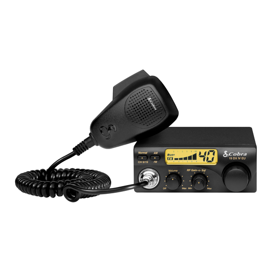
Summary of Contents for Cobra CB 19 DX4 EU
-
Page 2: Specifications
Model No: 19 DX4 EU Cobra Rev.: A SPECIFICATIONS 1. GENERAL Channels………………………...……………………......EU CH AM/FM 1W/4W Frequency Range………………………………...………………………..26.565 to 27.99125 MHz Temperature Range……………………..…………………….………..…-10°C / +55°C Input Voltage………………………………...…………………………..13.2VDC ±15% Size………………………………………….……………..………190(L) X 45(H) X 120(D) mm Weight……………………………………………………..………………..Approx. 0.945 kg 2. RECEIVER Receiving System………………………………………………………...Super Heterodyne Frequency…………………………………………….…1... - Page 3 Model No: 19 DX4 EU Cobra Rev.: A OPERATION INSTRUCTIONS Having properly installed your batteries and hooked-up the antenna, you are now ready to operate your radio for optimum reception and voice transmission. Turn the power “ON” with ON/OFF switch.
-
Page 4: Theory Of Operations
Model No: 19 DX4 EU Cobra Rev.: A THEORY OF OPERATIONS TRANSMITTER A. RF Amplification The output of double AMP Q14 is fed through tuning IFT L8 to the base of pre driver AMP Q15. The output is then supplied through tuning circuit L9 to RF driver AMP Q16. The output of Q16 is supplied with tuning circuit L10 and C116,C67,C95 and goes to the base of final RF AMP Q17. -
Page 5: Troubleshooting Hints
Model No: 19 DX4 EU Cobra Rev.: A TROUBLESHOOTING HINTS Symptom Possible Causes Remedy Suggestions • Defective power switch Unit does not work • Blown fuse • Replace defective components at all • Broken DC power cord • Defective components •... -
Page 6: Test Setup
Model No: 19 DX4 EU Cobra Rev.: A TEST SETUP A. TX test setup: Filter with Spectrum Power attenuation Analyzer Supply Modulation Wattmeter Radio Meter U.U.T. Oscilloscope Frequency Audio Gen. Counter B. RX test setup: SINAD Meter RF Signal Power... -
Page 7: Alignment Procedure
Model No: 19 DX4 EU Cobra Rev.: A ALIGNMENT PROCEDURE VCO Voltage 1. Test point TP1 connect to the multi-meter,set UUT enter test mode. Use channel “UP” key to select CH41 (26.565MHz) of DE Band in FM mode. 2. Adjust IFT L17 for 1.0 ± 0.1V on the Multi-meter read, and then checking CH40 (27.99125MHz) of UK Band should be less than 3.8V. - Page 8 Model No: 19 DX4 EU Cobra Rev.: A TX Alignment TX Output Power and Frequency 1. UUT set to FM EU CH19, Antenna connect to the RF power-meter input terminal. 2. Set UUT to TX mode, adjust the IFT L8 and L9 for TX power output maximum, and then adjust the RV4 check the output TX power for 3.5W.
-
Page 9: Voltage Chart
Model No: 19 DX4 EU Cobra Rev.: A VOLTAGE CHART Transistor Transistor 13.2 13.0 8.10 Diode Diode 10.6 12.8 13.2 Page: 9 / 13... - Page 10 Model No: 19 DX4 EU Cobra Rev.: A 13.2 13.2 IC6 PIN 13.2 13.2 Page: 10 / 13...
- Page 11 Model No: 19 DX4 EU Cobra Rev.: A Page: 11 / 13...


Need help?
Do you have a question about the CB 19 DX4 EU and is the answer not in the manual?
Questions and answers