Table of Contents

Related Manuals for Ferroli Modena 102


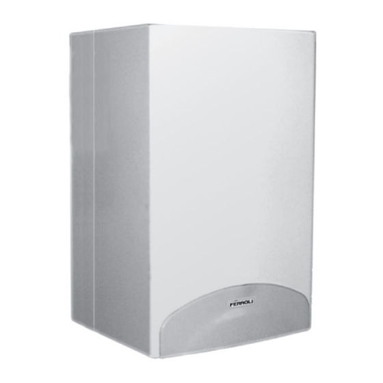
Summary of Contents for Ferroli Modena 102
- Page 1 Copper Wall-Mounted Combination, Gas Fired Boiler for Central Heating and Domestic Hot Water Production, Fan Assisted, Room Sealed Compartment, Electronic Flame Ignition and Control I S A , SER ICI G A D USER I S RUC I G.C. 4 - 6 - 4...
- Page 2 You can check the installer's CORGI registration by calling CORGI on 01256 372300". Ferroli is a member of the enchmark initiative and fully supports the aims of the programme. enchmark has been introduced to improve the standards of installation and commissioning of central heating...
- Page 3 1.01 Introduction Modena 102 is d fin d as a “room s al d” combination boil r, all air r quir d for combustion is tak n from outsid t room in w ic it is install d. It is a n w ig p rformanc gas fir d...
- Page 4 2.01 Technical information Modena 102 boilers are central heating and domestic hot water heat generators and are produced as standard to function with natural gas or liquid petrolium gas converted. Distance between connections Fig. 1 Bottom view Top view 1 - 3/ " central heating fl ow outlet - 1/ "...
- Page 5 Domestic hot Domestic hot Heat input water heat Boiler water Heat output water circuit input contents MODEL contents Gross Litres Litres Modena 102 30.0 12.7 33.1 14.5 30.0 Max. working Max. Connections Expansion vessel pressure working central pressure hot MODEL...
- Page 6 2.02 Boiler mai om o e t 2.03 Boiler water fl ow diagram FLUE FERROLI GRUNDFOS 85 44 C.H. D.H.W. D.H.W. C.H. omest c ot ater o or se e as anal ser temperat re sensor Room sealed compartment A r press re s tc...
- Page 7 entra heatin ad ustment not normally re uired To ad ust boiler heat input thus also regulating heat output to the central heating water simply ad ust the main burner via the electronic control board fi g. 5 and see paragraph 5.0 page The diagrams indicate the variation in heat output to the water as burner wor ing pressure is varied.
- Page 8 SAFETY VALVE SETTING (bar) SIZING OF ADDITIONAL EXPANSION VESSELS: VESSEL CHARGE Deduct from the value given in the table the 10 PRESSURE (bar) litre vessel supplied. INITIAL SYSTEM PRESSURE (bar) TOTAL WATER CONTENT f SYSTEM EXPANSION VESSEL VOLUME ( r ) ill .
- Page 9 I . If in dou t ad ice should e sou ht fro the ocal upplier. Location of Boiler he installation of the Modena 102 e on a suita le non co usti le load earin...
- Page 10 Water System Note - the boiler is designed for sealed systems only and must NOT be used on open vented systems. Central Heating Detailed recommendations are given in BS6798, BS5449, BS6700 and CP342 Part 2. Pipework not forming part of the useful heating suface should be insulated to prevent any heat losses or possible freezing (i.e. in roof spaces or ventilated underfl...
-
Page 11: Terminal Position
5 min. 5 min. 50 mm CLEARANCES: * 600mm minimum clearance for servi- 600* min. cing access Terminal Position D, E inim m imensions o e terminal ositions Balanced flues room Open flues sealed Dimensions Terminal position (kW input expressed in net) Natural Fanned Natural... - Page 12 3.01 Drilling Template (Top Flue Application) Select suitable mounting position for boiler, using the template mark fl ue outlet and boiler mounting points. Drill two 10mm holes 90mm deep to accept the wall plugs, fi t wall plugs. Fit two special wall plugs on the wall as described in the fi...
- Page 13 Calculate the total fl ow resistance of the air and fl ue pipes in metres (cap. 3.04. ) utilise the table shown below to choose the more suitable restrictor for the fl ow resistance calculated RESTRICTOR FOR TWO PIPE SYSTEM ON MODENA 102 Total flow resistance restrictor of flue system size...
- Page 14 3.03 Top Outlet Concentric Flue Connection 3.03.1 Vertical concentric connection ertical connector can be supplied for ertical discharge with concentric pipes. The si ple ounting and use of double lip gas ets Concentric at the oints a es this an e tre el eas and safe Vertical option.
- Page 15 125 mm concentric Maximum flue lenght permissible Vertical Horizontal* Vertical Horizontal* Modena 102 or horizontal lueing the re uction or a liance en or turret are alrea inclu e . Reduction for bend 100 mm concentric bend 90° 100 mm concentric bend 45°...
- Page 16 Ø80. Insert blanking plate 2 in remaining air intake. A varied selection of accessories for two pipe systems are available from Ferroli (ref. to page 17). Before installing your system please check via calculation table at 3.04.2 you are not exceeding the maximum permissible length for the appliance.
- Page 17 3.04.2 (continued) REDUCTION REDUCTION Tab. 1 - Pipes and FLUE FLUE fi ttings reduction table Description Dscription Male-female flue/Air pipe Horizontal 1 m - Ø 80 flue terminal Ø 80 mm Female-female bend Air intake 45° Ø 80 m terminal Ø...
- Page 18 For further accessories please refer to: "Flue system manual for room sealed boiler" Example of calculation for wall inlet/outlet with 2 pipe system maximum total fl ue length: 50 metres Attention: 13 m 13 m Remove the fl ue diaphragm. The fl...
- Page 19 3.05 Connecting the central heating and domestic hot water circuits Connect to the relevant connections as indicated in fi g. 1. Connect the pressure relief valve discharge pipe (15mm) to the outside of the building, where possible over a drain. The discharge must be such that it will not be hazardous to occupants and passers-by or cause damage to external electric components or wiring.
- Page 20 When the boiler is connected to an electricity main, it is essential TO OBSERVE CORRECT POLARITIES (LIVE: brown cable, NEUTRAL: blue cable, EARTH: yellow-green cable) All wiring must con orm to current I E E regulations : I the power supply cable has to be replaced, use “0 75mm (24/0 20) heat resisting cable only to BS6500 with a maximum external diameter o 8 mm When connecting a room thermostat or external timer, do not lin the power supply o these de ices to the switching contacts The switch contacts must be oltage ree Any mains powered de ices must utilise...
- Page 21 3.13 Time cloc fi in (optional) - Remove outer case by removing two securing screws from the rear bottom corners and lift off. - Remove screw securing facia panel and swing facia panel down. - Remove rear cover from facia. - Remove clock blanking plate from the boiler facia panel.
- Page 22 4.01 Checks to be carried out before starting up for the fi rst time When starting the boiler up for the fi rst time check: • that the gate valves between the boiler and central heating system are open; • that the central heating system is fi lled and vented; •...
- Page 23 • Chec that the domestic hot water flow and T correspond to the table. o not rely on empirical measurements. Temperature should be measured using thermometers as near as possible to the boiler, in mind the heat loss from the pipes. •...
- Page 24 5.09 Gas con ersion The followin adjustment and conversion operations must be carried out by competent personnel FERROLI Limited accepts no liability for dama e to property or personal injury resultin from tamperin with the boiler by unauthorised persons To convert the boiler from Nat Gas to LPG and vice versa, the main burner injectors must...
- Page 25 The following operations must be carried out by Corgi registered engineers only. 6.01 Annual Servicing The following should be checked at least once a year: • Water pressure in the central heating system when cold should be about 1 bar. If this is not the case, bring it back to this value.
- Page 26 16. Clean heat exchanger with a soft brush. 17. Re-assemble baffl e, fl ue hood and fan assembly, secure with screws previously removed. 18. Refi t burner assembly and burner rail. 19. Reconnect ignition and fl ame rectifi cation leads. 20.
- Page 27 7.01 Initial procedure a) The boiler is cold, electricity supply is isolated, and the gas supply is turned off at the inlet of the boiler b) For replacement of parts where water connections are broken, it will be necessary to isolate and drain either or both the central heating or domestic hot water circuits of the boiler.
- Page 28 7.05 Gas valve • Isolate as and electricity supplies • Remove outer case two screws bottom rear corners • Remove the two securin screws and lower control panel • Disconnect electrical connections from valve "A" • Disconnect plastic tube "C" •...
- Page 29 7.10 Removal of burner (fi g. 30) • Isolate gas and electricity supplies • Remove outer case (two screws bottom rear corners) • Remove room sealed cover • Disconnect ignition and fl ame rectifi cation leads "A" • undo gas rail union "B" •...
- Page 30 7.14 Spark or fl ame detection electrode • Isolate as and electricity supply • Remove outer case two screws bottom rear corners • Open room sealed compartment and combustion chamber • Identify electrode from • Unplu electrical connection "A" from sensin electrode •...
- Page 31 7.16 Pump Replacement of pump head • Isolate electricity and flow and return pipes • Remove casin two screws bottom rear corners • Remove the two securin screws and lower control panel • Release pressure from boiler via pressure relief valve •...
- Page 32 Before beginning any fault fi nding ensure that gas, water and electricity are available. WARNING: DO NOT link any terminals on block X10 or X11 as this will damage the PCB beyond repair. 8.01 Operating Sequence ith the power established the boiler is in its stand by mode i. e. power on but no demand. The operational se uence for C.
- Page 33 In order, the fi ve lights indicate: oiler n Indicate oiler h t do n arning o estic ot ater circ it entral eating stand lashing ight entral eating circ it er anent ight Ins fi cient ress re in entral eating lashing ight lectric o er s er anent ight...
- Page 34 8.04 Temperature sensors (thermistors) Identical, but individual, negative temperature co-effi cient (NTC) thermistors are fi tted in the C.H. and D.H.W. outlets from the heat exchanger. As the water temperature increases the resistance in the thermistor decreases. This causes the PCB to reduce the voltage to the modureg, in turn reducing the burner pressure. The wiring for each thermistor is colour coded red for C.H.
- Page 35 8.10 General test and fault fi nding Chart 1 Check electrical supply - C.H. water pressure and frost protection Chek the following carefully before starting • Gas supply is turned on, is adequate and purged • Electricity supply is turned on •...
- Page 36 Chart 2 Check Domestic Hot Water operation Open DHW taps DHW flow rate at least 2,5 litre/min? Check cold water inlet pressure Check and if necessary Is LED3 on? replace DHW Sensor Check if water filter is clean Check and if necessary replace Flow Sensor Is LED4 flashing? Check and if necessary...
- Page 37 Chart 4 Check fan/fl ue gas system Does fan run? Is air pressure switch activated? Is relay RY100 switch ON? Go to chart 5 Differential air pressure across the air pressure Go to charts 2-3 switch is greater than 180 Pascal? Check and if necessary replace Is 230V present across...
- Page 38 Chart 6 Check ignition system Is LED1 light on? Is LED2 on Does sparking start without at burner? the boiler sparking Does burner light? Go to chart 5 Re-check air pressure switch Check and if necessary Is LED2 on replace safety thermostat after 10 seconds? Check electrodes and Check and if necessary...
- Page 39 9.01 Ma n components layout on electron c boar s Potent ometer a ustment P1 = entral heating ow te erature ad ust ent P2 = Do esti hot water te erature ad ust ent P3 = entral heating ow out ut ad ust ent = gnition gas ressure ad ust ent ini u ad ust ent ressure...
- Page 40 9.02 General wiring diagram...
- Page 41 KEY DESCRIPTION Switch OFF/ON/RESET Burner on indicator Central heating flow temperature regulation Boiler shut down warning D.H.W. temperature Domestic hot water circuit on regulation Central heating stand-by (Flashing light) Water pressure gauge Central heating circuit on (Permanent light) Insufficient pressure in central heating system (Flashing light) Time clock (option) Electric power supply (Permanent light) The boiler is designed for use with two types of gas: natural gas NG or propane (LPG).
- Page 42 In the e ent of the red lockout light ( ) coming on the on off reset switch (A) should be turned clockwise against the spring tension to the reset position and released (this will put the boiler into three minute delay if in the heating mode).
- Page 43 A 24 hour time clock is fi tted to the boiler to control the central heating, this will come into operation when the selector switch is turned to the position marked “heating timed and hot water”. lide switch: set clock auto set programme AUTO AUTO ispla .
- Page 44 Should ou re uire help ith an diffi culties call our Technical Ser ice Helpline on 08707 282 885 Phone nu Installer Ser ice En ineer ALL SPECIFICATIONS SUBJECT TO CHANGE Please note - to avoid incurring unnecessary expense, in the event of a boiler shut down, check this in not caused by lack of electricity supply, gas supply or low water pressure before calling our Customer Service Helpline.
Need help?
Do you have a question about the Modena 102 and is the answer not in the manual?
Questions and answers