Aethra Vega X3 User Manual
Camera
Hide thumbs
Also See for Vega X3:
- Technical specifications (2 pages) ,
- Use and installation manual (99 pages) ,
- Getting started (64 pages)
Table of Contents
Advertisement
Quick Links
Advertisement
Table of Contents

Related Manuals for Aethra Vega X3


Summary of Contents for Aethra Vega X3
- Page 1 Vega X3 User manual...
- Page 2 ® Thank you for choosing a AETHRA SpA. Product. Inside you will find useful information to help you get the most out of the Aethra product. The information contained in this document is the property of Aethra SpA., it is subject to change without notice and it shall in no way be binding for Aethra SpA ©...
-
Page 3: Table Of Contents
LASS OMPLIANCE CE MARK ..........................8 ....................9 CUSTOMER INFORMATION ABOUT THIS MANUAL ......................10 ABOUT GRAPHIC USER INTERFACE (GUI) ..............11 ABOUT VEGA X3 ........................12 ........................... 12 RELIMINARY ......................12 ENERAL INTRODUCTION ......................13 EATURES AT A LANCE ...................... - Page 4 ................. 28 OW TO MAKE A CALL FROM HONEBOOK ......................... 29 UDIO VIDEO CALLS ..............30 ESELECT AN NCOMING OR UTGOING TCS-4 M ....................... 30 IDEO ..........................31 UDIO CALL ......................31 ECURE ONNECTIONS ......................31 OW TO RECEIVE A CALL ) ....................
- Page 5 Monitors ..........................48 Settings ..........................48 PIP-PaP..........................51 Plasma/LCD ........................53 Viewing modes......................53 Data Channels........................58 .......................... 59 NSTALLATION Terminal Settings......................... 59 Network interfaces....................... 60 IP configuration ....................... 60 IP Configuration ......................60 H323 Settings ......................62 SIP Settings ......................... 62 Services (Web-Telnet, SNMP, Streaming) ..............
- Page 6 Hardware ..........................87 Software Versions ....................... 87 CONNECTING A PERSONAL COMPUTER ............... 88 LAN..............88 ONNECTING A TO THE YSTEM WITHOUT LAN ..............88 ONNECTING TO THE YSTEM VIA A IN A CONNECTING TO THE “MODULE INTERFACE” ............89 X LINE NETWORK ADAPTER ( ) ................
-
Page 7: Safety Rules
AFETY ULES CAUTION: do not touch the internal parts of the device (and/or of the mains adapter). DEVICE IN CLASS I Always connect to a grounded socket. CAUTION: if objects or liquids leak into the device, disconnect the power supply cable IMMEDIATELY. CAUTION: for the operator's safety, only use the Have it checked by an authorized technician before mains adapter that has been provided with the... -
Page 8: Safety Rules For Batteries
CE MARK with your skin or garments, wash the area immediately with water. If it comes into contact Aethra S.p.A. hereby declares that this device with your eyes, wash immediately with plenty of complies with essential requirements and other water and contact either a doctor or the nearest relevant notes of R&TTE Directive 1999/5/EC. -
Page 9: Fcc Customer Information
If trouble is experienced with this equipment, for repair or warranty information, please contact Aethra Inc, 155 South Miami Avenue, Suite 300, Miami, FL 33130, USA Tel: +1 305 375 0010. If the equipment is causing harm to the telephone network, the telephone company may request that you disconnect the equipment until the problem is resolved. -
Page 10: About This Manual
About this manual Used symbols and syntax: Symbol related information must be followed very carefully. Nota _ Associated instructions give useful information. _ Instructions in a enumerated list must be accomplished following the reported order. _ The list preceded by capital letters denotes: possible choices at a main level. -
Page 11: About Graphic User Interface (Gui)
About graphic user interface (GUI) All system configurations and functionalities can be activated inside GUI (Graphical User Interface) shown on the monitor. Main elements inside a MENU page: Home page PAGE – any page inside graphic user interface (GUI). HOME PAGE – main GUI page; Icons Video window from here you can access all... -
Page 12: About Vega X3
About Vega X3 Preliminary ATTENTION !!! You have to insert SW licence enabling code (AETHRA SOFTWARE LICENCE KEY) By pressing the “START” button, you’ll have 12 hours working time (switched on system time): at the end system will stop, waiting for the enabling code (see “Licences”... -
Page 13: Features At A Glance
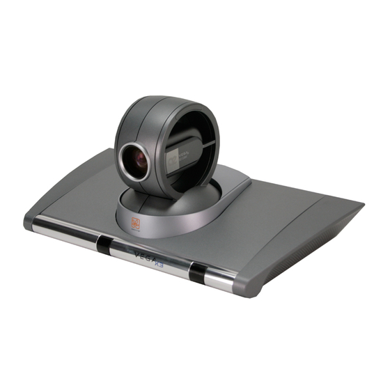
T.120 for multimedia. Full-duplex audio with echo cancellation. Automatic Noise Suppression. Remote diagnostics and management. Web streaming function. Vega X3 components Main components of the Vega X3 are: H.320/H323 system Integrated camera Aethra High-Band POD Power supply with cable Infrared remote control... -
Page 14: Remote Control
Remote control Note In order to avoid un-desired controls reaching other systems, user can modify transmission power from 2mt to 20mt (default) by means of a switch in the battery space: Move both the Switches to- position 20mt Move both the Switches to - (1,2) position Remote control Remote control controls all system functions (see “Remote control”... -
Page 15: Remote Control Keys
Remote control keys Description function ON/OFF Key It turns on and off the system. It puts the system in “screen saver” mode. It restarts the system from the “screen saver” mode. By pressing the key results in opening a window of notice: - Turn off the system. - Page 16 HOME Key Comes back to the Home interface page, saving any parameter eventually modified. SELF Key Activates/deactivates selfview. HELP Key Activates/deactivates on line help. During connections activates “Diagnostics”. (- / +) Keys ZOOM: sets the camera zoom. Auto Key Activates/deactivates the autotracking function (NOT available). (- / +) Keys VOL: sets the audio level.
-
Page 17: Remote Control Alpha-Numeric Symbols To Keys Association
CAMERA Key Selects a video input. Usable as camera choice shortcut. (see “Audio-Video-Data chapter/Customize cameras”) MEMO-PRESET Key Saves the camera presets. SEL-PRESET Key Selects the camera presets. Alphanumeric Keys It allows letters and numbers insertion. (See the chart) Remote control alpha-numeric symbols to keys association SYMBOLS └─┘... -
Page 18: Cabling Scheme
Cabling Scheme In the scheme below, examples of possible connections are shown. -
Page 19: Videoconference Tips
Videoconference tips Tips to improve a virtual meeting, to optimize audio-video transmission and reception, and to fully enjoy all videoconference benefits. Optimal Meetings • Before starting a videoconference be sure that all you need is ready: addresses or numbers to call, lighting, microphones. -
Page 20: System Positioning And Installation
Connection to main power supply should only be performed after complete parts assembly. Place the System in the desired location, and connect the follow equipments: Connect the “Aethra High Band POD” (see “Cabling Scheme”, cable Connect System Audio/Video Outputs to main monitor (see “Cabling Scheme”, cable... -
Page 21: Connecting The Aethra Pod
High Band POD Connect the High Band POD output to the rear panel of the System. In case a second High Band POD is used: connect second POD output to first POD input. NOTE Max two (2) Aethra Pods can be used. -
Page 22: Operation And Use
This section of the manual explains the basic functionality of the System. It is assumed that the system is correctly installed. First time equipment is switched on ATTENTION !!! You have to insert SW licence enabling code (AETHRA SOFTWARE LICENCE KEY) First time the system is switched on, you need to: insert the licence code;... -
Page 23: Location Parameters Setting
Location parameters setting Once the license code has been inserted, the Location page is shown. To ensure correct system operation, following parameters should be set: Country Video Standard Cameras Frequency... -
Page 24: Menu Structure
Menu structure... -
Page 26: Home Page
Home Page Once switched on, the System shows main user interface, the “Home Page”; from here you can place a Call, modify system Settings, and control system status by means of Status Bar. Video window - to Active icons to place a control local camera call. -
Page 27: How To Make A Call
How to make a call Once the System is on, the main user interface will display the “Home Page”. A call can be made in three different ways: From the Phonebook – see § “How to make a call from Phonebook”. Audio/Video –... -
Page 28: How To Make A Call From Phonebook
How to make a call from Phonebook To enable the quick selection of a number to call, a phonebook is available to store data about terminals that are frequently called. To call one of these numbers, users need only select the entry in a list. arrow From the , using the... -
Page 29: Audio-Video Calls
Audio-video calls From the , select the VIDEO icon. The same function can be achieved by CALL pressing the key on the remote control. You will enter the following page: To complete the video call, please follow these steps: Select the call type from the dropdown menu (ISDN, IP-H323, IP-SIP, MCU, MCU ISDN, MCU IP). -
Page 30: To Reselect An Incoming Or Outgoing Call
To Reselect an Incoming or Outgoing Call Incoming calls are indicated with a green arrow while outgoing ones are indicated with a one. A cyclic buffer of 60 numbers is available to store calls. CALL To reselect a called number press the remote control key twice. -
Page 31: Audio Call
Audio call If you would like to make an audio-only call (using the System like a normal telephone), select the AUDIO icon from the To complete the audio call, follow these steps: Select the type of call (ISDN, IP-H323, IP-SIP) from the drop-down menu. -
Page 32: Dual Video Mode (Option)
Dual Video Mode (option) Dual Video Connection You can create a Dual Video connection to send two video streams originating from different sources. This is feasible on the condition that the remote terminal supports Dual Video. Dual Video transmissions can be initiated by either the Audio-Video calling or called terminal. -
Page 33: Dual Video Disconnection
Dual Video Disconnection To disconnect Dual Video only: Dual Press the key on the remote control. Move to the icon Yes and press Note Disconnect To disconnect the whole Videoconference press the key on the remote control. -
Page 34: Phonebook
Phonebook System allows use of either a “local” phonebook or a phone book on a “remote server” (LDAP H.350 protocol). You can select desired phonebook by means of drop-down menu: Local for local phonebook Remote server identifier for remote server phonebook Entering Names in the Phonebook From the , go to the PHONEBOOK icon and press... -
Page 35: Modifying And Erasing Phonebook Entries
Modifying and Erasing Phonebook Entries To modify a phonebook entry: Select the desired entry and press OK icon and press OK again Move to the Modify Enter modifications and save them To erase an entry in the phonebook: Select the desired entry and press OK. Move to the icon and press OK (the system will ask you to confirm deletion). -
Page 36: Video Input Management
Video Input Management It is possible to manage different video inputs by selecting them using the remote Camera Yellow Camera control keys . The function keys – , can be configured to be associated with any available video input. Possible choices include: Room camera XGA/DVI-I video input Whatever video peripheral with composite signal (e.g. -
Page 37: Video Privacy
Video Privacy In connection PRIVACY To activate the Video Privacy function, press the key on the remote control. Local video will no longer be transmitted. The icon will appear in the video window indicating that the remote terminal is no longer receiving video from local terminal. Not in connection Activates/Deactivates: –... -
Page 38: System Configuration - Settings
System Configuration - Settings This section describes the procedures to properly configure the System. Note that some configuration parameters can be modified only when no connection is active. User preferences From the select: OME PAGE ETTINGS ETTINGS The following page will be displayed: From here you can access the following submenus: Control Panel Call-Answer mode... -
Page 39: Control Panel
Show warnings If activated, allows visualization of “Bonding Recovery” messages. Show logo when in a call Enables/disables logo display during a call. Logo is customizable—default is Aethra S.p.A. Disable still picture disable transmission/receiving of “still images”. Send received still to TFTP server... -
Page 40: Remote Control
Remote control Numeric only remote control Enable\Disable alphabetical digits only on the remote control. ID code (1-99) In order to control more systems with only one remote control, you can assign to each system a numeric code (01 to 99), and then consequently set the remote control. A) To configure the system: Select the code box. -
Page 41: Call-Answer Mode
Call-Answer mode General This menu contains the following configuration settings: Mute selected, at the start-up and after each disconnection system will not transmit audio, an icon will be displayed in the local and remote terminals. Do Not Disturb selected, at the start-up and after each disconnection system will not accept incoming calls, an icon will be displayed in the local terminal. -
Page 42: H.320
H.320 This menu contains the following configuration settings: Audio Number = Video Number In a non-aggregated ISDN call, the audio number may be different from the video number. If this checkbox is not selected, the System will request the video number and offer by default the same number as the one used by audio. -
Page 43: Display Status Bar And Transparency
Display Status Bar and Transparency • ENABLE STATUS BAR Allows you to personalize the System graphical interface, choosing whether you want the status bar to be present and, if so, what information should be displayed on it. Status bar information: Date &... -
Page 44: Audio - Video - Data
Audio – Video – Data From the select: ETTINGS UDIO IDEO The following page will be displayed: You can access the following submenus: Audio Video Quality Cameras Monitor Data channel... -
Page 45: Audio
Audio You can access the following submenus: Inputs Processing Outputs and adjust the ringing and sound volume. Volume for Ringing and Sound. For adjust the ringing and sound volume, follow these steps: Select AUDIO or RINGING from the Volume dropdown menu. arrow Use the remote control keys to move the Volume slider control. -
Page 46: Video Quality
This allows the configuration of the following parameters: Video Quality-Speed: • To balance between sharpness and dynamic nature of video images. Aethra Error Strategy: • Set the number of allowed line errors before video is frozen: “Min Fluency”: stop video at the first occurred error, “Max Fluency”: never stop video and allow errors through. -
Page 47: Cameras
Cameras This menu allows you to: Settings Customize Driver Settings • Enable/disable the of the local camera. remote control • Enable/disable the Bring Back to place button of the local camera. The last position of the Main camera, in case of stand-by of the set top, will be memorized for being restored to wake up again. -
Page 48: Monitors
Monitors In this page is possible to configure system video outputs. You can access three menus: Settings PIP-PaP Plasma/Lcd Settings In this page you can set following system parameters: Monitors Number Monitor Menu Video outputs Dropdown Menu (default setting: Automatic). Monitors Number Following table shows all available configurations: Dropdown menu... - Page 49 Dropdown Menu (default setting: Automatic). Monitor Menu In case the TV1+ HighDefTV configuration has been chosen, so to have two monitors connected to the system, is possible to choose where to see GUI (Graphical user interface). Available configurations are: GUI set by the system Automatic GUI always on TV1 GUI always on XGA/DVI-I...
- Page 50 Available XGA/DVI-I output resolutions are: XGA resolutions HDTV resolutions 1280x768 720p 1024x768 576p 800x600 480p 640x480 Note: DVI-I interface includes digital and analog signals (VGA, XGA, etc.) The following example show the adjustment of 4:3 video in 16:9 video.
-
Page 51: Pip-Pap
PIP-PaP In this page is possible to select “Multi Imagine” system functionalities: PIP: Picture In Picture Allows to see two overlapped images in one monitor, that is remote image in full-screen format, an local image in a smaller overlapped window. Self By means of remote control key you can switch windows content. - Page 52 Multi Image Type By selecting AUTO a mixed PIP and PaP function is enabled. By means of remote control “PIP” key you can switch between PIP and PaP. By selecting PIP , PIP function is enabled. By selecting PaP , PaP function is enabled. Multi image type must be enabled separately for TV and HighDefTV monitor.
-
Page 53: Plasma/Lcd
Plasma/LCD Select plasma, type of monitor and viewing modality. Note: The follows instructions refers to “Pioneer” monitors. Please carefully check XGA, Y/C and RS232C/DEBUG (null modem cable) connections between plasma and System. a) In the field, set the plasma model Type b) In the field, select the number of connected plasma monitors... - Page 54 Automatic MultiScreen Selecting this mode, the system shows two side-by-side equal-sized pictures: graphics relating to system management will appear on the right, whereas motion video will appear on the left. Once connected, an XGA remote signal automatically changes the viewing mode to BigLittleScreen mode;...
- Page 55 c) Connected system that receives a remote XGA image (with 50” Pioneer plasma, you’ll obtain two 4:3 images, a big one (42”) with 1024 x 768 XGA resolution image and a small one (11”)). d) Connected system with remote XGA image, while local user looks at the menu. e) Connected system with remote XGA image, in DualVideo XGA mode.
- Page 56 Fixed MultiScreen Selecting this mode causes the system to display two side-by-side, equally-sized frames. Graphics relating to system management will appear on the right, while remote video (or XGA) appears on the left. Automatic BigLittleScreen If this mode is selected, the system will show two video outputs in different-sized frames. The larger frame on the left will show the graphics relating to system management, while the video stream will appear in the smaller frame on the right.
- Page 57 c) Connected system that receives an XGA image. d) Connected system while user browses the menu. e) Connected system that receive an XGA image on Dual Video XGA mode.
-
Page 58: Data Channels
Data Channels From the select: –V –D ETTINGS UDIO IDEO HANNELS In this menu you can: Enable or disable transmission. Data Select the Serial Rate Enable or disable function (if activated allows AT commands usage). Modem • Activate/deactivate the RS232 control Choose the (H.320 only). -
Page 59: Installation
Installation From the select: ETTINGS NSTALLATION You will be prompted for a password. The password is required to avoid accidental modifications and changes to settings. Terminal Settings From the select: ETTINGS NSTALLATION ERMINAL ETTINGS In this section you can configure terminal settings for various network interfaces. For each interface it is possible to set, if present: The maximum data Rate for a call. -
Page 60: Network Interfaces
Network interfaces From the select: ETTINGS NSTALLATION ETWORK NTERFACES In this section you can choose and configure the system’s network interfaces. For each interface, it is possible to set some parameters. IP configuration From the select: / IP ETTINGS NSTALLATION ETWORK NTERFACES The following page will be displayed:... - Page 61 (in Kbps). These limits can be different in transmission and reception, a very useful function on ADSL networks. Firewalls All Aethra videoconference systems have been tested with: Cisco PIX Firewall (Firewall H.323 compatible - release 6.1 or later). Cisco MCM Proxy (NAT H.323 compatible - IOS release 12.2 or later).
-
Page 62: H323 Settings
H323 Settings This section contains the configuration options necessary to use the system with the H.323 protocol: Name H.323: (H.323 ID) the name used by the terminal for registration with • the gatekeeper. Number H.323: (E.164) identifying number used by the terminal for •... -
Page 63: Services (Web-Telnet, Snmp, Streaming)
Enable/disable phonebook management from the Web. Enable/disable phonebook management from the Web via ISDN (default: enabled). Limit access to a single IP address or any IP address in a specified network. Change the Web/Telnet access password (default: Aethra, 1234). Username Password Enable/disable https service, that is the “Secure Socket Layer”... - Page 64 Menu options are Streaming Management, Enable Streaming and Activation. Streaming Management This option permits that the parameters Announcements, Video , Rate, Address, Port and TTL can be modified by an external application (e.g. from the Web). If this option is not selected and a unicast IP address is present in the Address, then only the system identified by that IP address would be able to view the stream.
- Page 65 Rate. This drop-down menu allows you to choose the bandwidth occupied by audio and video streaming. Note that if a rate of 64K has been selected, the video will not be transmitted, because all the bandwidth will be occupied by audio.
- Page 66 Viewing methods Viewing with a plug-in The integrated Web Server provides the simplest method. Connect to the System via the Web and from the server homepage click on the image that looks like video—this will give you access to the page produced by streaming.
-
Page 67: Pppoe
PPPoE (Point-to-Point Protocol over Ethernet) ∗ PPPoE is used to allow Internet Service Providers (ISPs) to use their existing Radius ( authentication systems from dialup services on broadband/Ethernet-based services. Automatic IP address: If selected, an automatic IP address will be assigned. IP address: Enter static IP address provided by the ISP •... -
Page 68: Isdn Network Interface (Option)
ISDN network interface (option) In this section you can: Activate/deactivate: • (Calling Line Identity Restriction): if enabled, system will not transmit its CLIR number when establishing a call. • (Connected Line Identity Restriction): if enabled, system will not transmit its COLR number while receiving a call. -
Page 69: Access Configuration - Isdn Bri Euro
Access Configuration – ISDN BRI Euro Select the icon with the number of the access to configure and press From this menu, you can: Choose to Enable Accesses Specify the to be associated with the access. Number Specify the , if present. Subaddress Choose to enable the function by checking the appropriate box. -
Page 70: Location
Location From the select: ETTINGS NSTALLATION OCATION The following page will be displayed: This section contains regional data about the terminal: Terminal Name: Enter a name for the terminal Country Name: Select the country. An international country code will be automatically provided. -
Page 71: Load Default Settings
Load default settings From the select: ETTINGS NSTALLATION From here, the default System configuration can be reloaded. There are two options: • User settings only • Factory Defaults Once selected the desired option from the dropdown menu, move to the LOAD DEFAULT VALUES icon and press . -
Page 72: Encryption
Encryption From the select: ETTINGS NSTALLATION NCRYPTION The configuration menu will be displayed; here you can set the following parameters: Enable Encryption: If encryption is activated, the System will use encryption in either H.323 or H.320. It is also possible to enable/disable the encryption from the toolbar: select the padlock icon, and press For IP calls: If encryption has been activated, the data protection procedure is active from... -
Page 73: Password
Length of Prime DH Number (ISDN Only) The encryption protocol requires the simultaneous exchange of a prime number and an AES private key between terminals. For H.320 calls you can choose between two prime number lengths: High Security (length 1024 bits) •... -
Page 74: Presentations
Presentations During a call, the system allows to send slides or still images in Jpeg format that have been previously loaded on the system using a PC. • To load files onto the system, a PC with the AePPtManager program installed must be used. The program can be downloaded by entering the System WEB interface and selecting the icon. -
Page 75: Slides Storage
The presentation can be managed using the remote control arrows or using the icons that appear in the lower area of the screen. Go back to previous slide. Go to next slide. Show slides sequence. HOME To leave the presentation, press the key on the remote control. -
Page 76: Integrated Multi Conference Unit - Mcu - (Option)
Integrated Multi Conference Unit – MCU – (option) This section is dedicated to the functional description of the MCU (Multipoint Control Unit) integrated in the System. The MCU, if not enabled by default, must be enabled by entering an enabling code supplied by the manufacturer. For an easier reading of this document, MCU stays for multiconference session. -
Page 77: Multiconference Setup
Multiconference Setup Before activating a multiconference session, configuration is required. From the select: ETTINGS ULTICONFERENCE The following will be displayed: In this menu you can set: Network Type: ISDN Mixed : allows you to select the number of participants and the desired rate Conference Type (example: for an MCU IP you select 7@128 from the drop-down menu, which means that the MCU will allow the System to manage a multiconference with a maximum of 7 terminals... -
Page 78: How To Start A Multiconference
(only for MCU ISDN or Mixed) Mode Multiple of 64K Multiple of 56K. Cascade Role Master Slave This option allows you to set up cascaded MCUs in a two-level hierarchy tree. Corresponding to the base node of the cascade there is the Master System, with Slave Systems for the child nodes. - Page 79 H.243 function From the full screen page of MCU manager or a participant terminal is possible to get BLUE MCU control, conforming to H.243 protocol, by pressing the key. A page will appear, where is possible to: Request Chair control •...
- Page 80 Terminals Description disposition Always shows all participants. Automatic ! Note: This disposition enables Continuous Presence. Show active speaker video flow. ! Note: This disposition enables Voce Switching. 1 Terminal Shows (horizontally tiled) two terminals video flows only, active speaker and previous speaker, independently from connected terminals number.
-
Page 81: Multiconference Management
Multiconference Management Once the first 6 steps of paragraph “How to start a multiconference” have been HOME accomplished, press the key on the remote control to display the multiconference management interface. The window in the centre displays current local video. The following table shows various information icons for the local terminal (the MCU manager). - Page 82 TATE Channel is connecting Channel connected Terminal connected For terminal disconnection Terminal not connected To make a call For Mute activation (The audio is not Microphone active transmitted) Microphone in For Mute deactivation MUTE Video active For broadcast activation Video not active Terminal not connected Previous active speaker For broadcast activation...
- Page 83 Encryption not active Stay for “Encryption” Encryption disabled by Stay for “Encryption” user Encryption only in Stay for “Encryption” transmission Encryption active Stay for “Encryption” To add participants using the alphanumeric keys of the remote control, go to a video control panel, and select the HANDSET icon;...
-
Page 84: Terminals Status During A Mcu
Terminals status during a MCU Status of MCU manager By selecting the Conference Status icon a window will appear, with information about connection settings of local terminal. It’s moreover possible to: Select icon to access MCU timing management page Duration It’s possible to select No time limits or a time for MCU conclusion •... -
Page 85: Dual Video In Mcu
Dual Video in MCU Dual Video functionality, based on H.239 standard, is available for multiconference calls, even in mixed mode (only SIP participants will not see the dual stream). To start a Dual Video session in a multiconference: Start a multiconference (see the “How to Start a Multiconference” section) Connect all desired terminals From the terminal (manager included) that want to send the second video, Dual... -
Page 86: System Diagnostics
System Diagnostics The System’s diagnostics menu allows you to perform tests and checks to verify that the system is properly working. From the select: ETTINGS IAGNOSTICS The following page will be displayed: Terminal test This option performs an internal test of the system. The test can be useful to diagnose audio/video problems encountered during a call. -
Page 87: Connection Status
Connection Status This section contains information about call status, including parameters such as incoming and outgoing audio and video bandwidth, incoming and outgoing video frame rates, and protocols in use. page is displayed in a window overlaid on the current video. ONNECTION STATUS The CANCEL key on the remote control can be used to change the transparency. -
Page 88: Connecting A Personal Computer
Connecting a personal computer The System can be connected to a personal computer either directly or via a network (LAN) in order to update software, change remote settings or perform diagnostic tests. Connecting a PC to the System without LAN To connect the System to a personal computer not connected to a LAN: Connect an Ethernet cable to the System connector and to the network interface card of your From the H... -
Page 89: Connecting To The "Module Interface
Connecting to the “Module Interface” Via the “Module Interface” port it is possible to connect optional modules to implement some network functions X LINE NETWORK ADAPTER (option) The module “X L ” (XLNA) implements networking functions, ETWORK DAPTER increasing the number of ISDN BRI accesses (n° 4 ports) available on the set-top, making connections up to 512 Kbit/s possible. -
Page 90: Remote Management
Start a web browser on your PC. Enter the System’s IP address in the address bar of the browser. A request to enter the system password will be displayed. Always enter “Aethra” in the User Name field. The password can be changed from the default of “1234” in the system configuration menu (see chapter “Installation-Password”... -
Page 91: Tools Section
Finally, a module is present that enables you to update the System phonebook data, using files that are compatible with Aethra’s proprietary phonebook format. CHAT Section The Web Chat allows sending brief and immediate communications in text format from the remote PC (T.140 protocol):... -
Page 92: Updating Software
Updating software Download the update to a folder on a connected PC. When executed, the program will display the following: Enter the IP address of the system to be updated in the field labeled Host IP Address. Press Start to begin the download. Attention: During this procedure, follow the instructions displayed on the monitor. -
Page 93: Data Conference With Microsoft Netmeeting 3.Xx
Data Conference with Microsoft NetMeeting 3.xx The Data Conference software that has been introduced is compatible with version 3.xx of Microsoft NetMeeting and allows you to connect via a LAN the System to a PC hosting NetMeeting. This enables a user on a local network to exploit the System as a kind of bridge in order to manage T.120 videoconference data traffic on ISDN, LAN or NIC. -
Page 94: Managing The Dataconference Software
Managing the DataConference software Data Conference is typically used when two ISDN or LAN connected users decide to start a conference using T.120 communication. Start the DataConf.exe program. The program creates an automatic connection between the System and the PC. At this point, several items of information concerning the connection are displayed: The System IP address. -
Page 95: Appendices
Appendices IP Network Requirements for Videocommunication The network requirements for point-point connections between IP videoconferencing terminals are as follows. The complete network path connecting two IP terminals must have a constant available bandwidth for the whole duration of the connection. The effective bandwidth used on LAN/WAN Full-Duplex network connections is equal to the sum of the Audio Rate and Video Rate, plus approximately 20% for TCP/IP overhead. - Page 96 Going around the firewall or NAT device is not the best solution for most companies. Removing the firewall or placing videoconferencing equipment on an unshielded section of the network could seriously compromise the network’s security. Using these devices is very expensive and besides this an access policy for Firewalls and NATs would be needed.
- Page 97 If the Firewall receives a packet destined for a computer that is located internally and determines that the destination computer has not initiated any communication, the firewall discards the incoming packet. Firewalls are nearly always configured to block all incoming traffic that has not been explicitly requested.
- Page 98 An example of a firewall ALG follows. The Aethra Application Level Gateway is present in the Aethra Stargate xDSL Router and allows any videoconferencing terminal, independent of its manufacturer, resolve the NAT/firewall problem.
-
Page 99: Troubleshooting
Check that the System is switched on. Check that the System monitor is on by pushing the on/off key at the front of the monitor. If the problem persists, contact the Aethra Help Desk. I see no video camera signal in Self Check that the integrated video camera has no objects View and the picture is dark. -
Page 100: Glossary
Glossary AACLD Advanced Audio Coding Low PAL Phase Alternation Line Delay PBX Private Branch Exchange AES Advanced Encryption Standard PC Personal Computer AGC: Automatic Gain Control. PiP Picture-In-Picture BRI Basic Rate Interface PRI Primary Rate Interface CD Collision Detection QCIF Quarter Common Intermediate CE Communitee European Format CIF Common Intermediate Format... -
Page 101: Technical Specifics
• T.140 text chat, available from Web • 100-240 Vac 50-60 Hz 1.8 A Max Digital Microphone Pod Dimension • Range : Cardioid • VEGA X3 • Response : 50 ÷ 14000 Hz Width 30 cm (11.8”) • Microphones : 1 Height 14 cm (5.5”) -
Page 102: Use And Storage Conditions
Use and storage conditions +0°C ÷ +40 °C OPERATING TEMPERATURE 10% ÷ 93 % (without condensation) RELATIVE OPERATING HUMIDITY -40 ÷ +70 °C STORAGE TEMPERATURE Reference regulations (CE mark and reliability tests) EN 60068-2-1 Test Ab (IEC 60068-2-1) STORAGE EN 60068-2-2 Test Bb (IEC 60068-2-2) IEC 60068-2-32 Test Ed - Method 1 TRANSPORTATION IEC 60068-2-64 Test Fdb (CEI 50-6/9) - Page 104 Via Matteo Ricci, 10 60126 Ancona (Italy) Tel: +39.071.218981 Fax: +39.071.887077 Video: +39.071.2189701 Email: info.aethra@aethra.com www.aethra.com...
Need help?
Do you have a question about the Vega X3 and is the answer not in the manual?
Questions and answers