Sony MCS-8M Operating Instructions Manual
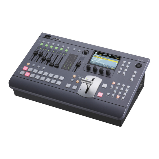
Multi format compact switcher
Hide thumbs
Also See for MCS-8M:
- Operating instructions manual (64 pages) ,
- Service manual (174 pages)
Table of Contents
Advertisement
Advertisement
Table of Contents

Related Manuals for Sony MCS-8M


Summary of Contents for Sony MCS-8M
- Page 1 Operating Instructions (Volume I Basic Operation) Before operating the unit, please read this manual thoroughly and retain it for future reference. MCS-8M Software Version 1.00 © 2011 Sony Corporation - 4 2 9 6 4 3 8 1 1 6 *...
- Page 2 To reduce the risk of fire or electric shock, refer servicing Record these numbers in the spaces provided below. to qualified service personnel. Refer to these numbers whenever you call upon your Sony dealer regarding this product. WARNING: THIS WARNING IS APPLICABLE FOR OTHER COUNTRIES.
- Page 3 (résidentiel), E2 (commercial et industrie légère), E3 (urbain extérieur) et E4 (environnement EMC contrôlé, ex. studio de télévision). Le fabricant de ce produit est Sony Corporation, 1-7-1 Konan, Minato-ku, Tokyo, Japon. Le représentant autorisé pour EMC et la sécurité des produits est Sony Deutschland GmbH, Hedelfinger Strasse 61, 70327 Stuttgart, Allemagne.
- Page 4 (Wohnbereich), E2 (kommerzieller und in beschränktem Maße industrieller Bereich), E3 (Stadtbereich im Freien) und E4 (kontrollierter EMV-Bereich, z.B. Fernsehstudio). Der Hersteller dieses Produkts ist Sony Corporation, 1-7-1 Konan, Minato-ku, Tokyo, Japan. Der autorisierte Repräsentant für EMV und Produktsicherheit ist Sony Deutschland GmbH, Hedelfinger Strasse 61, 70327 Stuttgart, Deutschland.
-
Page 5: Table Of Contents
Table of Contents Table of Contents (this manual) (Volume II Advanced Settings) (CD-ROM manual) Usage Precautions ............I-7 Chapter 1 Overview Chapter 1 Overview Introduction Introduction.................I-8 Names and Functions of Parts ........I-9 Chapter 2 Video Switching Overview Chapter 2 Preparations Setting the Transition Type Connecting Devices............I-15 General Transition Settings ([Misc] menu) Configuring System Settings ........I-17... -
Page 6: About This Manual
About This Manual Chapter 6 3D System Overview This manual describes the preparations necessary to use Making the Necessary Settings this unit and its basic operations. Basic video switching and composition operations and audio mixing can be performed by following the procedure Chapter 7 Controlling External in this manual. -
Page 7: Usage Precautions
URL mentioned in “Preparations” above. Note If you have lost or damaged the CD-ROM, you can purchase a new one to replace it. Contact your Sony service representative. Usage Precautions / Using the CD-ROM Manual... -
Page 8: Chapter 1 Overview
Overview Chapter Introduction The MCS-8M Multi Format Compact Switcher is a compact switcher that can be used in SD, HD, and 3D systems. This unit allows you to perform video switching with added effects and audio mixing via simple operations. -
Page 9: Names And Functions Of Parts
Names and Functions of Parts Front Panel 1 Audio control block (page I-9) 2 Menu control block (page I-10) Power switch (page I-16) USB connector (page I-13) 5 Numeric keypad block (page I-12) 4 Transition control block (page I-11) 3 Cross-point control block (page I-11) 1 Audio Control Block a ACCESS/PFL (access/pre-fade listen) buttons (page I-33, c Advanced Settings) -
Page 10: Menu Control Block
Viewing the menu screen 2 Menu Control Block R a t e M o n 0 0 0 1 Effect Back Effect Transition Wipe Adjust Wipe Edge P t n N u m Modify D i r e c t Enter Norm a Effect pattern area (page I-37) -
Page 11: Transition Control Block
a Bus delegation buttons Menu operations (c Advanced Settings) When you press a menu selection button or an ACCESS/ PFL button, setting items and values appear in the • BKGD (background) button (page I-35) parameters area at the bottom of the screen. You can use •... - Page 12 g Fader lever (page I-26) Entering numeric values h KEY TRANS (key transition) button The numeric buttons are used to enter numeric values for operations such as specifying effect pattern numbers and (c Advanced Settings) saving or recalling snapshots. 1 Press the EFF button or SNAPSHOT button to light it. Using the next transition selection buttons (When specifying an effect pattern number, be sure to Turn on (i.e., light) the buttons by pressing them to specify...
-
Page 13: Rear Panel
Rear Panel 2 Audio input block (page I-13) 1 Audio output block (page I-13) 5 Video input block (page I-14) 4 Reference signal input/output block (page I-14) 3 Video output block (page I-14) a Anti-theft cable slot d AUX OUT (auxiliary output) 1 and 2 connectors Connect a commercially available anti-theft cable (TRS phone) (3 mm ×... - Page 14 3 Video Output Block 5 Video Input Block a VIDEO IN (video input) 1 to 3 connectors (BNC type) (page I-19) a VIDEO OUT AUX (video output auxiliary) b HDMI IN (HDMI input) 1 to 3 connectors connector (BNC type) (c Advanced Settings) (page I-19) This output is used for confirming video.
-
Page 15: Chapter 2 Preparations
Preparations Chapter Connecting Devices Connect each device to the rear panel of the unit. Connection example: HD system CD/DVD player LINE IN Microphone PGM OUT MIC/LINE IN REF IN Ω terminator HEADPHONE DVI-I IN Headphones DVI-D OUT Computer DVI⇔HDMI (presenter) DVI-D OUT conversion cable SDI IN... -
Page 16: Turning The Unit Off
Raise or lower the fader lever all the way up or down. Notes • When you are using a reference signal generator, and do Fader lever not want to perform loop-through output of the reference signal input to one of the REF IN connectors of the unit, attach a 75 Ω... -
Page 17: Configuring System Settings
Turn the V1 knob to select [System Format], and Configuring System select the signal format and aspect ratio with the respective knobs. Settings R a t e M o n 0 0 0 1 System Configure the system mode, system date and time, and Back other system settings in the menu control block. -
Page 18: Configuring The Date And Time
Turn the V1 knob to select [Time], and set the clock Notes with the respective knobs. • When the signal format is set to an HD mode, the 4:3 aspect ratio cannot be selected. R a t e M o n •... -
Page 19: Configuring Video Signal Settings
Press the SETUP button to display the [Setup] menu. Configuring Video Signal Turn the V1 knob to select [Video (XPT)], and press Settings the knob. R a t e M o n 0 0 0 1 Configure settings for handling video signals on the unit. Setup 5/11 Audio... - Page 20 Notes on setting values XGA: Analog, 1024 768/60 × The following assignments are set under factory default SXGA: Analog, 1280 1024/60 × settings. WXGA: Analog, 1280 768/60 × HDTV50: Digital, 1080p/50 PGM, PST/KEY Default setting HDTV60: Digital, 1080p/60 cross-point button SDI1 Note SDI2...
-
Page 21: Configuring Audio Signal Settings
Turn the V1 knob to select the channel fader number Configuring Audio Signal ([Audio Input Assign 1] to [Audio Input Assign 6]) to which you want to assign the audio signal, and select Settings the audio signals for L and R with the respective knobs. - Page 22 Repeat step 3 to configure the levels for the other MIC/ Configuring the Mic/Line Levels for LINE IN connectors. Audio Inputs Setting example: If a peak indicator lights at the default setting of Adjustment of mic/line levels is necessary when the peak [–20 dB], select the [+4 dB] setting.
-
Page 23: Configuring Multi Viewer Settings
When using the Multi Viewer, specify the video output for Configuring Multi Viewer each sub-screen. Settings Press the SETUP button to display the [Setup] menu. Turn the V1 knob to select [Multi Viewer], and press the knob. The Multi Viewer allows you to display multiple video inputs, program video outputs, and preview video outputs simultaneously on a monitor connected to the unit. - Page 24 Notes on setting values Black: Black video SDI1 to 4: Video input from the SDI IN 1 to 4 connectors DVI: Video input from the DVI-I IN connector H/V1 to 3: Video input from the HDMI IN 1 to 3 connectors or VIDEO IN 1 to 3 connectors ColBg: Color background video FM-V: Frame memory video...
-
Page 25: Chapter 3 Basic Operations
Basic Operations Chapter PGM cross-point buttons Switching Video Switch between video signals that are input to the unit, compose images, and output programs from the PGM output connector. This section describes simple operations for switching video and applying effects while switching. The button that is lit red indicates Frequently used effects can be saved as “snapshots”... -
Page 26: Applying Effects While Switching (Mix/Effect
Press the CUT button in the transition control block. Example: Frame In/Out (page I-27) With this effect, the next video is superimposed as a frame within the current program video output and gradually expands to replace the current video. Superimposed frame Multiple patterns may be available for certain effects. -
Page 27: Configuring The Transition Rate
Fader lever (manual execution) R a t e M o n The video switches over as you move the lever. 0 0 0 1 Move the lever in the direction of the lit transition Misc indicator. The transition starts, and proceeds according to Transition Rate (1/2) the rate at which you move the lever. -
Page 28: Composing Images With Keys
Select an effect in the numeric keypad block. Composing Images with Keys Keying is a function in which part of the background image is replaced by another image or superimposed text. The following keys can be used with this unit to compose video. -
Page 29: Composing Images With Luminance Keys
Composing Images with Luminance Keys Press the KEY bus delegation button. Knob Parameter Meaning Setting values Press the PGM cross-point button of the video for Type Key type Lum (luminance key), selection Lin (linear key), program output. Chr (chroma key) Press the PST/KEY cross-point button of the key If necessary, you can also configure the clip value material (i.e., the image to be superimposed on the... -
Page 30: Composing Images With Chroma Keys
Selecting the key fill and key source Knob Parameter Meaning Setting values separately Source Key source Self, Auto, Split selection mode Perform the following between step 7 and 8 of the previous procedure. 2 Press the PST/KEY cross-point button to be used for the key source while holding down the KEY bus 1 Turn the V1 knob to select [Key Fill/Src Select], and delegation button. - Page 31 Press the KEY button in the menu control block to Turn the V1 knob to select [Sample Mark], and press display the [Key] menu. the V4 knob. Turn the V1 knob to select [Key Type Select], and turn R a t e M o n the V4 knob to select [Chr].
-
Page 32: Mixing Audio
Turn the V1 knob to select [Auto Adjust Execute], and Mixing Audio press the V4 knob. R a t e M o n 0 0 0 1 Mix audio that is input to the unit, and output the final Auto Chromakey audio (i.e., program output) from the PGM OUT connector Back of the audio output block. - Page 33 Switching audio for monitoring Adjusting audio levels for monitoring Press the MONITOR SEL button to select [PGM]. Use the MONITOR LEVEL adjustment knob and the DIM The button lights orange for a moment and the audio for button to adjust the level of the audio that is output to monitoring switches in the following sequence with each devices connected to the MON OUT L and R connectors press.
-
Page 34: Snapshots
Press the STORE button. Snapshots The snapshot is registered. The snapshot function allows you to save effect and key If you enter a number that is already in use, the settings for specific scenes. By saving frequently used previous snapshot will be overwritten. settings as snapshots, you can quickly recall settings when necessary. -
Page 35: Saving And Selecting Settings
Saving and Selecting To recall a snapshot without changing the cross-point, Settings press the ENTER button while holding down the PGM cross-point button and/or PST/KEY cross-point button. You can save the current settings for effects, keys, and Cross-point row Unchanged setup. - Page 36 Selecting the Settings Recalled at Startup Press the SETUP button to display the [Setup] menu. Turn the V1 knob to select [System], and press the knob. R a t e M o n 0 0 0 1 Setup 2/11 Startup Define System Audio Video (Input)
-
Page 37: Appendix
Appendix Squeeze Effect Pattern List 1021 1022 1023 1024 1025 1026 Wipe 1027 1028 1029 1030 1031 Door 1041 1042 1043 1044 Frame In/Out 1201 1202 1203 1204 1205 1206 1207 1208 1221 1222 1223 1224 Flip Tumble NAM (non-additive mix) 1101 1102 Slide... -
Page 38: Troubleshooting
Troubleshooting Please verify the problem again. If the problem persists, contact your local Sony representative. Problem Possible cause Solution The video output is not displayed and The FTB button is lit (on). Turn the FTB button off. the display is black. -
Page 39: Maintenance
Maintenance Remove dust from the ventilation holes once a month or whenever the holes are dirty. 420 mm (16 in.) Specifications General Supported formats 1080i/ 50 Hz, 59.94 Hz 720p/ 50 Hz, 59.94 Hz 480i/ 59.94 Hz 576i/ 50 Hz Power 100 to 240 V AC ±10%, 50/60 Hz Power consumption... -
Page 40: Audio Input
Supported input formats Supported output formats • HD/SD system • HD/SD system SD/HD Input SDI IN HDMI IN DVI-I IN VIDEO IN REF IN SD/HD Output SDI OUT DVI-D OUT VIDEO OUT AUX REF OUT 1 to 4 1 to 3 1 to 3 Digital Format... - Page 41 • Always make a test recording, and verify that it was Standard stereo PHONE (1) recorded successfully. Max. output: 25 mW × 2 (16 Ω load) SONY WILL NOT BE LIABLE FOR DAMAGES OF ANY KIND INCLUDING, BUT NOT LIMITED TO, COMPENSATION OR REIMBURSEMENT ON Other interfaces...
-
Page 42: Remote Connector
Pin Configurations Example Connection of GPI Input Switch or relay connection TALLY/GPI connector 15-pin D-sub, male External device MCS-8M Pin No. Signal name Description GPO1 GPI output 1 / tally 1 10 kΩ GPO2 GPI output 2 / tally 2... -
Page 43: Index
AUX OUT Assign II-33 DME Wipe Modify Menu II-18 Index Crop H II-18 Crop V II-18 Positioner II-18 BKGD Button I-11, I-12, I-35 Positioner Adjust II-18 Numerics Border Adjust II-25 Size II-18 Border Matte Adjust II-25 3D Mode II-41, II-48 Door I-37 Bus Delegation II-9 3D System II-40... - Page 44 Fine Key Adjust V II-25 Key Edge Type II-25 Location II-26 Flip Tumble I-37 Key Fill Mat Adjust II-23 Lum I-29 FM Button I-10, II-34 Key Fill/Src Select II-23 Lum Key Adjust II-23 Formatting USB Flash Drive II-39 Key Invert II-24 Lum Key Mode II-23 Frame In/Out I-26, I-37 Key Mask II-25...
- Page 45 Audio II-49 Turning the Unit On/Off I-16 GPI/Tally II-44 On Air Source II-46 Information II-54 Oscillator II-50 Install II-54 Output Level II-50 USB Memory Format II-39 Multi Viewer I-23 Startup Define I-35 System II-47 Video (Input) II-51 Pan II-32 V1 I-11 Video (Misc) II-54 Peak Indicator I-9, I-22 V2 I-11...
- Page 46 XPT Shift Mode II-52 X-Y Pointer I-10, II-11, II-13 I-46 Index...
- Page 47 The material contained in this manual consists of Trademarks information that is the property of Sony Corporation and is HDMI, the HDMI logo and High-Definition Multimedia intended solely for use by the purchasers of the equipment Interface are trademarks or registered trademarks of described in this manual.
- Page 48 Sony Corporation Printed in China...
Need help?
Do you have a question about the MCS-8M and is the answer not in the manual?
Questions and answers