Sony MCS-8M Service Manual
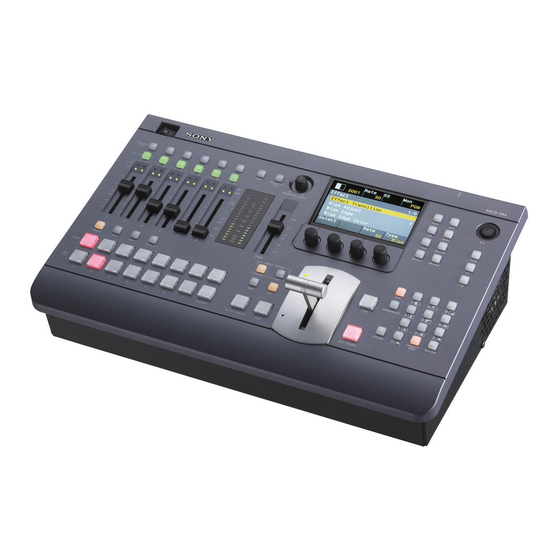
Multi format compact switcher
Hide thumbs
Also See for MCS-8M:
- Operating instructions manual (48 pages) ,
- Operating instructions manual (64 pages)
Table of Contents
Advertisement
Quick Links
Advertisement
Table of Contents

Related Manuals for Sony MCS-8M


Summary of Contents for Sony MCS-8M
- Page 1 MULTI FORMAT COMPACT SWITCHER MCS-8M SERVICE MANUAL 1st Edition...
- Page 2 Ce manual est destiné uniquement aux personnes compétentes en charge de l’entretien. Afin de réduire les risques de décharge électrique, d’incendie ou de blessure n’effectuer que les réparations indiquées dans le mode d’emploi à moins d’être qualifié pour en effectuer d’autres. Pour toute réparation faire appel à une personne compétente uniquement. MCS-8M...
- Page 3 Batterien nur durch den vom Hersteller empfohlenen Kasser batteriet i henhold til gjeldende avfallsregler. oder einen gleichwertigen Typ ersetzen. Wenn Sie die Batterie entsorgen, müssen Sie die Gesetze der jeweiligen Region und des jeweiligen Landes befolgen. MCS-8M...
-
Page 5: Table Of Contents
Replacing Fuse......................1-40 MCS-8M... - Page 6 Board Parts Location........................5-5 MCS-8M...
-
Page 7: Manual Structure
MIX-54 and KY-671 boards. Related manuals In addition to this Service Manual, the following manual is provided for MCS-8M. Operating Instructions (Supplied with this unit.) This manual is required for the operation and use of this unit, as well as for installation. -
Page 9: Service Overview
Current consumption 0.7 to 0.3 A Recommended Power Cord This unit does not come with a power cord. To get a power cord, please contact your local Sony Sales Office/Service Center. WARNING • Use the approved Power Cord (3-core mains lead)/Appliance Connector/Plug with earthing-contacts that conforms to the safety regulations of each country if applicable. -
Page 10: External Dimensions
• Use the Power Cord (3-core mains lead)/Appliance Connector/Plug conforming to the proper ratings (Voltage, Ampere). If you have questions on the use of the following Power Card/Plug, please contact your local Sony Sales Office/Service Center. WARNING • Never use an injured power cord. -
Page 11: Matching Connectors And Cables
1-1-4. Matching Connectors and Cables Use the following connectors/cables or their equivalents when connecting cables to connectors of this unit. AUDIO IN Panel indica- Connector Matching connector/ Sony part No. Usage for tion cable MIC/LINE IN 1, 2 XLR/TRS combo 3-pin,... -
Page 12: Input/Output Signals Of Connectors
Panel indica- Connector Matching connector/ Sony part No. Usage for tion cable SDI OUT BNC, 75 Ω BNC, 5CFB coaxial cable — SDI video output PGM, AUX1, (75 Ω) AUX2, MULTI VIEWER Panel indica- Connector Matching connector/ Sony part No. - Page 13 Transmitted data • Maximum output level: +24 dBu Data terminal ready • Output impedance: 150 Ω — Ground • Chip: HOT Data set ready • Ring: COLD Request to send • Sleeve: GND Clear to send — — No connection MCS-8M...
- Page 14 Digital clock signal (+) Clock – Digital clock signal (–) Analog Red Analog video signal, red Analog Green Analog video signal, green Analog Blue Analog video signal, blue Analog Horizontal Sync Analog horizontal syn- chronizing signal Analog Ground Analog signal ground MCS-8M...
- Page 15 Data 0 + Digital video signal, blue Data 0/5 shield Shield Data 5 – Not used Data 5+ Not used Clock shield Clock shield Clock + Digital clock signal (+) Clock – Digital clock signal (–) Ground Analog signal ground MCS-8M...
- Page 16 INPUT 20. TALLY/GPI: D-sub (15-pin, Male) Switch or relay connection External device MCS-8M (External View) INPUT x 4: TTL OUTPUT x 8: Open collector ( Maximum Current 5 mA , Maximum Voltage 5 V) Signal name Function GPO1 GPI Output 1/Tally 1...
-
Page 17: Functions Of Onboard Switches, Leds, And Connectors
Indicates the configuration status of FPGAs other than the CPU control FPGA (IC5004). Lights when the configuration of FPGAs (IC5001, IC5002, IC5003, IC5005) other than the CPU control FPGA (IC5004) has been successfully completed. D1500 to D1507 (E, F-6): Image processing device status LEDs Indicate the image processing device (IC6) status. MCS-8M... - Page 18 OFF: Normal startup ON: Forcible startup with the factory mode. Connectors CN300 (K-8): EPR2 CPLD data write connector Used for writing configuration data to the CPLD (IC300). 1-10 MCS-8M...
- Page 19 Used for writing FPGA configuration data to IC2907 (Config ROM for IC5001), IC2908 (Config ROM for IC5002), IC2909 (Config ROM for IC5003), IC5004, and IC5005. CN1002 (K-8): DEBUG CPU serial communication (RS-232C) connector Used for checking CPU operation. 1-11 MCS-8M...
-
Page 20: Location Of Main Parts (Boards)
1-2. Location of Main Parts (Boards) KY-671 board CN-3403 board SW-1521 board CN-3404 board MIX-54 board VR-345 board LCD module Switching regulator Pointer DC fan (80 square ) Fader assembly 1-12 MCS-8M... -
Page 21: Replacement Of Main Parts
Top panel assembly Rear side Disconnect the flexible flat cable (45 cores) from the connector CN353 on the KY-671 board. Release the harness from the harness clamp and disconnect the harness from the connector CN1401 on the KY-671 board. 1-13 MCS-8M... -
Page 22: Switching Regulator
CN1401 (KY-671 board) Harness Clamp CN353 (KY-671 board) Flexible flat cable (45 core) Install the removed parts by reversing the steps of removal. 1-3-2. Switching Regulator Preparation Remove the top panel assembly. (Refer to “1-3-1. Top Panel Assembly”.) 1-14 MCS-8M... -
Page 23: Dc Fan (80 Square)
Switching regulator Clamp Harness (PSW) Connectors Harness Install the removed parts by reversing the steps of removal. 1-3-3. DC Fan (80 Square) Preparation Remove the top panel assembly. (Refer to “1-3-1. Top Panel Assembly”.) 1-15 MCS-8M... -
Page 24: Lcd Module
Pay attention to the orientation of the DC fan (80 square) when installing it. 1-3-4. LCD Module Preparation Remove the top panel assembly. (Refer to “1-3-1. Top Panel Assembly”.) Remove the KY-671 board. (Refer to “1-3-9. KY-671 Board”.) 1-16 MCS-8M... -
Page 25: Fader Assembly/Vr-345 Board
• Do not install the LCD plate on any boss. LCD plate Boss Boss • When installing the LCD bracket, do not catch the flexible board of the LCD module. 1-3-5. Fader Assembly/VR-345 Board Preparation Remove the top panel assembly. (Refer to “1-3-1. Top Panel Assembly”.) 1-17 MCS-8M... - Page 26 Remove the two screws and remove the fader assembly. PSW3 x 8 Fader assembly CN402 (VR-345 board) Harness Remove the two screws and remove the VR-345 board. VR-345 board PSW3 x 8 Install the removed parts by reversing the steps of removal. 1-18 MCS-8M...
-
Page 27: Cn-3403 Board
Remove the two screws (BVTP3 x 8), two screws (P2.6 x 4), and two screws (BVTT2.5) to remove the CN-3403 board. CN-3403 board PSW3 x 8 BVTP3 x 8 P2.6 x 4 BVTT2.5 (S) P2.6 x 4 Install the removed parts by reversing the steps of removal. 1-19 MCS-8M... -
Page 28: Cn-3404 Board
Remove the board assembly-2. (Refer to “1-3-6. CN-3403 Board”.) Remove the switching regulator. (Refer to “1-3-2. Switching Regulator”.) Procedure Release the harness from the harness clamp. Disconnect the two harnesses from the two connectors (CN3300 and CN901) on the MIX-54 board. 1-20 MCS-8M... - Page 29 Remove the seven screws (PSW3 x 8) and three screws (B3 x 6) to remove the harness clamp and the board assembly-1. PSW3 x 8 Clamp Board assembly-1 Clamp B3 x 6 Disconnect the flexible flat cable (50 core) from the connector (CN4900) on the MIX-54 board. 1-21 MCS-8M...
- Page 30 Remove the seven audio fader knobs and the volume knob. Audio fader knobs Volume knob Disconnect the flexible board from the connector CN405 on the KY-671 board. Disconnect the flexible board from the connector CN407 on the KY-671 board. 1-22 MCS-8M...
-
Page 31: Sw-1521 Board
Install the removed parts by reversing the steps of removal. Note Match the bosses and the two holes when installing the KY-671 board. 1-3-10. SW-1521 Board Preparation Remove the top panel assembly. (Refer to “1-3-1. Top Panel Assembly”.) Remove the KY-671 board. (Refer to “1-3-9. KY-671 Board”.) 1-23 MCS-8M... -
Page 32: Lithium Battery
Remove the two screws to remove the SW-1521 board. PSW3 x 8 Harness (SW) SW-1521 board CN404 Install the removed parts by reversing the steps of removal. 1-3-11. Lithium Battery Preparation Remove the top panel assembly. (Refer to “1-3-1. Top Panel Assembly”.) 1-24 MCS-8M... -
Page 33: Pointer
WP clamp Pointer Install the removed parts by reversing the steps of removal. 1-3-13. Dust Protection Sheet Preparation Remove the top panel assembly. (Refer to “1-3-1. Top Panel Assembly”.) Remove the insulation sheet (PS). (Refer to “1-3-2. Switching Regulator”.) 1-25 MCS-8M... -
Page 34: Notes For Replacing Boards
Press the SETUP button beside the menu display of the unit. Select "System" with the [V1] knob and press the [V1] knob. Turn the [V1] knob to move the cursor to "Back" at the bottom of the item list. 1-26 MCS-8M... - Page 35 Connect the frequency counter to MULTI VIEWER of SDI-OUT. Adjust the frequency counter to 13.5 MHz ±20 Hz with the [V3] knob. 10. Press the [V3] knob to memorize the adjustment result. 11. Turn off the power of the unit. 12. Disconnect the frequency counter. 1-27 MCS-8M...
-
Page 36: Periodic Check Parts
Remove the fan according to the fan removal procedure. (Refer to “1-3-3. DC Fan (80 Square)”.) Clean the fan frame and blades with a cleaning cloth dampened with cleaning fluid. - Cleaning cloth (Sony part No.: 3-184-527-01) - Cleaning fluid (Sony part No.: 9-919-573-01) DC fan (80 square) Harness lock... - Page 37 Note • If much dust is present, remove the dust protection sheet from the adhesive tape and wash it with water. • After the dust protection sheet is washed, dry it completely. Dust protection sheet Adhesive tape Case 1-29 MCS-8M...
-
Page 38: Message List
In case the error still remains despite correct cable connection, replace the cable. 4005 Unable to start. The video/audio signal processor device is not working correctly. Reinstall Please restart. the firmware. In case the error still remains despite correct firmware installa- tion, replace the MIX-54 board. Continued 1-30 MCS-8M... - Page 39 Message Solution 4201 Loading configuration file error. The selected configuration file may not be an MCS-8M supported file, or it may be damaged. 4202 Saving configuration file error. The configuration file could not be saved. The USB flash drive may be mal- Please retry.
- Page 40 F: Firmware • R: Register • Font: Font • "O" : OK "E" : Error " - " : Not installed 1103 Import Finished. This appears when import of a configuration file is complete. Restart the unit. Please restart. 1-32 MCS-8M...
-
Page 41: Version Update
Select "Install ▶ " (last of the item list) with the [V1] knob and press the [V1] knob. Press the [V4] knob to start installation. A message "Waiting..." is displayed in the sub-title area during the installation. R a t e M o n 0 0 0 1 Install Waiting... 1-33 MCS-8M... - Page 42 Wait for about 30 seconds. Panel operations are disabled during this time period. Note Do not turn off the power until the backup is completed. After about 30 seconds have passed, confirm that panel operations are enabled. Enabled panel operation shows that the backup has been completed. 1-34 MCS-8M...
-
Page 43: Recovery In Case Installation Of Installation Module Fails
Re-set the unit mode to the normal operation mode Set all pins of the DIP-SW S300 and DIP-SW S301 on the MIX-54 board to OFF. Checking after installation Refer to "Checking after installation" in “1-6-1. Version Update from the USB Memory” 1-35 MCS-8M... -
Page 44: Circuit Description
1-7-1. Board Description MIX-54 Board This main board of MCS-8M contains main components such as a video signal input/output circuit, a digital video processing circuit, a digital audio processing circuit, a control CPU circuit, and a circuit for controlling switches, LEDs, and LCD on the panel . -
Page 45: Audio Signal Processing Circuit
Processing commands to the DSP (IC5105) are executed through the S-RAM (IC5000) connected to the CPU bus. 1-7-4. Control Circuit The MCS-8M controls entire control system with a single-chip CPU (IC10). This circuit has a 2-Mbyte boot flash memory (IC1201) for booting, a 64-Mbyte flash memory (IC1200) for storing application programs, and a 128-Mbyte work SDRAM (IC200 to IC203). -
Page 46: Synchronization Circuit
1-7-5. Synchronization Circuit The MCS-8M controls entire control system with a single-chip CPU (IC10). This circuit has a 2-Mbyte boot flash memory (IC1201) for booting, a 64-Mbyte flash memory (IC1200) for storing application programs, and a 128-Mbyte work SDRAM (IC200 to IC203). -
Page 47: Lead-Free Solder
• The ordinary soldering iron can be used but the iron tip has to be applied to the solder joint for a slightly longer time. The printed pattern (copper foil) may peel away if the heated tip is applied for too long, so be careful. 1-39 MCS-8M... -
Page 48: Circuit Protection Parts
The fuse is essential parts for safe operation. Replace the components with Sony parts whose part numbers appear in the manual published by Sony. If the components are replaced with any parts other than the specified ones, this may cause a fire or electric shock. -
Page 49: Spare Parts
Therefore, specified parts should be used in the case 指定の部品を使ってください。 of replacement. 2. Standardization of Parts 2. 部品の共通化 Some repair parts supplied by Sony differ from those ソニーから供給する補修用部品は,セットに使われ used for the unit. These are because of parts common- ているものと異なることがあります。 ality and improvement. -
Page 50: Exploded Views
2-2. Exploded Views Overview Refer to “Panel Assembly-1” Refer to “Case Assembly-1” B3 x 6 B3 x 6 Part No. SP Description 4-296-293-01 s KNOB, AUDIO FADER 4-296-302-01 s KNOB, VOLUME 7-682-547-09 s SCREW +B 3X6 MCS-8M... - Page 51 1-831-087-11 s CABLE, FLEXIBLE FLAT (50 CORE) 3-776-750-02 s SCREW +BVTT 2.5(S) 4-296-313-01 s SHEET, DUST PROTECTION 4-296-316-01 s TAPE, ADHESIVE 7-621-284-00 s SCREW +P 2.6X4 7-682-547-09 s SCREW +B 3X6 7-685-646-79 s SCREW +BVTP 3X8 TYPE2 IT-3 7-682-948-01 s SCREW +PSW 3X8 MCS-8M...
- Page 52 1-787-908-11 s FAN, DC (80 SQUARE) 1-831-157-11 s CABLE, FLEXIBLE FLAT (50 CORE) 1-839-555-11 s CABLE, FLEXIBLE FLAT (45 CORE) 7-621-284-00 s SCREW +P 2.6X4 7-682-547-09 s SCREW +B 3X6 7-682-568-09 s SCREW +B 4X30 7-682-948-01 s SCREW +PSW 3X8 MCS-8M...
- Page 53 X-2582-828-1 s CASE ASSY 1-251-384-12 s INLET (WITH NOISE FILTER) 1-771-124-21 s SWITCH, POWER 2-068-008-00 s WASHER 2-990-241-02 s HOLDER (A), PLUG 3-714-101-01 s LEG (FRONT) 7-682-948-01 s SCREW +PSW 3X8 7-682-950-01 s SCREW +PSW 3X12 7-682-961-01 s SCREW +PSW 4X8 MCS-8M...
- Page 54 1-968-041-11 s SUB HARNESS (VR) 3-853-744-01 s PLATE, DIFFUSION (15) 4-145-371-01 s CAP (15) 4-296-299-01 s PARTS, AUDIO FADER LIGHT GUIDE 4-296-300-01 s PARTS, SMALL SWITCH LIGHT GUIDE 4-296-301-01 s PLATE, AUDIO LIGHT SHIELD 7-682-948-01 s SCREW +PSW 3X8 MCS-8M...
- Page 55 A-1820-579-A s MOUNTED CIRCUIT BOARD, VR-345 A-1820-580-A s MOUNTED CIRCUIT BOARD, SW-1521 A-1849-215-A s PANEL (S) ASSY, UPPER 1-788-165-11 s POINTER 1-811-489-11 s LCD MODULE 1-968-042-11 s SUB HARNESS (SW) 3-701-508-00 s SET SCREW, DOUBLE POINT 3X6 7-682-948-01 s SCREW +PSW 3X8 MCS-8M...
-
Page 56: Electrical Parts List
1-112-298-91 s CAP, CERAMIC 1MF B (1608) C1310 1-114-582-91 s CAP, CERAMIC 0.1MF B 1005 C408 1-112-298-91 s CAP, CERAMIC 1MF B (1608) C1311 1-114-582-91 s CAP, CERAMIC 0.1MF B 1005 C409 1-112-298-91 s CAP, CERAMIC 1MF B (1608) MCS-8M... - Page 57 6-502-598-01 s DI SML-D12U8WT86 D1113 8-719-069-28 s DI 1SS400FJTE61 D539 6-502-197-01 s DI SML-D12M8WT86SM D1114 8-719-069-28 s DI 1SS400FJTE61 D540 6-502-598-01 s DI SML-D12U8WT86 D1115 8-719-069-28 s DI 1SS400FJTE61 D541 6-502-197-01 s DI SML-D12M8WT86SM D1116 8-719-069-28 s DI 1SS400FJTE61 MCS-8M...
- Page 58 6-502-352-01 s DI SML-522MU8WT86PQ D8070 6-502-352-01 s DI SML-522MU8WT86PQ D8006 6-502-352-01 s DI SML-522MU8WT86PQ D8071 6-502-352-01 s DI SML-522MU8WT86PQ D8007 6-502-352-01 s DI SML-522MU8WT86PQ D8072 6-502-352-01 s DI SML-522MU8WT86PQ D8008 6-502-352-01 s DI SML-522MU8WT86PQ D8073 6-502-352-01 s DI SML-522MU8WT86PQ 2-10 MCS-8M...
- Page 59 6-707-414-01 s IC DS90LV011ATMF D9038 6-502-352-01 s DI SML-522MU8WT86PQ IC108 6-707-414-01 s IC DS90LV011ATMF D9040 6-502-352-01 s DI SML-522MU8WT86PQ IC201 6-712-387-01 s IC TC74VHC165FT(EKJ) D9041 6-502-352-01 s DI SML-522MU8WT86PQ IC202 6-701-870-01 s IC THC63LVDF84B-T D9042 6-502-352-01 s DI SML-522MU8WT86PQ 2-11 MCS-8M...
- Page 60 1-456-826-11 s COIL, COMMON MODE CHOKE Q707 8-729-929-09 s TRANSISTOR DTC123JE-TL LF203 1-456-826-11 s COIL, COMMON MODE CHOKE Q708 8-729-929-09 s TRANSISTOR DTC123JE-TL Q709 8-729-929-09 s TRANSISTOR DTC123JE-TL 1-533-282-21 s LINK, IC (2A/72V) Q710 8-729-929-09 s TRANSISTOR DTC123JE-TL 2-12 MCS-8M...
- Page 61 8-729-929-09 s TRANSISTOR DTC123JE-TL Q933 8-729-929-09 s TRANSISTOR DTC123JE-TL Q809 8-729-929-09 s TRANSISTOR DTC123JE-TL Q934 8-729-929-09 s TRANSISTOR DTC123JE-TL Q810 8-729-929-09 s TRANSISTOR DTC123JE-TL Q935 8-729-929-09 s TRANSISTOR DTC123JE-TL Q811 8-729-929-09 s TRANSISTOR DTC123JE-TL Q936 8-729-929-09 s TRANSISTOR DTC123JE-TL 2-13 MCS-8M...
- Page 62 1-218-990-81 s CONDUCTOR, CHIP (1005) R280 1-220-878-81 s RES, CHIP 22 (1005) R216 1-220-878-81 s RES, CHIP 22 (1005) R281 1-220-878-81 s RES, CHIP 22 (1005) R217 1-220-878-81 s RES, CHIP 22 (1005) R282 1-220-878-81 s RES, CHIP 22 (1005) 2-14 MCS-8M...
- Page 63 1-218-990-81 s CONDUCTOR, CHIP (1005) R543 1-220-878-81 s RES, CHIP 22 (1005) R403 1-208-887-81 s RES, CHIP 1.0K (1005) R544 1-220-878-81 s RES, CHIP 22 (1005) R404 1-208-919-81 s RES, CHIP 22K (1005) R545 1-220-878-81 s RES, CHIP 22 (1005) 2-15 MCS-8M...
- Page 64 1-208-871-81 s RES, CHIP 220 (1005) R680 1-220-878-81 s RES, CHIP 22 (1005) R612 1-208-879-81 s RES, CHIP 470 (1005) R681 1-220-878-81 s RES, CHIP 22 (1005) R613 1-208-871-81 s RES, CHIP 220 (1005) R682 1-220-878-81 s RES, CHIP 22 (1005) 2-16 MCS-8M...
- Page 65 1-220-878-81 s RES, CHIP 22 (1005) R860 1-208-871-81 s RES, CHIP 220 (1005) R758 1-220-878-81 s RES, CHIP 22 (1005) R861 1-208-871-81 s RES, CHIP 220 (1005) R759 1-220-878-81 s RES, CHIP 22 (1005) R862 1-208-871-81 s RES, CHIP 220 (1005) 2-17 MCS-8M...
- Page 66 1-220-878-81 s RES, CHIP 22 (1005) R1308 1-208-959-81 s RES, CHIP 1M (1005) R940 1-220-878-81 s RES, CHIP 22 (1005) R1309 1-208-879-81 s RES, CHIP 470 (1005) R941 1-220-878-81 s RES, CHIP 22 (1005) R1311 1-208-855-81 s RES, CHIP 47 (1005) 2-18 MCS-8M...
- Page 67 1-208-879-81 s RES, CHIP 470 (1005) R8102 1-208-871-81 s RES, CHIP 220 (1005) R8038 1-208-871-81 s RES, CHIP 220 (1005) R8103 1-208-879-81 s RES, CHIP 470 (1005) R8039 1-208-879-81 s RES, CHIP 470 (1005) R8104 1-208-871-81 s RES, CHIP 220 (1005) 2-19 MCS-8M...
- Page 68 1-208-879-81 s RES, CHIP 470 (1005) R9032 1-208-871-81 s RES, CHIP 220 (1005) R8168 1-208-871-81 s RES, CHIP 220 (1005) R9033 1-208-879-81 s RES, CHIP 470 (1005) R8169 1-208-879-81 s RES, CHIP 470 (1005) R9034 1-208-871-81 s RES, CHIP 220 (1005) 2-20 MCS-8M...
- Page 69 1-771-721-21 s SWITCH, TACTILE R9097 1-208-879-81 s RES, CHIP 470 (1005) S1151 1-771-721-21 s SWITCH, TACTILE R9098 1-208-871-81 s RES, CHIP 220 (1005) S1152 1-771-721-21 s SWITCH, TACTILE S1153 1-771-721-21 s SWITCH, TACTILE R9099 1-208-879-81 s RES, CHIP 470 (1005) 2-21 MCS-8M...
- Page 70 1-114-582-91 s CAP, CERAMIC 0.1MF B 1005 C110 1-114-582-91 s CAP, CERAMIC 0.1MF B 1005 C601 1-114-582-91 s CAP, CERAMIC 0.1MF B 1005 C111 1-114-582-91 s CAP, CERAMIC 0.1MF B 1005 C602 1-114-582-91 s CAP, CERAMIC 0.1MF B 1005 2-22 MCS-8M...
- Page 71 1-114-582-91 s CAP, CERAMIC 0.1MF B 1005 C756 1-114-582-91 s CAP, CERAMIC 0.1MF B 1005 C1109 1-114-582-91 s CAP, CERAMIC 0.1MF B 1005 C757 1-114-582-91 s CAP, CERAMIC 0.1MF B 1005 C1110 1-114-582-91 s CAP, CERAMIC 0.1MF B 1005 2-23 MCS-8M...
- Page 72 1-114-582-91 s CAP, CERAMIC 0.1MF B 1005 C1695 1-100-581-81 s CAP,CHIP CERAMIC0.0047MF B1005 C1615 1-114-582-91 s CAP, CERAMIC 0.1MF B 1005 C1696 1-112-692-81 s CAP,CHIP CERAMIC1000PF CH 1005 C1616 1-114-582-91 s CAP, CERAMIC 0.1MF B 1005 C1697 1-100-581-81 s CAP,CHIP CERAMIC0.0047MF B1005 2-24 MCS-8M...
- Page 73 1-114-582-91 s CAP, CERAMIC 0.1MF B 1005 C1809 1-114-582-91 s CAP, CERAMIC 0.1MF B 1005 C1874 1-114-582-91 s CAP, CERAMIC 0.1MF B 1005 C1810 1-114-582-91 s CAP, CERAMIC 0.1MF B 1005 C1875 1-114-582-91 s CAP, CERAMIC 0.1MF B 1005 2-25 MCS-8M...
- Page 74 1-114-528-21 s CAP, ELECT 150MF C2435 1-114-415-21 s CAP, ELECT 100MF (5X5.9) C2153 1-114-528-21 s CAP, ELECT 150MF C2436 1-100-567-81 s CAP,CHIP CERAMIC 0.01MF B 1005 C2154 1-114-528-21 s CAP, ELECT 150MF C2438 1-100-567-81 s CAP,CHIP CERAMIC 0.01MF B 1005 2-26 MCS-8M...
- Page 75 1-100-881-91 s CAP, CERAMIC 47MF C (3216) C2527 1-100-567-81 s CAP,CHIP CERAMIC 0.01MF B 1005 C2617 1-100-881-91 s CAP, CERAMIC 47MF C (3216) C2528 1-100-567-81 s CAP,CHIP CERAMIC 0.01MF B 1005 C2618 1-100-881-91 s CAP, CERAMIC 47MF C (3216) 2-27 MCS-8M...
- Page 76 1-100-567-81 s CAP,CHIP CERAMIC 0.01MF B 1005 C2687 1-114-582-91 s CAP, CERAMIC 0.1MF B 1005 C2769 1-114-582-91 s CAP, CERAMIC 0.1MF B 1005 C2688 1-100-567-81 s CAP,CHIP CERAMIC 0.01MF B 1005 C2770 1-100-567-81 s CAP,CHIP CERAMIC 0.01MF B 1005 2-28 MCS-8M...
- Page 77 1-114-582-91 s CAP, CERAMIC 0.1MF B 1005 C3219 1-100-567-81 s CAP,CHIP CERAMIC 0.01MF B 1005 C3309 1-114-582-91 s CAP, CERAMIC 0.1MF B 1005 C3220 1-112-717-91 s CAP, CERAMIC 1UF B (1005) C3310 1-114-582-91 s CAP, CERAMIC 0.1MF B 1005 2-29 MCS-8M...
- Page 78 1-112-815-91 s CAP, CERAMIC 10MF C (1608) C3462 1-100-567-81 s CAP,CHIP CERAMIC 0.01MF B 1005 C3600 1-114-582-91 s CAP, CERAMIC 0.1MF B 1005 C3463 1-114-582-91 s CAP, CERAMIC 0.1MF B 1005 C3601 1-100-415-91 s CAP, CHIP CERAMIC 0.47MF(1005) 2-30 MCS-8M...
- Page 79 C3801 1-100-415-91 s CAP, CHIP CERAMIC 0.47MF(1005) C3701 1-100-415-91 s CAP, CHIP CERAMIC 0.47MF(1005) C3802 1-119-923-81 s CAP, CERAMIC 0.047MF B 1005 C3702 1-119-923-81 s CAP, CERAMIC 0.047MF B 1005 C3803 1-114-582-91 s CAP, CERAMIC 0.1MF B 1005 2-31 MCS-8M...
- Page 80 1-114-582-91 s CAP, CERAMIC 0.1MF B 1005 C3906 1-164-858-81 s CAP, CHIP CERAMIC 22PF CH 1005 C3974 1-114-582-91 s CAP, CERAMIC 0.1MF B 1005 C3907 1-164-858-81 s CAP, CHIP CERAMIC 22PF CH 1005 C3975 1-100-567-81 s CAP,CHIP CERAMIC 0.01MF B 1005 2-32 MCS-8M...
- Page 81 1-100-881-91 s CAP, CERAMIC 47MF C (3216) C4227 1-114-582-91 s CAP, CERAMIC 0.1MF B 1005 C4610 1-112-717-91 s CAP, CERAMIC 1UF B (1005) C4228 1-114-582-91 s CAP, CERAMIC 0.1MF B 1005 C4611 1-114-582-91 s CAP, CERAMIC 0.1MF B 1005 2-33 MCS-8M...
- Page 82 1-112-863-91 s CAP, CERAMIC 0.22MF B (1005) C5206 1-164-874-81 s CAP,CHIP CERAMIC 100PF CH 1005 C5274 1-112-863-91 s CAP, CERAMIC 0.22MF B (1005) C5207 1-164-874-81 s CAP,CHIP CERAMIC 100PF CH 1005 C5275 1-112-863-91 s CAP, CERAMIC 0.22MF B (1005) 2-34 MCS-8M...
- Page 83 1-165-629-91 s CAP, CERAMIC 1000000PF B(3225) CN902 1-794-509-21 s PIN, CONNECTOR (PC BOARD) (3P) CN1000 1-764-087-21 s PIN, CONNECTOR (PC BOARD) 14P C5348 1-164-882-81 s CAP,CHIP CERAMIC 220PF CH 1005 CN1001 1-817-068-21 s CONNECTOR 9P C5349 1-165-629-91 s CAP, CERAMIC 1000000PF B(3225) 2-35 MCS-8M...
- Page 84 6-502-949-01 s DI RSAC6.8CST2RA FB2103 1-414-864-21 s FERRITE, EMI (SMD) (1608) D4406 6-502-949-01 s DI RSAC6.8CST2RA FB2104 1-414-864-21 s FERRITE, EMI (SMD) (1608) D4407 6-502-949-01 s DI RSAC6.8CST2RA FB2400 1-414-864-21 s FERRITE, EMI (SMD) (1608) D4409 6-502-949-01 s DI RSAC6.8CST2RA 2-36 MCS-8M...
- Page 85 1-414-864-21 s FERRITE, EMI (SMD) (1608) FB4928 1-469-108-21 s FERRITE, EMI (SMD) (1608) FB4204 1-414-864-21 s FERRITE, EMI (SMD) (1608) FB4929 1-469-108-21 s FERRITE, EMI (SMD) (1608) FB4205 1-414-864-21 s FERRITE, EMI (SMD) (1608) FB4930 1-469-108-21 s FERRITE, EMI (SMD) (1608) 2-37 MCS-8M...
- Page 86 6-705-514-01 s IC MAX3222IPWR IC4205 6-707-415-01 s IC DS90LT012ATMF IC1501 6-703-875-01 s IC CDCVF2505PWR IC4206 6-707-415-01 s IC DS90LT012ATMF IC1800 6-717-272-01 s IC H5TQ1G63DFR-11C-C IC4207 6-714-616-11 s IC DS90LV110ATMTX IC1801 6-717-272-01 s IC H5TQ1G63DFR-11C-C IC4208 6-708-277-01 s IC CDCVF25081PWR 2-38 MCS-8M...
- Page 87 1-469-555-21 s INDUCTOR, CHIP 10UH (LB2016) JC2905 1-218-990-81 s CONDUCTOR, CHIP (1005) JC2906 1-218-990-81 s CONDUCTOR, CHIP (1005) L3207 1-469-555-21 s INDUCTOR, CHIP 10UH (LB2016) JC2907 1-218-990-81 s CONDUCTOR, CHIP (1005) L3400 1-414-839-21 s INDUCTOR, CHIP 8.2NH (1005) 2-39 MCS-8M...
- Page 88 1-208-855-81 s RES, CHIP 47 (1005) 8-729-929-27 s TRANSISTOR DTC114TE-TL R215 1-208-855-81 s RES, CHIP 47 (1005) 8-729-929-27 s TRANSISTOR DTC114TE-TL R216 1-208-855-81 s RES, CHIP 47 (1005) 8-729-929-27 s TRANSISTOR DTC114TE-TL R217 1-208-855-81 s RES, CHIP 47 (1005) 2-40 MCS-8M...
- Page 89 1-208-855-81 s RES, CHIP 47 (1005) R378 1-208-911-81 s RES, CHIP 10K (1005) R314 1-208-855-81 s RES, CHIP 47 (1005) R379 1-208-911-81 s RES, CHIP 10K (1005) R315 1-208-855-81 s RES, CHIP 47 (1005) R380 1-208-911-81 s RES, CHIP 10K (1005) 2-41 MCS-8M...
- Page 90 1-208-855-81 s RES, CHIP 47 (1005) R512 1-208-911-81 s RES, CHIP 10K (1005) R448 1-208-855-81 s RES, CHIP 47 (1005) R513 1-208-911-81 s RES, CHIP 10K (1005) R449 1-208-855-81 s RES, CHIP 47 (1005) R514 1-208-911-81 s RES, CHIP 10K (1005) 2-42 MCS-8M...
- Page 91 1-208-863-81 s RES, CHIP 100 (1005) R902 1-208-927-81 s RES, CHIP 47K (1005) R649 1-208-863-81 s RES, CHIP 100 (1005) R904 1-218-990-81 s CONDUCTOR, CHIP (1005) R650 1-208-863-81 s RES, CHIP 100 (1005) R905 1-218-990-81 s CONDUCTOR, CHIP (1005) 2-43 MCS-8M...
- Page 92 1-208-927-81 s RES, CHIP 47K (1005) R1202 1-208-927-81 s RES, CHIP 47K (1005) R1138 1-208-927-81 s RES, CHIP 47K (1005) R1203 1-208-927-81 s RES, CHIP 47K (1005) R1139 1-208-927-81 s RES, CHIP 47K (1005) R1204 1-208-927-81 s RES, CHIP 47K (1005) 2-44 MCS-8M...
- Page 93 1-208-911-81 s RES, CHIP 10K (1005) R1880 1-208-856-81 s RES, CHIP 51 (1005) R1525 1-208-911-81 s RES, CHIP 10K (1005) R1881 1-208-856-81 s RES, CHIP 51 (1005) R1526 1-208-911-81 s RES, CHIP 10K (1005) R1882 1-208-856-81 s RES, CHIP 51 (1005) 2-45 MCS-8M...
- Page 94 1-208-856-81 s RES, CHIP 51 (1005) R2161 1-208-856-81 s RES, CHIP 51 (1005) R1982 1-208-856-81 s RES, CHIP 51 (1005) R2162 1-208-856-81 s RES, CHIP 51 (1005) R1983 1-208-856-81 s RES, CHIP 51 (1005) R2163 1-208-856-81 s RES, CHIP 51 (1005) 2-46 MCS-8M...
- Page 95 1-208-911-81 s RES, CHIP 10K (1005) R3214 1-208-881-81 s RES, CHIP 560 (1005) R2921 1-208-903-81 s RES, CHIP 4.7K (1005) R3215 1-208-881-81 s RES, CHIP 560 (1005) R2923 1-208-903-81 s RES, CHIP 4.7K (1005) R3216 1-208-911-81 s RES, CHIP 10K (1005) 2-47 MCS-8M...
- Page 96 1-208-855-81 s RES, CHIP 47 (1005) R3621 1-220-878-81 s RES, CHIP 22 (1005) R3485 1-208-855-81 s RES, CHIP 47 (1005) R3622 1-220-878-81 s RES, CHIP 22 (1005) R3486 1-208-855-81 s RES, CHIP 47 (1005) R3623 1-220-878-81 s RES, CHIP 22 (1005) 2-48 MCS-8M...
- Page 97 1-208-935-81 s RES, CHIP 100K (1005) R3919 1-208-879-81 s RES, CHIP 470 (1005) R3744 1-208-875-81 s RES, CHIP 330 (1005) R3920 1-208-879-81 s RES, CHIP 470 (1005) R3800 1-208-891-81 s RES, CHIP 1.5K (1005) R3921 1-208-879-81 s RES, CHIP 470 (1005) 2-49 MCS-8M...
- Page 98 1-208-891-81 s RES, CHIP 1.5K (1005) R4267 1-208-903-81 s RES, CHIP 4.7K (1005) R4104 1-218-990-81 s CONDUCTOR, CHIP (1005) R4300 1-208-903-81 s RES, CHIP 4.7K (1005) R4105 1-218-990-81 s CONDUCTOR, CHIP (1005) R4310 1-208-927-81 s RES, CHIP 47K (1005) 2-50 MCS-8M...
- Page 99 1-218-990-81 s CONDUCTOR, CHIP (1005) R5234 1-208-911-81 s RES, CHIP 10K (1005) R4814 1-218-990-81 s CONDUCTOR, CHIP (1005) R5235 1-208-911-81 s RES, CHIP 10K (1005) R4815 1-218-990-81 s CONDUCTOR, CHIP (1005) R5236 1-208-911-81 s RES, CHIP 10K (1005) 2-51 MCS-8M...
- Page 100 1-208-927-81 s RES, CHIP 47K (1005) RB3208 1-234-370-21 s RES, NETWORK 22 (1005X4) R5300 1-208-911-81 s RES, CHIP 10K (1005) RB3209 1-234-370-21 s RES, NETWORK 22 (1005X4) RB3210 1-234-370-21 s RES, NETWORK 22 (1005X4) R5301 1-208-927-81 s RES, CHIP 47K (1005) 2-52 MCS-8M...
- Page 101 1-802-245-11 s ESD SUPPRESSOR VDR206 1-802-245-11 s ESD SUPPRESSOR VDR207 1-802-245-11 s ESD SUPPRESSOR VDR300 1-802-245-11 s ESD SUPPRESSOR VDR301 1-802-245-11 s ESD SUPPRESSOR VDR302 1-802-245-11 s ESD SUPPRESSOR VDR303 1-802-245-11 s ESD SUPPRESSOR VDR304 1-802-245-11 s ESD SUPPRESSOR 2-53 MCS-8M...
-
Page 102: Supplied Accessories
2-4. Supplied Accessories Q'ty Part No. SP Description 1-695-542-21 s TERMINATOR 75 4-296-434-01 s CD-ROM 4-296-438-01 s OPERATING INSTRUCTIONS 1 (JAPA- NESE) 4-296-438-11 s OPERATING INSTRUCTIONS 1 (ENG- LISH) 2-54 MCS-8M... -
Page 103: Block Diagrams
REGULATOR +5.5V (+3.3V) +3.3V_ADV7392 IC5200-IC5206 IC102 CN105 (+5V) +5V-V IC5212-IC5216 CN200 (1/2) AUX VIDEO +1.0V IC5230 +1.2V REGULATOR +3.3V -5V-V (-5V) +1.5V DC/DC +1.8V +12V CONVERTER +1.8V-IO +2.2V +5.5V POWER AC IN SWITCH -6V-A CN4200 SWITCHING +14V REGULATOR -14V MCS-8M... - Page 105 C105 C106 C107 C111 ROT3_SW 0.0047uF 0.0047uF 0.0047uF 0.0047uF ROT4_SW SW_A5 002,012 +5V-AD Q103 DTA123JE-TL Q107 DTC123JE-TL Q102 DTA123JE-TL Q106 DTC123JE-TL X-Y POINTER CN405 Q105 DTC123JE-TL R101 Q104 KY-671 (1/15) DTC123JE-TL R102 4.7k BOARD NO. 1-884-113-12 Q101 DTC123JE-TL MCS-8M_KY-671_003_1 MCS-8M...
- Page 106 TC7SH04FU SW_D04 SW_D11 ROT2_SFT1 SW_D05 SW_D12 ROT3_SFT0 SW_D06 SW_D13 ROT3_SFT1 R211 R249 SW_D07 SW_D14 S_SW_DATA ROT4_SFT0 S_ROTALY_PLS SW_D15 ROT4_SFT1 +3.3V C216 0.1uF HUB_ENABLE CLK_SERIAL IC212 CLK_SERIAL TC7SH04FU LD_SW_DATA LD_RTLY KY-671 (2/15) CL215 RESET1n CL216 BOARD NO. 1-884-113-12 RESET2n MCS-8M_KY-671_003_2 MCS-8M...
- Page 107 SCLR 0.1uF LCD_BLT IC307 R314 R343 MAX1554ETA+T R344 CL301 R345 CL302 CL303 R346 +3.3V CLK_DCLK CLK_DCLK C305 0.1uF IC308 (2/2) TC7SZ08FU(TE85R) KY-671 (3/15) LCD_RS 0.8 CL306 0.8 CL307 LCD_CS BOARD NO. 1-884-113-12 0.8 CL308 LCD_SI MCS-8M_KY-671_003_3 LCD_SCL 0.8 CL309 MCS-8M...
- Page 108 4.7k MONITOR LEVEL RV408 C423 +5V-AD TRANSITION DA221-TL D408 IC405 (1/3) OPA2340EA/2K5-S TR_VR +5V-AD R404 +5V-AD R406 R405 IC405 (2/3) C431 KY-671 (4/15) OPA2340EA/2K5-S 0.001uF IC405 (3/3) OPA2340EA/2K5-S C430 BOARD NO. 1-884-113-12 0.1uF C432 C433 R407 0.1uF 10uF MCS-8M_KY-671_003_4 MCS-8M...
- Page 109 R614 SML-D12U8WT86 LQ1-3H CH1 R PK Q547 (RED) +3.3V C501 DTC123JE-TL 0.1uF FB501 LQ1-6H IC504 Q548 TC74VHC541FT(EKJ) DTC123JE-TL R515 50M_CLK_LED1 R516 R517 LD_LED1 R518 R519 RESET1 R520 R513 R521 CL501 R514 R522 CL502 KY-671 (5/15) BOARD NO. 1-884-113-12 MCS-8M_KY-671_003_5 MCS-8M...
- Page 110 D548 D550 D552 D554 D556 (RED) (RED) (RED) (RED) (RED) (RED) (RED) D529 D531 D533 D535 D537 D539 D541 D543 D545 D547 D549 D551 D553 D555 (GREEN) (GREEN) (GREEN) (GREEN) (GREEN) (GREEN) (GREEN) KY-671 (6/15) BOARD NO. 1-884-113-12 MCS-8M_KY-671_003_6 MCS-8M...
- Page 111 Q747 LQ3-3G DTC123JE-TL Q723 LQ3-6H DTC123JE-TL Q748 LQ3-3H DTC123JE-TL Q724 DTC123JE-TL +3.3V C704 0.1uF FB701 IC704 TC74VHC541FT(EKJ) R715 50M_CLK_LED3 R716 R717 LD_LED3 R718 R719 RESET3 R720 R713 R721 CL701 R714 R722 0.8 CL702 KY-671 (7/15) BOARD NO. 1-884-113-12 MCS-8M_KY-671_003_7 MCS-8M...
- Page 112 D8058 D8051 D8059 D8052 D8060 (GREEN/RED) D8053 D8061 D8054 D8062 D8033 D8045 D8034 D8046 D8035 D8047 D8036 D8048 D8065 D8073 D8066 D8074 D8067 D8075 D8068 D8076 D8055 D8063 BOARD NO. 1-884-113-12 D8069 D8077 D8070 D8078 D8090 D8071 D8079 MCS-8M_KY-671_003_8 MCS-8M...
- Page 113 Q947 LQ4-3G DTC123JE-TL Q923 LQ4-6H DTC123JE-TL Q948 LQ4-3H DTC123JE-TL Q924 DTC123JE-TL +3.3V C904 0.1uF FB901 IC904 TC74VHC541FT(EKJ) R915 50M_CLK_LED4 R916 R917 LD_LED4 R918 R919 RESET4 R920 R913 R921 CL901 R914 R922 0.8 CL902 KY-671 (9/15) BOARD NO. 1-884-113-12 MCS-8M_KY-671_003_9 MCS-8M...
- Page 114 TEN KEY 3 (GREEN/RED) (GREEN/RED) (GREEN/RED) (GREEN/RED) D9027 D9039 D9002 D9014 D9003 D9015 D9004 D9016 STORE TEN KEY 0 DIRECT/ESC ENTER (GREEN/RED) (GREEN/RED) (GREEN/RED) (GREEN/RED) D9028 D9040 D9001 D9013 D9011 D9023 D9012 D9024 KY-671 (10/15) BOARD NO. 1-884-113-12 MCS-8M_KY-671_003_10 4-10 MCS-8M...
- Page 115 D819 +3.3V D824 C801 R879 D802 D818 SML-D12M8WT86SM LQ2-3H 0.1uF FB801 (GREEN) D801 D817 IC801 TC74VHC541FT(EKJ) R654 50M_CLK_LED2 R655 R656 LD_LED2 R657 R658 RESET2 R659 R640 R660 CL801 R641 R661 0.8 CL802 KY-671 (11/15) BOARD NO. 1-884-113-12 MCS-8M_KY-671_003_11 4-11 MCS-8M...
- Page 116 D1191 D1190 D1189 1SS400FJTE61 1SS400FJTE61 1SS400FJTE61 1SS400FJTE61 1SS400FJTE61 1SS400FJTE61 1SS400FJTE61 1SS400FJTE61 1SS400FJTE61 1SS400FJTE61 1SS400FJTE61 SW_A4 100 R1103 ROT1_SW 100 R1104 ROT2_SW CL1102 100 R1105 001,002 SW_A5 ROT3_SW 100 R1106 ROT4_SW KY-671 (12/15) CL1101 BOARD NO. 1-884-113-12 SW_A6 MCS-8M_KY-671_003_12 4-12 MCS-8M...
- Page 117 B BUS 5 B BUS 6 B BUS 7 B BUS 8 AUTO-TR KEY TRANS STORE DIRECT ENTER S1109 S1110 S1111 S1112 S1113 S1114 S1115 S1116 S1149 S1150 S1151 S1176 S1161 S1171 S1172 KY-671 (13/15) BOARD NO. 1-884-113-12 MCS-8M_KY-671_003_13 4-13 MCS-8M...
- Page 118 R1311 +3.3V R1308 R1316 C1302 C1301 R1317 R1326 22pF 22pF 2.2k R1327 +2.5V-REG +2.5V-A R1328 FB1301 +2.5V-A FB1302 C1307 4.7uF C1308 4.7uF C1313 C1309 0.1uF 0.1uF R1344 R1345 R1338 KY-671 (14/15) FM_USBN FM_USBP BOARD NO. 1-884-113-12 R1339 MCS-8M_KY-671_003_14 4-14 MCS-8M...
- Page 119 KY-671 (15/15) 5A/125V +5.5V +5V-AD NJM2878F3-05(TE2) VOUT 4.7uF 0.1uF 0.1uF 4.7uF 5A/125V CN1401 +5.5V +3.3V +5V-VBUS +3.3V +3.3V KOA CCP2E50 5A/125V KY-671 (15/15) BOARD NO. 1-884-113-12 MCS-8M_KY-671_003_15 4-15 MCS-8M...
- Page 120 R113 R114 Q100 IC101 PORST_N R3112N301A-TR-FA IC103 (2/4) DTC144EE-TL IC103 (1/4) TC7WH14FK TC7WH14FK R124 BT_RESETn 009,011 CPU_RESET RESET IC103 (3/4) TC7WH14FK S100 C106 Td=0.69x6.5Mx0.022u[F]=98.67[ms] 0.022uF Vth=3.0[Vtyp] +3.3V IC103 (4/4) TC7WH14FK MIX-54 (1/42) C110 0.1uF BOARD NO. 1-884-046-13 MCS-8M_MIX-54_005_1 4-16 MCS-8M...
- Page 121 CPU_A26 CPU_D60 R231 R249 CPU_A27 CPU_D29 CPU_A27 CPU_D61 R232 R250 CPU_A28 CPU_D30 CPU_A28 CPU_D62 R233 R251 CPU_D31 CPU_D63 003,004 CPU_PWE2_N UDQM CPU_PWE6_N UDQM 003,004 CPU_PWE3_N LDQM CPU_PWE7_N LDQM SDCLK2 SDCLK4 MIX-54 (2/42) SDRAM 128MB BOARD NO. 1-884-046-13 MCS-8M_MIX-54_005_2 4-17 MCS-8M...
- Page 122 IO73 CL300 CN300 R391 CL301 IO97 R392 ---> TRST FLASH_OE READ0 R320 +3.3V IO115 R321 R396 IO116 R393 R322 ---> CPUIF_PGM CPU_IF_PGM <--- R323 DONE_STATE DONE_STATE <--- MIX-54 (3/42) MODE INIT_STATE INIT_STATE R388 R306 BOARD NO. 1-884-046-13 MCS-8M_MIX-54_005_3 4-18 MCS-8M...
- Page 123 PCI_RST[AF22] CL404 PCI_INTA[AE21] PCI_C/BE3# PCI_C3/BE3[AE18] PORESET/PCI_RST[C24] PORST_N PCI_C/BE2# R525 PCI_C2/BE2[AC15] HRESET[D22] HRESET_N PCI_C/BE1# R526 PCI_C1/BE1[AF13] SRESET[F22] PCI_C/BE0# R527 PCI_C0/BE0[AE12] R495 10k RSTCONF[A24] R404 PCICLK_ORG DLLOUT[AC22] PCICLK_LB CLKIN2[C21] GND46[E19] +3.3V 002,003 CPU_A MIX-54 (4/42) PCI_BUS BOARD NO. 1-884-046-13 MCS-8M_MIX-54_005_4 4-19 MCS-8M...
- Page 124 PC15/CTS1[U24] R616 PC24/CLK8/TIN3/TOUT4/DREQ2/BRGO1[K23] R617 PC25/CLK7/BRGO4/DACK2/SPISEL[F26] R618 PC28/CLK4/TIN1/TOUT2/SPICLK[D25] R619 PD19/SPISEL/BRGO1[V25] R620 [SPICLK for SPI] MIX-54 (5/42) PD18/SPICLK[W25] R621 [SPIMOSI for SPI] PD17/BRGO2/SPIMOSI[Y26] R622 [SPIMISO for SPI] PD16/SPIMISO[AA25] R623 PD7/SMSYN2[AB21] R661 BOARD NO. 1-884-046-13 CPU_SPI_SO R662 CPU_SPI_SI MCS-8M_MIX-54_005_5 R663 CPU_SPI_CLK 4-20 MCS-8M...
- Page 125 GND74[K12] VDD31[AA19] GND73[K13] VDD32[AA21] GND72[K14] VDD21[AB7] GND71[K15] VDD22[AB15] GND70[K16] VDD13[AC11] GND69[K17] VDD1[AC25] GND36[L4] VDD7[AD11] GND49[L10] GND76[L11] GND95[L12] GND94[L13] GND93[L14] GND24[AE25] GND92[L15] GND23[AE17] GND91[L16] GND22[AE7] GND68[L17] GND21[AE4] GND50[M10] GND5[AE1] GND77[M11] GND28[AD9] GND96[M12] GND41[AC23] MIX-54 (6/42) BOARD NO. 1-884-046-13 MCS-8M_MIX-54_005_6 4-21 MCS-8M...
- Page 126 R810 +3.3V Analog Power Supply C810 C813 C814 C818 +3.3V AVDD33 0.1uF 0.1uF 10uF 0.1uF FB801 +3.3V C819 0.1uF C801 10uF FB803 C820 0.1uF R820 MIX-54 (7/42) CONT Go To CADEC X800 FPGA_INT 48MHz BOARD NO. 1-884-046-13 MCS-8M_MIX-54_005_7 4-22 MCS-8M...
- Page 127 MPX_50M_CLK AUX_SDA_SUB AUX_DDC_SDA KY_CLK PWR_CUT_INFO USB_PWR_INFO FB903 GND4 KY_RESETn KY_RESET RB903 DETECT2 46 47 48 49 +5.5V +3.3V CN901 FB904 +5.5V CN902 FB907 LF906 R907 +3.3V FB905 +3.3V CL_RSTn +3.3V MIX-54 (8/42) 11 12 BOARD NO. 1-884-046-13 MCS-8M_MIX-54_005_8 4-23 MCS-8M...
- Page 128 R1012 IC1000 MAX3222IPWR CN1002 RS232C FB1000 SCC1_TX DIN1 DOUT1 M_DEBUG_TX0 DIN2 DOUT2 M_DEBUG_RX0 for Debug FB1002 SCC1_RX ROUT1 RIN1 ROUT2 RIN2 C1007 0.1uF C1003 0.1uF C1008 0.1uF 14 +3.3V PWRDOWN MIX-54 (9/42) C1004 0.1uF BOARD NO. 1-884-046-13 MCS-8M_MIX-54_005_9 4-24 MCS-8M...
- Page 129 1DIR 1DIR 1DIR 1DIR RB1116 RB1120 RB1124 RB1128 2DIR 2DIR 2DIR 2DIR RB1125 RB1129 RB1117 RB1121 RB1130 RB1118 RB1122 RB1126 RB1131 RB1119 RB1127 RB1123 MIX-54 (10/42) BOARD NO. 1-884-046-13 IC1102 IC1107 IC1103 IC1106 MCS-8M_MIX-54_005_10 SN74LVC16245ADGGR SN74LVC16245ADGGR SN74LVC16245ADGGR SN74LVC16245ADGGR 4-25 MCS-8M...
- Page 130 CS_1STBOOT B_ADRS25 003,011 READ0 B_ADRS26 003,011 FLASH_WEn B_ADRS27 RESET B_ADRS28 BYTE B_ADRS29 +3.3V NC:1 B_ADRS30 RY/BY NC:2 VSS:1 VSS:2 CS_FLASH1 003,011 READ0 003,011 FLASH_WEn BYTE WP/ACC 001,009 BT_RESETn RESET RY/BY VSS1 VSS2 MIX-54 (11/42) BOARD NO. 1-884-046-13 MCS-8M_MIX-54_005_11 4-26 MCS-8M...
- Page 131 IVAEN PPK12_IVB_F AF16 PPK12_REFB_F IVBFSYNC OVBFSYNC PPK12_IVB_F IVBFSYNC AE16 PPK12_IVB_V PPK12_REFB_V IVBVSYNC OVBVSYNC PPK12_IVB_V IVBVSYNC AE15 PPK12_IVB_H PPK12_REFB_H PPK12_IVB_H IVBHSYNC OVBHSYNC IVBHSYNC AF15 PPK12_IVBEN PPK12_ENBB IVBEN OVBEN PPK12_IVBEN IVBEN IC5003 (12/13) LFE3-70EA-7FN672C MIX-54 (12/42) BOARD NO. 1-884-046-13 MCS-8M_MIX-54_005_12 4-27 MCS-8M...
- Page 132 PPK2_DDR_D[13] PPK2_DDR_S0 VDDQ:8 DQ13 BM2DQS0 R1409 PPK2_DDR_D[11] PPK2_DDR_S1 VSSQ:6 DQ11 BM2DQS1 R1410 PPK2_DDR_D[9] PPK2_DDR_S2 C1411 VDDQ:6 BM2DQS2 0.1uF R1411 PPK2_DDR_S3 BM2DQS3 R1403 PPK2_OMCLKX PPK2_OMCLK PPK2_DDR_B1 C1415 PPK2_OMRSX 0.1uF C1413 0.1uF MIX-54 (13/42) PPK2_DDR_D[0-31] BOARD NO. 1-884-046-13 PPK2_DDR_A[0-13] MCS-8M_MIX-54_005_13 4-28 MCS-8M...
- Page 133 AD20 NC17 TEST1 AD21 NC18 TEST2 NC19 TEST3 BHDT[0-31] AE25 NC20 TEST4 Open AD25 NC21 TEST5 AG17 NC22 TEST6 AF26 MIX-54 (14/42) NC23 TEST7 AH19 AF27 NC24 TEST8 AJ18 AG27 NC25 TEST9 AJ20 BOARD NO. 1-884-046-13 NC26 MCS-8M_MIX-54_005_14 4-29 MCS-8M...
- Page 134 0.01uF VDDQ_UR2 VDDQ_UL2 C1730 0.1uF C1669 0.1uF VDDQ_UR3 VDDQ_UL3 C1731 1000pF VDDQ_UR4 VDDQ_UL4 M-DDR M-DDR VDDQ_UR5 VDDQ_UL5 C1672 1000pF VDDQ_UR6 VDDQ_UL6 MIX-54 (15/42) C1734 0.01uF AA22 VDDQ_UR7 VDDQ_UL7 AD28 VDDQ_UR8 VDDQ_UL8 VDDQ_UR9 BOARD NO. 1-884-046-13 VDDQ_UR10 VDDQ_UR11 MCS-8M_MIX-54_005_15 4-30 MCS-8M...
- Page 135 R1894 NC:4 R1998 NC:4 FS1_DDR_CLK1_P FS2_DDR_CLK1_P NC:5 NC:5 FS1_DDR_CLK1_N FS2_DDR_CLK1_N NC:6 NC:6 FS1_DDR_RESETn FS2_DDR_RESETn RESET NC:7 RESET NC:7 +0.75V-VTT-FS1 +0.75V-VTT-FS2 R2014 R2022 R2015 R2023 R2016 R2024 R2017 R2025 R1902 R1904 R2007 R2009 MIX-54 (16/42) BOARD NO. 1-884-046-13 MCS-8M_MIX-54_005_16 4-31 MCS-8M...
- Page 136 PGOOD 150uF 150uF VBST +0.75V-VTT-XPT Q2105 FS2_CLK75P IRF7821TRPBF VTTREF DRVH FS2_CLK75N Q2105:Replace IRF7862PBF C2136 R2184 R2190 VTTSNS DRVL 33pF VDDQSNS MODE VDDQSET R2201 COMP EPAD R2214 5.1k R2202 R2205 100k MIX-54 (17/42) BOARD NO. 1-884-046-13 IC2107 SN0608006PWPRG4 MCS-8M_MIX-54_005_17 4-32 MCS-8M...
- Page 137 NCBANK6 NCBANK3 NCBANK6 NCBANK6 NCBANK6 NCBANK5 NCBANK6 NCBANK6 NCBANK6 NCBANK5 NCBANK6 NCBANK6 NCBANK6 NCBANK6 NCBANK6 NCBANK6 NCBANK6 NCBANK6 NCBANK6 CPU_IF NCBANK6 NCBANK6 NCBANK6 NCBANK3(Don'tUSE) NCBANK3(Don'tUSE) NCBANK6 NCBANK6 NCBANK6 MIX-54 (18/42) NCBANK6 NCBANK6 NCBANK6 NCBANK6 BOARD NO. 1-884-046-13 MCS-8M_MIX-54_005_18 4-33 MCS-8M...
- Page 138 AUDIO VCCAUX4 C2728 0.01uF +1.2V IC5005 C2429 C2435 (2/8) 100uF 100uF XC3S200AN-4FTG256C4136 6.3V 6.3V MIX-54 (19/42) BOARD NO. 1-884-046-13 C2604 C2619 C2622 C2633 C2641 100uF 100uF 0.1uF 0.1uF 0.1uF 6.3V 6.3V C2627 C2638 C2646 MCS-8M_MIX-54_005_19 0.01uF 0.01uF 0.01uF 4-34 MCS-8M...
- Page 139 SPI_MOSI SPI_MISO CL2902 R2977 IC2906 PROG_B DONE CL2903 TC74LCX08FT(EKJ) R2938 R2940 R2942 R2978 INIT_B CL2904 +3.3V R2939 R2941 C2905 0.1uF CL2905 TCK_AUDIO TMS_AUDIO JC2925 INIT_STATE R2910 4.7k SUSPEND R2965 AUDIO MIX-54 (20/42) BOARD NO. 1-884-046-13 IC2902 TC74LCX08FT(EKJ) MCS-8M_MIX-54_005_20 4-35 MCS-8M...
- Page 140 CPU_ADDR9 CPU_TP0 DSP_FLAG1 B_ADRS23 CPU_ADDR8 B_ADRS24 CPU_ADDR7 B_ADRS25 CPU_ADDR6 B_ADRS26 CPU_ADDR5 B_ADRS27 CPU_ADDR4 B_ADRS28 CPU_ADDR3 B_ADRS29 CPU_ADDR2 B_ADRS30 CPU_ADDR1 B_ADRS31 CPU_ADDR0 CPU_CSn_B CPU_CSn CPU_WEn_HW CPU_WEn CPU_OEn_A CPU_OEn MIX-54 (21/42) EXT_VD EXT_VD CL3005 TEST_SW BOARD NO. 1-884-046-13 AUDIO MCS-8M_MIX-54_005_21 4-36 MCS-8M...
- Page 141 NC_LLC_CLK_CH4_N MSD_DE CL3101 MSD_VD MSD_VD MSD_HD LLC_CLK_CH4_Reserve CKX_SUBFS2 LLC_CLK_CH4_Reserve MSD_HD MSD_CLK +3.3V MSD_CLK C3108 0.1uF MSD_SCL MSD_SCL MSD_SDA MSD_SDA AUXCOMP_RESETn OUT_RESETn REFOUT_RESETn INIT_LMH1983 AUXDVI_BUS HDMI1_I2C HDMI3_I2C DVI_I2C HDMI2_I2C AUXCOMP_BUS +3.3V MIX-54 (22/42) BOARD NO. 1-884-046-13 IC3102 TC74LCX245FT(EKJ) MCS-8M_MIX-54_005_22 4-37 MCS-8M...
- Page 142 FILT HDMI2 AVSS DVSS AVSS DVSS C3239 C3243 C3259 C3263 4.7uF 0.001uF 4.7uF 0.001uF IC5003 (8/13) SDI_AUDIO_OUT LFE3-70EA-7FN672C SDI_OUT_MCLK IP_A_MCLK SDI_OUT_BCLK IP_A_BCLK SDI_OUT_LRCLK IP_A_LRCLK SDI_OUT_PGM IP_A_PGM MIX-54 (23/42) SDI_OUT_AUX1 IP_A_AUX1 SDI_OUT_AUX2 IP_A_AUX2 SDI_OUT_MSD IP_A_MSD BOARD NO. 1-884-046-13 MCS-8M_MIX-54_005_23 4-38 MCS-8M...
- Page 143 SRAM_D10 SRAM_D[9] VSS1 VSS2 VSS1 VSS2 SRAM_D9 SRAM_D[8] SRAM_D8 SRAM_D[7] SRAM_D7 SRAM_D[6] SRAM_D6 SRAM_D[5] SRAM_D5 SRAM_D[4] IC3301 IC3302 SRAM_D4 IDT71V016SA15PHG-TL IDT71V016SA15PHG-TL SRAM_D[3] SRAM_D3 SRAM_D[2] SRAM_D2 SRAM_D[1] MIX-54 (24/42) SRAM_D1 SRAM_D[0] SRAM_D0 BOARD NO. 1-884-046-13 SRAM for LCD MCS-8M_MIX-54_005_24 4-39 MCS-8M...
- Page 144 C3447 10uF 0.01uF R3535 R3407 R3411 BYPASS AEC+ IC3407 AEC- SD/HD1 C3438 GS1578ACNE3 0.47uF MUTE MUTEREF R3431 C3439 R3419 220k 0.47uF R3427 R3415 C3411 0.1uF GND GND PCS_CLK_BUS SDI Input & OUTPUT MIX-54 (25/42) BOARD NO. 1-884-046-13 MCS-8M_MIX-54_005_25 4-40 MCS-8M...
- Page 145 0.01uF HDMI1_I2S0 DDCA_SDA I2S0 CL3612 TEST4 SPDIF TEST5 DDCB_SDA HDMI1_DDCB_SDA R3641 R3645 R3643 R3601 R3602 100k +3.3V-ADV7441_1 FB3603 HDMI1_SDA_SUB HDMI1_SCL_SUB R3646 HDMI1_DDCB_SCL HDMI1_DT2P HDMI1 INPUT HDMI1_DT2N HDMI1_DT1P HDMI1_DT1N MIX-54 (26/42) HDMI1_DT0P HDMI1_DT0N HDMI1_CKP BOARD NO. 1-884-046-13 HDMI1_CKN MCS-8M_MIX-54_005_26 4-41 MCS-8M...
- Page 146 I2S1 0.01uF HDMI2_I2S0 DDCA_SDA I2S0 CL3712 TEST4 SPDIF TEST5 DDCB_SDA HDMI2_DDCB_SDA R3741 R3745 R3743 R3701 R3702 100k +3.3V-ADV7441_2 FB3703 HDMI2_SDA_SUB HDMI2_SCL_SUB HDMI2_DDCB_SCL HDMI2_DT2P HDMI2 INPUT HDMI2_DT2N HDMI2_DT1P HDMI2_DT1N MIX-54 (27/42) HDMI2_DT0P HDMI2_DT0N HDMI2_CKP BOARD NO. 1-884-046-13 HDMI2_CKN MCS-8M_MIX-54_005_27 4-42 MCS-8M...
- Page 147 I2S1 0.01uF HDMI3_I2S0 DDCA_SDA I2S0 CL3812 TEST4 SPDIF TEST5 DDCB_SDA HDMI3_DDCB_SDA R3841 R3845 R3843 100k R3801 R3802 +3.3V-ADV7441_2 FB3803 HDMI3_SDA_SUB HDMI3_SCL_SUB HDMI3_DDCB_SCL HDMI3_DT2P HDMI3 INPUT HDMI3_DT2N HDMI3_DT1P HDMI3_DT1N MIX-54 (28/42) HDMI3_DT0P HDMI3_DT0N HDMI3_CKP BOARD NO. 1-884-046-13 HDMI3_CKN MCS-8M_MIX-54_005_28 4-43 MCS-8M...
- Page 148 I2S1 0.01uF DVI_I2S0 DDCA_SDA I2S0 CL3906 TEST4 SPDIF TEST5 DDCB_SDA DVI_DDCB_SDA R3981 R3988 R3983 R3941 R3942 100k +3.3V-ADV7441_1 FB3903 DVI_SDA_SUB DVI_SCL_SUB Input DVI-I DVI_DDCB_SCL DVI_DT2P DVI_DT2N DVI_DT1P DVI_DT1N DVI_DT0P DVI_DT0N DVI_CKP DVI_CKN MIX-54 (29/42) BOARD NO. 1-884-046-13 MCS-8M_MIX-54_005_29 4-44 MCS-8M...
- Page 149 TXC- MSD_TXCN D[3] MSD_SENSE +1.8V-AD9889-1_AN D[2] AVDD1 FB4002 D[1] EXT_SWING PVDD3 R4001 2.2k EPAD R4002 +1.8V 1.5k +1.8V-AD9889-1 +1.8V-AD9889-1_AN R4003 R4000 C4003 FL4000 0.1uF C4004 GND1 GND2 C4007 10uF DVI-D MSD OUT MIX-54 (30/42) BOARD NO. 1-884-046-13 MCS-8M_MIX-54_005_30 4-45 MCS-8M...
- Page 150 TXC- AUX_TXCN D[3] AUX_SENSE +1.8V-AD9889-2_AN D[2] AVDD1 FB4102 D[1] EXT_SWING PVDD3 R4101 2.2k EPAD R4102 1.5k +1.8V R4103 R4100 C4103 +1.8V-AD9889-2 +1.8V-AD9889-2_AN 0.1uF C4104 FL4100 GND1 GND2 C4107 10uF DVI-D AUX OUT MIX-54 (31/42) BOARD NO. 1-884-046-13 MCS-8M_MIX-54_005_31 4-46 MCS-8M...
- Page 151 0.1uF +3.3V C4254 018,022 STATE_LMH1983 10uF FB4212 +3.3V C4202 C4206 0.1uF 0.1uF IC4206 IC4210 DS90LT012ATMF CDCVF2505PWR R4212 R4220 VDD3.3V CLKIN CLKOUT AUDIO_CLK R4221 SIGN24393 DSP_SCLK0 R4222 SIGN24394 DSP_SCLK1 R4228 CN_2MCLK R4262 CL4211 MIX-54 (32/42) BOARD NO. 1-884-046-13 MCS-8M_MIX-54_005_32 4-47 MCS-8M...
- Page 152 4.7k FB4302 C4311 0.1uF C4307 D4308 C4303 47uF RSAC6.8CST2RA 0.1uF HDMI1_DT2P D4309 RSAC6.8CST2RA HDMI1_DT2N R4314 HDMI1_DT1P R4316 HDMI1_DT1N FB4306 4.7k HDMI1_DT0P DTC114TE-TL HDMI1_DT0N HDMI1_CKP HDMI1_CKN DTC114TE-TL DETECT_HDMI1 R4317 FB4300 HDMI1_DDCB_SCL HDMI1_DDCB_SDA FB4301 MIX-54 (33/42) BOARD NO. 1-884-046-13 MCS-8M_MIX-54_005_33 4-48 MCS-8M...
- Page 153 VDR203 VDR205 C4411 0.1uF C4407 C4403 D4408 47uF RSAC6.8CST2RA 0.1uF HDMI2_DT2P D4409 HDMI2_DT2N RSAC6.8CST2RA HDMI2_DT1P R4414 FB4406 HDMI2_DT1N R4416 HDMI2_DT0P 4.7k HDMI2_DT0N DTC114TE-TL HDMI2_CKP HDMI2_CKN DTC114TE-TL DETECT_HDMI2 R4417 FB4400 HDMI2_DDCB_SCL HDMI2_DDCB_SDA FB4401 MIX-54 (34/42) BOARD NO. 1-884-046-13 MCS-8M_MIX-54_005_34 4-49 MCS-8M...
- Page 154 VDR304 VDR306 VDR307 4.7k VDR303 VDR305 C4511 0.1uF C4507 C4503 47uF 0.1uF HDMI3_DT2P HDMI3_DT2N HDMI3_DT1P HDMI3_DT1N HDMI3_DT0P R4514 FB4506 HDMI3_DT0N R4516 HDMI3_CKP 4.7k HDMI3_CKN DTC114TE-TL DTC114TE-TL DETECT_HDMI3 R4517 FB4500 HDMI3_DDCB_SCL HDMI3_DDCB_SDA FB4501 MIX-54 (35/42) BOARD NO. 1-884-046-13 MCS-8M_MIX-54_005_35 4-50 MCS-8M...
- Page 155 A_GND C4607 C4603 D4608 47uF RSAC6.8CST2RA 0.1uF DVI_DT2P FB4602 DVI_DT2N DVI_DT1P C4611 D4609 DVI_DT1N 0.1uF RSAC6.8CST2RA DVI_DT0P R4614 FB4604 DVI_DT0N R4616 DVI_CKP 4.7k DTC114TE-TL DVI_CKN DTC114TE-TL DETECT_DVI R4617 FB4600 DVI_DDCB_SCL DVI_DDCB_SDA FB4601 MIX-54 (36/42) BOARD NO. 1-884-046-13 MCS-8M_MIX-54_005_36 4-51 MCS-8M...
- Page 156 L4701 R4719 VDR502 Q4701 1.8k DTC114TE-TL VDR503 THP1 Q4700 DTC114TE-TL DDC_5V DDC_GND R4720 SENSE R4707 RX0N R4708 RX0P RX0_SHLD L4702 VDR504 VDR506 RXC_SHLD R4709 RXCP R4710 RXCN MSD_DDC_SCL VDR505 L4703 MSD_DDC_SDA VDR507 MIX-54 (37/42) BOARD NO. 1-884-046-13 MCS-8M_MIX-54_005_37 4-52 MCS-8M...
- Page 157 RX1_SHLD AUX_SENSE 1.8k Q4801 DTC114TE-TL VDR602 VDR603 THP2 Q4800 DTC114TE-TL DDC_5V DDC_GND SENSE L4802 R4820 R4807 RX0N R4808 RX0P VDR604 VDR605 RX0_SHLD RXC_SHLD R4809 RXCP R4810 RXCN L4803 AUX_DDC_SCL AUX_DDC_SDA VDR606 VDR607 MIX-54 (38/42) BOARD NO. 1-884-046-13 MCS-8M_MIX-54_005_38 4-53 MCS-8M...
- Page 158 OUT- -5V-V -5V-V FB4945 FB4943 -5V-V +5V-V +3.3V +5V-V +3.3V +3.3V FB4946 FB4944 C4902 +5V-V +3.3V 0.1uF IC4902 DS90LV011ATMF DETECT2 DETECT2 51 52 53 54 51 52 53 54 CN_2MCLK OUT+ OUT- MIX-54 (39/42) BOARD NO. 1-884-046-13 MCS-8M_MIX-54_005_39 4-54 MCS-8M...
- Page 159 DSP_DATA0 DSP_ADDR0 D_MS1 DSP_ICS DSP_OCSn CPU_CS4 CL5000 D_WR DSP_IWR DSP_OWRn CL5001 D_RD DSP_IRD DSP_ORDn D_HBG DSP_HBG F_SYNC +3.3V R5000 AUDIO_FLAG D_FLAG4 D_FLAG3 DSP_FLAG4 DSP_FLAG3 CPU_FLAG2 CPU_FLAG1 D_REDY CPU_FLAG1 DSP_REDY CPU_FLAG2 AUDIO FPGA MIX-54 (40/42) BOARD NO. 1-884-046-13 MCS-8M_MIX-54_005_40 4-55 MCS-8M...
- Page 160 4.7k D_MS0 SPIDS[A4] MS0[N6] D_A1 BMS[A3] ADDR1[N5] D_A5 BMSTR[A2] ADDR5[N4] D_TDI D_A10 TDI[B2] ADDR10[N3] TP5101 +1.8V +3.3V +3.3V D5102 CL-196YG-CD-T +1.8V R5129 DSP_RESETn DSP_SCLK1 MIX-54 (41/42) R5141 C5124 C5127 4.7k 0.1uF 0.01uF BOARD NO. 1-884-046-13 DSP BLOCK MCS-8M_MIX-54_005_41 4-56 MCS-8M...
- Page 161 PVIN:4 SGND:5 470pF -5V-V C5401 PVIN:5 SGND:4 R5280 47uF 3.9k 6.3V R5235 F5200 +12V CN4200 C5226 C5227 0.1uF 0.1uF +12V R5236 +12V F5201 +12V +12V C5275 0.22uF MIX-54 (42/42) D5203 1SS388(TPL3) R5292 C5281 0.1uF BOARD NO. 1-884-046-13 MCS-8M_MIX-54_005_42 4-57 MCS-8M...
-
Page 162: Frame Wiring
CN500 CN501 CN900 CN901 FLEXIBLE FLATCABLE (50 CORE) CN-3403 VIDEO IN REF IN MIX-54 FLEXIBLE FLATCABLE (50 CORE) CN-3404 DEBUG EPR2 EPR2 SUB HARNESS SWITCHING (DC12V) REGULATOR AC INLET POWER (WITH NOISE FILTER) SWITCH DC FAN (80 SQUARE) 4-58 MCS-8M... -
Page 163: Board Layouts
Section 5 Board Layouts KY-671 The location is described at the end in this section. LDMA60 RV408 KY-671 -A SIDE- SUFFIX: -12 MCS-8M... - Page 164 R8141 R8155 R8139 R8153 R8137 R8151 R8135 R8149 R8133 R8147 R8131 R8145 R8129 R8095 R8071 R8093 R8069 R8091 R8067 R8089 R8065 R701 R702 Q760 Q759 R703 R704 C701 R709 CN353 R710 R711 R712 C703 KY-671 -B SIDE- SUFFIX: -12 MCS-8M...
- Page 165 R334 R335 R659 R336 R337 R338 R339 CL600 R694 CL300 CL301 R693 CL601 CL604 R642 R651 R643 R497 R495 F5201 RB302 F5200 C215 C231 CN300 R200 R234 RB304 RB303 RB300 RB301 R908 S301 S300 MIX-54 -A SIDE- SUFFIX: -13 MCS-8M...
- Page 166 C301 C5226 R458 C700 C732 R453 C5227 R103 R102 R450 R419 R110 R5217 C5215 R111 CL5201 R113 R5221 FB102 R107 R105 X100 R100 C903 IC202 IC201 IC900 R910 R911R912 R913R914 R915 LF900 LF901 LF902 MIX-54 -B SIDE- SUFFIX: -13 MCS-8M...
-
Page 167: Board Parts Location
CL307 * B3 D508 D832 D8005 D8085 FB102 * B6 IC709 * E2 Q539 * F4 Q807 * E3 Q947 * A4 R241 * B1 R329 * D5 R530 * F5 R610 * E5 R691 * E5 R778 * H2 Continued MCS-8M... - Page 168 R988 * A4 R8023 * G1 R8106 * D1 R8189 * G2 R9072 * B2 S1134 C803 * M6 C1408 * H5 C1683 * G6 C1814 * B4 C2111 C2410 * C4 C2521 * C4 C2627 * M3 Continued MCS-8M...
- Page 169 FB904 * A6 FB4207 C2725 * M3 C3200 * C3 C3308 * K6 C3479 * E5 C3635 C3754 C3909 * C2 C3992 C4310 C5131 * M2 C5277 * B6 C5360 CL1309 * E6 CL4200 D2805 FB905 * A6 FB4208 Continued MCS-8M...
- Page 170 R1871 * B4 R1986 R2180 R2940 * C5 IC3207 * G3 IC5201 JC5101 R227 * L9 R343 R429 * M8 R512 * L8 R662 R1008 R1167 R1500 * G6 R1872 * B4 R1987 * G3 R2181 R2941 * C5 Continued MCS-8M...
- Page 171 R3512 * H1 R3712 R3901 * C2 R3984 * B2 R4264 R5000 * N3 R5247 * B6 RB1110 VDR101 R3317 * N5 R3513 * H1 R3713 R3902 * C2 R3985 * C2 R4265 R5001 * M4 R5248 * A5 RB1111 VDR102 MCS-8M...
- Page 173 SAFETY CHECK-OUT After correcting the original service problem, perform the following safety checks before releasing the set to the customer : Check the metal trim, “metallized” knobs, screws, and all other exposed metal parts for AC leakage. Check leakage as described below. LEAKAGE TEST The AC leakage from any exposed metal part to earth ground and from all exposed metal...
- Page 174 Printed in Japan Sony Corporation MCS-8M (SY) J, E 2011. 9 08 9-968-872-01 © 2011...
Need help?
Do you have a question about the MCS-8M and is the answer not in the manual?
Questions and answers