Table of Contents
Advertisement
Quick Links
Advertisement
Table of Contents

Related Manuals for Matrix 1-SERIES


Summary of Contents for Matrix 1-SERIES
- Page 1 1-SERIES S1x Stepper...
-
Page 2: Table Of Contents
ABLE OF ONTENTS CHAPTER 1: IMPORTANT SAFETY INSTRUCTIONS PAGE # 1.1 Before Getting Started ....................1.2 Proper Usage ......................... 1.3 Read and Save These Instructions ................... CHAPTER 2: SETUP 2.1 Getting Started ......................2.2 Choosing a Location ....................... 2.3 Stabilizing the Matrix Stepper..................2.4 Unpacking the stepper ....................CHAPTER 3: SERIAL NUMBER LOCATION 3.1 Serial Number Location ......................CHAPTER 4: STEPPER PARTS & ASSEMBLY GUIDES 4.1 Fasteners and Assembly Tools ....................4.2 Exploded Diagram ........................4.3 Assembly Steps ........................CHAPTER 5: OVERLAY DESCRIPTION / ENGINEERING MODE 5.1 Console Display ........................5.2 Workout Parameter Prompts ..................... 5.3 Workout Overviews ........................5.4 Workout Tips ........................... -
Page 3: Before Getting Started
CHAPTER 1: I CHAPTER 2: S mportant afety nstructions etup READ AND SAVE 1.1 BEFORE GETTING STARTED 2.1 GETTING STARTED THESE INSTRUCTIONS It is the sole responsibility of the purchaser of Matrix Fitness Systems Read the Owner’s Manual before setting up the Matrix Stepper. Place the unit where it will be used before beginning the setup procedure. products to instruct all individuals, whether they are the end user or 2.2 CHOOSING A LOCATION supervising personnel, on proper usage of the equipment. • This stepper is intended for commercial use • To insure your safety and protect the equipment, read all instructions before The site should be well-lit and well-ventilated. Place the S1x on a structurally solid and flat surface a few feet from the wall or any equipment. If the site has It is recommended that all users of Matrix Fitness Systems exercise operating the MATRIX Stepper. a heavy plush carpet, to protect the carpeting and machinery, you should place a rigid plastic base under the unit. equipment be informed of the following information prior to its use. • Unsupervised Children must be kept away from this equipment Please do not place the Stepper in an area of high humidity, such as the When using an electrical product, basic precautions should always be followed, including the following: vicinity of a steam room, indoor pool, or sauna. Exposure to intensive water vapour or chlorine could 1.2 PROPER USAGE adversely affect the electronics, as well as other parts of the machine. To make exercise a desirable daily activity for you, the Stepper should be in an attractive setting. WARNING Do not use the equipment in any way other than designed or intended by the manufacturer. It is imperative that all Matrix Fitness Systems : To reduce the risk of burns, fire, electrical shock or 2.3 STABILIZING THE MATRIX STEPPER equipment is used properly to avoid injury. injury to persons that may be associated with using this product: After placing the unit where it will be used, check its stability. If the Stepper is placed on a slightly, • Keep hands and feet clear of moving parts at all times to avoid injury. -
Page 4: Chapter 3: Serial Number Location
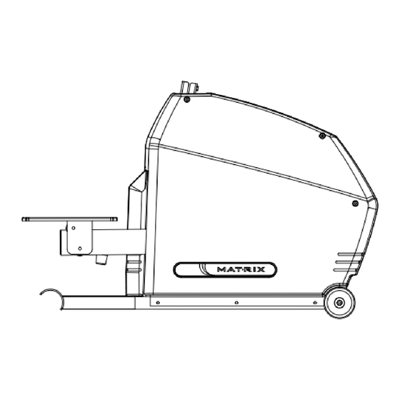
CHAPTER 3: S CHAPTER 4: S erial umber ocation tepper arts and ssembly uides 3.1 SERIAL NUMBER LOCATION 4.1 FASTNERS & ASSEMBLY TOOLS FASTENERS & ASSEMBLY TOOLS The serial number is located in front of right shroud. COLOR PARTS NO. DESCRIPTION QUANTITY SKETCH OF BAG SOCKET BUTTON HEAD BOLT (M8 x 1.25P x 30mm) SPRING WASHER ( 8.2 x 13.5 x 2.0T) SOCKET CAP HEAD BOLT (M8 x 1.25P x 20mm) SOCKET CAP HEAD BOLT... -
Page 5: Exploded Diagram
CHAPTER 4: S CHAPTER 4: S tepper arts and ssembly uides tepper arts and ssembly uides 4.2 EXPLODED DIAGRAM 4.3 ASSEMBLY STEPS STEP 1 STEP 2 Z03 Z01 1) Install the rear foot in position at the rear of the stepper with the mat- ing holes in the frame bracket. Insert the two bolts (Z11) and washers (Z09) through the frame bracket and rear foot. Using the #5 L-type Allen Wrench (Z32) tightens the screws securely. 1) Thread the Console Mast through the Console Mast Boot. 2) Feed the cable through the Console Mast. Tape the cable to the top of the Console Mast to secure it temporarily. 3) Attach the Console Mast to the Base Frame using the bolts (Z01, Z02) and washers (Z03). Ask your assistant to hold the Console Mast while tighten screws. Using the #6 L-type Alen Wrench (Z33) tightens the screws securely. - Page 6 CHAPTER 4: S CHAPTER 4: S tepper arts and ssembly uides tepper arts and ssembly uides 4.3 ASSEMBLY STEPS 4.3 ASSEMBLY STEPS STEP 3 STEP 4 1) Feed the heart rate wires of the handlebar through the small hole located in the back of the Console Mast. Pull these wires up through the hole at the top of the Console Mast. Attach the handlebar to the console mast using two bolts (Z04) and one belt (Z06) for tightening. ASSEMBLY COMPLETE 1) Attach the lower handle supports to the rear foot using the four bolts (Z11) and washers (Z09). Assembly is complete. Tighten with the #5 Allen Wrench (Z32). Final assembly and optional entertainment shown. 2) Install the upper handle supports to the lower handle supports by using the four bolts (Z05) and washers (Z10). Tighten up all bolts in this step with the #5 Allen Wrench (Z32). And, insert the left and right upper handle supports together.
-
Page 7: Chapter 5: Overlay Description / Engineering Mode
CHAPTER 5: O CHAPTER 5: O verlay escription nGineerinG verlay escription nGineerinG 5.1 CONSOLE DISPLAY 5.2 WORKOUT PARAMETER PROMPTS This section lists the default value and value range of workout parameters appeared in the PROMPT AREA, located in the bottom of WORKOUT PROFILE WINDOW. Before an exercise session, each parameter prompt will appear here depending on different programs. PROMPT DEFAULT MINIMUM MAXIMUM UNIT TIME minute LEVEL WEIGHT 68 / 150 34 / 75 182 / 400 kg / lbs years old DISTANCE 5 / 3 1 / 1 80 / 50 km / mile CALORIES... -
Page 8: Workout Overviews
CHAPTER 5: O CHAPTER 5: O verlay escription nGineerinG verlay escription nGineerinG 5.3 WORKOUT OVERVIEWS 5.3 WORKOUT OVERVIEWS This chart lists the Matrix Stepper’s pre-programmed workouts. PROGRAM PROGRAM DEFAULT PROMPT DEFAULT PROMPT DEFAULT PROMPT DEFAULT PROMPT PROGRAM PROGRAM DESCRIPTION DESCRIPTION DESCRIPTION DESCRIPTION NAME NAME TIME INPUT TIME INPUT TIME INPUT TIME INPUT NAME NAME Time,... -
Page 9: Workout Tips
CHAPTER 5: O CHAPTER 5: O verlay escription nGineerinG verlay escription nGineerinG 5.4 WORKOUT TIPS 5.5 WORKOUT SETUP STEPS 1) Matrix Fitness strongly recommends seeing your physician for a complete physical examination before beginning any fitness program. Know your physician-recommended heart rate target zone. If, at any time while exercising, you experiences faintness, dizziness, pain, or shortness of breathe, you must INTERVAL + stop immediately. A) HILL INTERVAL 2) To mount the stepper, grasp the front stationary handlebars and place your feet on the pedals. When you are comfortably situated, begin pedaling. To dis- 1) Repeatedly Press the “INTERVAL+” key to select “HILL INTERVAL”, and then press SELECT. mount the elliptical trainer, stop pedaling, grasp the front stationary handlebars and get off the unit. 2) “SELECT LEVEL” using the RIGHT / LEFT ARROW keys, and then press SELECT. 3) “SELECT TIME” using the RIGHT / LEFT ARROW keys, and then press SELECT. 3) It is highly recommended that you always incorporate the warm-up and cool-down period into your workout. Warm-up brings the heart rate into the lower 4) “SELECT WEIGHT” using the RIGHT / LEFT ARROW keys, and then press SELECT. end of the target zone and increases respiration and blood flow to working muscles. Cool-down takes time for a user’s heart rate to return to a resting state 5) Press START to begin the workout. after vigorous exercise and reduces the amount of lactic acid in muscle tissue. B) RANDOM HILL 1) Repeatedly Press the “INTERVAL+” key to select “RANDOM HILL”, and then press SELECT. 5.5 WORKOUT SETUP STEPS 2) “SELECT TIME” using the RIGHT / LEFT ARROW keys, and then press SELECT. 3) “SELECT WEIGHT” using the RIGHT / LEFT ARROW keys, and then press SELECT. -
Page 10: Using Fitness Networking
CHAPTER 5: O CHAPTER 5: O verlay escription nGineerinG verlay escription nGineerinG 5.5 WORKOUT SETUP STEPS 5.6 USING FITNESS NETWORKING The two RJ45 networking ports are equipped in Matrix Stepper S1x. These ports allow the stepper to be connected to a fitness entertainment system and/or a fitness network, such as FitLinxx®. HEART RATE + C-SAFE / CARDIO PORT A) TARGET HR / WEIGHT LOSS The ports are located on the back of the console. The C-SAFE port enables the stepper to upload user workout statistics to a fitness network database. The 1) Repeatedly Press the “HEART RATE+” key to select “TARGET HR” or “WEIGHT LOSS”, and then press SELECT CARDIO port is compatible to entertainment protocol such as Cardio Theater® or BroadcastVision™. 2) “SELECT AGE” using the RIGHT / LEFT ARROW keys, and then press SELECT. 3) “SELECT HR” using the RIGHT / LEFT ARROW keys, and then press SELECT. 4) “SELECT TIME” using the RIGHT / LEFT ARROW keys, and then press SELECT. 5) “SELECT WEIGHT” using the RIGHT / LEFT ARROW keys, and then press SELECT. 6) Press START to begin the workout. C-SAFE B) FIT TEST 1) “SELECT GENDER” using the RIGHT / LEFT ARROW keys, and then press SELECT. 2) “SELECT AGE” using the RIGHT / LEFT ARROW keys, and then press SELECT. 3) “SELECT LEVEL” using the RIGHT / LEFT ARROW keys, and then press SELECT. 4) “SELECT WEIGHT” using the RIGHT / LEFT ARROW keys, and then press SELECT. 5) Press START to begin the workout. -
Page 11: Chapter 6: Manager's Custom Mode
CHAPTER 6: M ’ CHAPTER 6: M ’ anaGer ustom anaGer ustom 6.1 LIST OF MANAGER’S CUSTOM MODE 6.1 LIST OF MANAGER’S CUSTOM MODE The Manager’s Custom Mode allow the club owner to customize the elliptical trainer for the club. CUSTOM DEFAULT MINIMUM MAXIMUM UNIT STEP DESCRIPTION To enter the Manager’s Custom Mode, press and hold down the “LEVEL ARROW keys“ . Continue to hold down these two keys until the INSTRUCTION SETTING CENTER displays “MANAGER MENU”. Accumulated time is not editable, but only for 1. To scroll through the list of Manager’s Custom Mode, use the “LEFT / RIGHT ARROW keys”, or “LEVEL ARROW keys”. The INSTRUCTION CENTER will display, in display. After the machine reaches the turn, each of custom settings. -
Page 12: Chapter 7: Maintenance
CHAPTER 7: M CHAPTER 8: P aintenance roduct pecifications MAINTENANCE Matrix Stepper S1x is built for commercial environment 12 hours a day and seven days a week. However, as a club manager or owner, you are responsible CONSOLE for cleaning and maintaining the unit’s integrity. If you fail to maintain the elliptical trainer as described below, it could affect or void the Matrix limited war- ranty. Workout Profile Window – 7” blue backlit graphic LCD display NOTE: Safety of the equipment can be maintained only if the equipment is examined regularly for damage or wear. Keep the equipment out of use until Display Screen Instruction Center – 14-character red LED alphanumeric display defective parts are repaired or replaced. Pay special attention to parts that are subject to wear, such as display console, console mounting screws, handrails, link arms, pedal arms and pedals. Informational Display – 3 numeric 7-segment display (3 sets) Display Readout 7.1 DAILY INSPECTION... - Page 13 MATrix F i Tness sysT eM s | 1610 L A ndMAr k d ri ve CoT TAge grove wi 53527 UsA To l l Fre e m a t r i x f i t n e ss . co m Fa x 86 6.693.4 863...
Need help?
Do you have a question about the 1-SERIES and is the answer not in the manual?
Questions and answers