Table of Contents
Advertisement
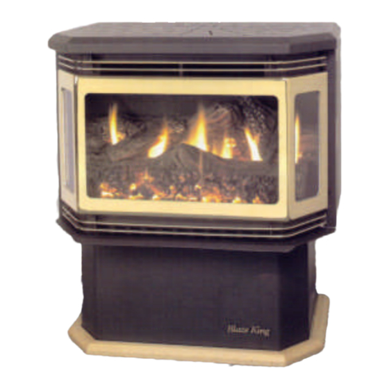
BLAZE KING
Owner's Installation and Operations Manual
INSTALLER: PLEASE LEAVE THIS MANUAL WITH THE CUSTOMER
CUSTOMER: PLEASE KEEP MANUAL FOR FUTURE REFERENCE
WARNING: If the information in these instructions are not followed exactly, a fire or
explosion may result causing property damage, personal injury may result.
- Do not store or use gasoline or other flammable
vapors and liquids in the vicinity of this or any
other appliance.
-WHAT TO DO IF YOU SMELL GAS
Do not try to light any appliance.
Do not touch any electrical switch; do not use any phone in your building.
Immediately call your gas supplier from a neighbor's phone. Follow the gas sup-
plier's
instructions.
If you cannot reach your gas supplier, call the fire department.
Blaze King Industries
146
A St
Walla Walla WA
99362
Ph# 1-509-522-2730
FX# 1-509-522-9803
sales@blazeking.com
Pour la version française de nos manuels S.V.P. vous référez à notre site web :
OM-9603
PRODUCTS
9603R GAS APPLIANCE
This appliance may be installed in an after-
market, permanently located, manufactured
home (USA only) or mobile home, where not
prohibited by local codes.
This appliance is only for use with the type
of gas indicated on the rating plate. This ap-
pliance is not convertible for use with other
gases, unless a certified kit is used.
MANUFACTURED BY
PAGE 1
Valley Comfort Systems Inc.
1290 Commercial Way
Penticton, BC
V2A 3H5
Ph# 1-250-493-7444
FX# 1-250-493-5833
sales@blazeking.com
www.blazeking.com
Date Printed: February 15, 2008
Version: 1.02
Advertisement
Table of Contents

Related Manuals for Blaze King 9603R


Summary of Contents for Blaze King 9603R
- Page 1 BLAZE KING PRODUCTS 9603R GAS APPLIANCE Owner's Installation and Operations Manual INSTALLER: PLEASE LEAVE THIS MANUAL WITH THE CUSTOMER CUSTOMER: PLEASE KEEP MANUAL FOR FUTURE REFERENCE This appliance may be installed in an after- market, permanently located, manufactured home (USA only) or mobile home, where not prohibited by local codes.
- Page 2 Dear Customer: Thank you for purchasing this Blaze King gas appliance. It is our goal to have every purchaser of a Blaze King stove be a satisfied customer. This owner’s manual explains the steps required to safely assemble, install, operate, and maintain your new appliance.
-
Page 3: Table Of Contents
TABLE OF CONTENTS SPECIFICATIONS MODEL 9603 ........................4 SAFETY NOTICE ............................5 COLD WEATHER OPERATION........................5 BLAZE KING’S LIMITED LIFETIME WARRANTY ..................6 WHITE MINERAL DEPOSITS ........................7 COPY OF LABEL............................8 CAUTION ............................... 9 PREPARATION & ASSEMBLY........................9 ELECTRICAL GROUNDING INSTRUCTIONS ................... 10 MOBILE HOME INSTALLATION ....................... -
Page 4: Specifications Model 9603
SPECIFICATIONS* MODEL 9603 GAS APPLIANCE RATING NATURAL GAS LP GAS REAR REAR OUTLET OUTLET OUTLET OUTLET INPUT RATING (BTU/HR) 0-610 m (0-2000 FT.) ALT. 38,000 36,000 38,000 36,000 ORIFICE (DMS) 0-610 m (0-2000 FT.) ALT INPUT RATING (BTU/HR) 610-1370 m (2000-4500 FT.) ALT. (US) * 38,000 34,500 38,000... -
Page 5: Safety Notice
If the combustion, flame pattern, startup or shut down characteristics of your stove change, it could be a sign of ice buildup in the vent system. If this occurs notify your Blaze King Dealer. DO NOT operate your stove if there is excessive ice buildup on the vent cap. -
Page 6: Blaze King's Limited Lifetime Warranty
The combination of these warranty policies provide a very strong coverage package that we are proud to offer you, our customers. Our Blaze King tradition of building high quality products for over 25 years is really your most important assurance of quality but it's nice to know that should something fail (and it occasionally does) you are covered by a warranty policy that leads the industry. -
Page 7: White Mineral Deposits
DOOR SEAL GASKET The front door of your new Blaze King direct vent is gasketed and has been adjusted for a tight seal. As with all direct vent appliances, a tight seal is necessary for maximum performance and proper venting of combustion products. -
Page 8: Copy Of Label
USE DURAVENT TYPE GS TERMINATION CAPS USE DURAVENT TYPE GS TERMINATION CAPS (Must obtain the modified cap from Blaze King) (Must obtain the modified cap from Blaze King) “This appliance is only for use with the type of gas indicated on the rating plate and may be installed in an aftermarket, permanently Tested to ANSI Z21.88b-2007•CSA 2.33b2007”Vented Gas Fireplace Heater”. -
Page 9: Caution
The door assembly must be supplied by Blaze King. Any use of substitute materials is prohibited. The ceramic glass in the door assembly is fragile - Do not abuse, strike or slam the door. -
Page 10: Electrical Grounding Instructions
ELECTRICAL GROUNDING INSTRUCTIONS The power cord on this unit will have a Green wire with a ring (eye) connector on the end of it. This has to be attached to a green screw located on the bottom right of where the fan assembly rests. WARNING - The appliance, when installed must be electrically grounded in accordance with local codes or in the absence of local codes with the National Electrical Code ANSI/NFPA 70- 1987. -
Page 11: Stove Placement Diagram
STOVE PLACEMENT DIAGRAM Canadian Installations US Installations _______________________________________________________________________________________________________________ A= Clearance above grade, veranda *(min. 12”/30 cm) *(min. 12”/30 cm) porch, deck or balcony _______________________________________________________________________________________________________________ B= Clearance to window or door *(min. 12”/30 cm) *(min. 12”/30 cm) that may be opened _______________________________________________________________________________________________________________ C= Clearance to permanently closed *(min. -
Page 12: Spring Tension Lanyard/ Ignition Interlock Safety System
The Spring Tension Lanyard is a simple safety device. It is integrated with the door latch and is not a user serviceable part of the stove. IGNITION INTERLOCK SAFETY SYSTEM Each Blaze King Pegasus direct vent stove comes with a Ignition Interlock Ignition Interlock Safety System. The system was designed to prevent a potentially dangerous gas build up. -
Page 13: Insert Kit Contents
9603 INSERT KIT CONTENTS LOWER LEFT AND RIGHT SHROUDS TOP TRIM MAIN SHROUD - FIG. 27 FIG. 26 OUTER TOP - FIG. 28 WIRE SUPPORT BRACKET FIG. 29 VALVE BRACKET LEFT & RIGHT SIDE COVER PLATES Left & Right Upper Shroud Bracket Tie Wrap X6 #2 Square Drive Screw Strain Relief... - Page 14 9603 INSERT ASSEMBLY INSTRUCTIONS CONTENTS DESCRIPTION PART NUMBER QUANTITY MAIN SHROUD LEFT LOWER SHROUD R8184-L RIGHT LOWER SHROUD R818R LEFT UPPER SHROUD BRACKET R8186-L RIGHT UPPER SHROUD BRACKET R8186-R VALVE BRACKET R8144B WIRE SUPPORT BRACKET R8115A TIE WRAP 0030 LEVELING BOLTS 3/8” 0410 LOCK NUTS 0150...
- Page 15 9603 INSERT ASSEMBLY INSTRUCTIONS 16. Connect the fan and snap disc wires to the rheostat located on the left side of stove. Install rheostat knob. 17. Secure the wires to the wire support bracket using a tie wrap routed through each hole in the bracket. NOTE: IF FAN CORD IS ROUTED ON THE LEFT SIDE, SECURE FAN CORD ALONG WITH RHEOSTAT AND SNAP DISC WIRES.
-
Page 16: Freestanding Kit - Rear And Top Vent
PEGASUS 9603 TOP AND REAR VENT ASSEMBLY Each Blaze King Pegasus 9603 Freestanding comes fully assembled with the exception of the Exhaust Connector and Appliance Adapter. Please follow the simple directions below to complete the venting connection. Vent Connection Assembly Instructions... - Page 17 VENTING REQUIREMENTS The tables below indicate the number of straight section joints allowed when using other vent components. (i.e. elbows, slip joints etc.) 4” and 6” w/o sealant Straight 11 10 10 9 10 8 elbow elbow Adjustable 4” and 6” with sealant on inner (exhaust) joints Straight 57 55 54 53 51 50 54 53 52 50 49 47 52 50 49 48 46 elbow...
-
Page 18: Vent Parts Description
VENT PARTS DESCRIPTION Modified High Wind Horizontal Cap High Wind Cap (BKI #0961) (BKI #0960) Pipe Length Storm Collar Round Support Box/Wall Thimble Flashing 90 Deg. Elbow Ceiling Pipe Length Round Support Box/Wall Thimble Appliance Adapter Exhaust Connector Cathedral Box Modified High Wind 8”... - Page 19 VENT PARTS DESCRIPTION VENT PARTS DESCRIPTION DURA VENT GS AND B.K.I PART NUMBERS AND DESCRIPTIONS DURA VENT GS AND B.K.I PART NUMBERS AND DESCRIPTIONS (MUST USE SIMPSON DURA VENT PIPE) (MUST USE SIMPSON DURA VENT PIPE) 4 x 6 5/8” 4 x 6 5/8”...
-
Page 20: Approved Venting Configurations
APPROVED VENTING CONFIGURATIONS TOP VENT VERTICAL TERMINATION ~OR~ OFFSET VERTICAL TERMINATION (2 - 45 ELBOWS) —33 ft. 5 33 ft. 5 ——— “— ——— ——— —30 ft ——— ——— 30 ft.— ——— ——— ——— — ——— ——— —25 ft. 25 ft.— ———... - Page 21 APPROVED VENTING CONFIGURATIONS CONT. TOP VENT HORIZONTAL TERMINATION ONE 90 ELBOW Min. 17” Horizontal Run 20 3/4” Min. Vertical Rise 33” Max. Horizontal run w/ 20 3/4” min. vertical rise 16 Feet Max. Horizontal Run 16 Feet Max .
- Page 22 APPROVED VENTING CONFIGURATIONS CONT. TOP VENT VERTICAL TERMINATION TWO 90 ELBOWS 31 Feet Max . Vertical rise. (Off top of stove) 16 Feet Max. Horizontal run —33 ft. 5 33 ft. 5 “— ——— ——— ——— ——— —30 ft 30 ft.—...
-
Page 23: Rear Vent
9603 FREESTANDING REAR VENT with Z9625 kit NOTE: The Z9625 Kit reduces the 5" x 8" rear vent down to 4" x 6⅝" REAR VENT VERTICAL OR HORIZONTAL TERMINATION UP TO TWO 90 ELBOWS 8 Feet Minimum Vertical rise. ... - Page 24 APPROVED VENTING CONFIGURATIONS CONT. REAR VENT HORIZONTAL TERMINATION Pegasus Model: 17 Inch minimum Center of pipe is 25” above the surface 42 Inch maximum that the freestanding stove pedestal sits on. This does not include the 5/8” wood base.
-
Page 25: Selkirk Direct-Temp™ Instructions
SELKIRK DIRECT-TEMP™ INSTRUCTIONS INSTALLATION INSTRUCTION APPENDIX FOR BLAZE KING MODEL: 9603-**-NT Selkirk Model Direct-Temp™ direct venting system is now an approved option for the 9603. It has been approved by our safety certification organization, Intertek Testing Services / Warnock Hersey (ITS/WH). -
Page 26: Oak Log Assembly And Ember Placement
OAK LOG INSTALLATION -A- BACK LOG: This larger log should be placed in the back of the stove close to the far back wall. The flat side of (Log A) should rest flush against the flat part of the back bracket with the rough textured side of the log pointing towards you. -
Page 27: Gas Connection
GAS CONNECTION Make sure to follow all state, provincial, and local codes. Blaze King recommends the gas connection be made by a Licensed and qualified installer. The appliance can be connected to the supply line with either rigid or approved flexible gas connection. Check with state, provincial, and local codes. -
Page 28: Clearances To Combustibles
CLEARANCES TO COMBUSTIBLES WARNING ALWAYS REFER TO STATE, PROVINCIAL, AND LOCAL CODES AND VENT MANUFACTURING SPECIFICATIONS FOR SAFE AND EFFICIENT INSTALLATION There is more than 1 option for venting. Make sure chimney is large 18” enough to accept the venting system. -
Page 29: Burner Conversion Instruction
Caution: Before proceeding with the conversion the gas supply must be shut off prior to disconnecting the electrical power. BLAZE KING RECOMMENDS THIS PROCEDURE BE DONE BY QUALIFIED SERVICE PERSONNEL. 1....Remove the 2 screws holding the regulator plate on valve. Remove regulator and gasket. - Page 30 “This conversion kit must be installed Cet èquipement de conversion sera installè by a qualified service agency in agence qualifièe de service accordance with the manufacturer's conformèment instructions instructions and all applicable codes fabricant et toutes exigences et codes and requirements of the authorities applicables l`autorizès avoir...
-
Page 31: Pilot Conversion
38,000 / 36,000 38,000 / 36,000 USE ONLY CONVERSION KITS LISTED BELOW (Model 9603) BLAZE KING PART#’s: NATURAL GAS- Z0739A (Rear Vent/#31main orifice) & Z0740 (Top Vent/1/8” orifice) Note manifold pressures listed above. Read lighting instructions Cycle unit on, back out brass screw a FEW turns in the appropriate pressure test nipple as indicated below. -
Page 32: Orifice Sizing Table
ORIFICE SIZING TABLE Equivalent Orifice Sizes at High Altitudes per the current edition of ANSI Z223.1 (Includes 4% input reduction for each 1,000 feet) NATURAL GAS ORIFICE SIZE REQUIRED AT OTHER ELEVATIONS TOP VENT Orifice size for 9603 at: (Canadian stoves, 2000 ft. - 4500 ft. use #31) Sea Level 2000 3000... -
Page 33: Lighting Instructions
LIGHTING INSTRUCTIONS This unit is equipped with an Ignitor Interlock System. The pilot will not light unless the viewing door is open and the main burner will not light unless the viewing door is closed. 1. STOP! Read the safety information on the previous page. 2. -
Page 34: Starting The Stove For The First Time \ Cleaning Your Unit
Fumes and smoke may come from your stove. This is a result from the paint and oily residue curing and burning off on different parts of the stove and is perfectly normal. Although Blaze King burns each stove at the factory prior to shipment, there may be areas that are not fully cured. -
Page 35: Wiring Diagram
WIRING DIAGRAM - MILLIVOLT NOTE: MILLIVOLT WIRING IS THE SAME FOR HONEYWELL OR ROBERTSHAW, THE TH-TP-TH/ TP LUGS MAY BE IN A DIFFER- ENT ORIENTATION THAN AC WIRING DIAGRAM Snap RHEOSTAT Disc CAUTION F200 When servicing controls label all wires prior todisconnection . Wiring errors can cause Black improper and dangerous... -
Page 36: Replacement Parts List
2. Do not abuse the glass door such as striking or slamming shut. 3. Do not operate the stove with a broken glass door. 4. Do not use abrasive cleaners to clean glass. Call your local BLAZE KING dealer or contact in Canada in the U.S.A. Valley Comfort Systems B.K.I INC. -
Page 37: Notes
Notes: Date Printed: February 15, 2008 OM-9603 PAGE 37 Version: 1.02...
Need help?
Do you have a question about the 9603R and is the answer not in the manual?
Questions and answers