Table of Contents

Related Manuals for Powermatic PM3000


Summary of Contents for Powermatic PM3000
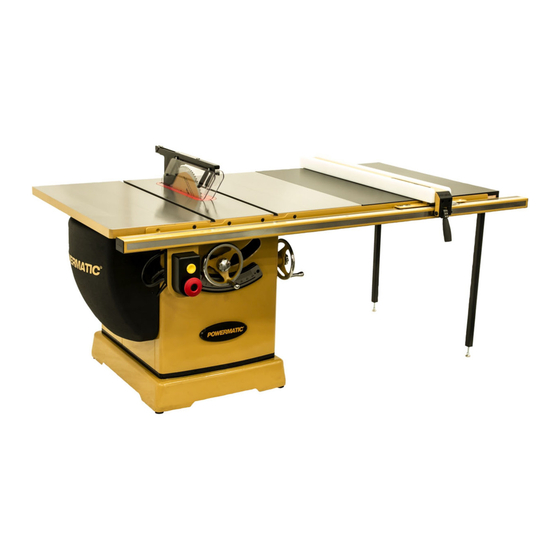
- Page 1 Instructions and Parts Manual 14-inch Cabinet Saw Model PM3000 WMH TOOL GROUP, Inc. 2420 Vantage Drive Elgin, Illinois 60124 Part No. M-1720304 Ph.: 800-274-6848 Revision A2 06/08 www.powermatic.com Copyright © 2008 WMH Tool Group, Inc.
-
Page 2: Warranty And Service
This warranty covers only the initial purchaser of the product. WHAT IS THE PERIOD OF COVERAGE? The general POWERMATIC warranty lasts for the ti m e period specified in the product literature of each product. WHAT IS NOT COVERED? The Five Year Warranty does not cover products used for commercial, industrial or educational purposes. Products with a Five Year Warranty that are used for commercial, industrial or education purposes revert to a One Year Warranty. -
Page 3: Table Of Contents
Table of Contents Warranty and Service..........................2 Table of Contents ..........................3 Warnings............................4 Introduction ............................6 Specifications .............................6 Shipping Contents ..........................7 Unpacking ............................7 Cleaning ............................7 Contents of the Shipping Container ....................7 Mounting Extension Wings .......................9 Lock Knobs and Swivel Handles.......................9 Blade Installation/Replacement ......................10 ... -
Page 4: Warnings
Warnings 1. Read and understand the entire owners manual before attempting assembly or operation. 2. Read and understand the warnings posted on the machine and in this manual. Failure to comply with all of these warnings may cause serious injury. 3. - Page 5 19. Keep visitors a safe distance from the work area. Keep children away. 20. Make your workshop child proof with padlocks, master switches or by removing safety keys. 21. Give your work undivided attention. Looking around, carrying on a conversation and “horse-play” are careless acts that can result in serious injury.
-
Page 6: Introduction
Introduction This manual is provided by WMH Tool Group, Inc. covering the safe operation and maintenance procedures for a Powermatic Model PM3000 Cabinet Saw. This manual contains instructions on installation, safety precautions, general operating procedures, maintenance instructions and parts breakdown. This machine has been designed and constructed to provide years of trouble free operation if used in accordance with instructions set forth in this manual. -
Page 7: Shipping Contents
Contents of the Shipping Container Shipping Contents Main Saw Container Unpacking Table Saw (A) Table Insert (B) Remove box and wood crating completely from around saw. Check for shipping damage. Report Small Box (shown page 8) any damage immediately to your distributor and The following items are inside the saw: shipping agent. - Page 8 Extension Tables Two extension tables are packaged in individual Small Box boxes. The small box consists of the following items: Push Stick (G) 32mm Arbor Wrench (H) Lock Knobs (J) Swivel Handles (K) Riving Knife and Pawl Assembly (L) Hardware Bag (M) consisting of: 3/8-16 x 1 Hex Cap Screws (AA) 3/8 Lock Washer (BB) 3/8 Flat Washer (CC)
-
Page 9: Mounting Extension Wings
Assembly Mounting Extension Wings Referring to Figure 1: 1. Mount a cast iron extension wing (A) to the right or left side of the table (B) using three each 3/8-16x1 hex head screws (C), 3/8 lock washers (D) and 3/8 flat washers (E). Have an assistant hold the extension wing up to the table while you insert the screws and washers. -
Page 10: Blade Installation/Replacement
Blade Installation/Replacement Use care when working with or around sharp saw blade to prevent injury! To install or replace a blade (refer to Figure 5): 1. Disconnect machine from power source. 2. Raise the blade height all the way up and set the blade tilt to 0º... -
Page 11: Motor Cover
Motor Cover Line up the door hinges (A. Figure 7) with the cabinet hinges (B, Figure 7) and insert hinge pins (C, Figure 7). Note: The locking mechanism may require adjustment to insure proper alignment. Riving Knife and Guard Installation Description Referring to Figure 8: The complete riving knife and guard assembly is... -
Page 12: Extension Cords
A power plug is not provided with the Model PM3000. You may either connect the proper UL/CSA listed plug or “hardwire” the machine Figure 9 repeated directly to your electrical panel provided there is a disconnect near the machine for the operator. -
Page 13: Handwheel Adjustments
Adjustments Handwheel Adjustments Referring to Figure 10: The front handwheel (B) controls the raising and lowering of the blade (blade height). The side handwheel (C) controls the blade tilt. The blade can be adjusted for a tilt between 90º (vertical or a setting of 0º on the scale) and 45º left tilt (D). -
Page 14: Miter Slot Alignment
Never use a zero-clearance insert with the saw blade in a tilted position. Never operate the saw without the blade guard, riving knife and anti-kickback pawls for operations where they can be used. When the standard insert is to be used again, the saw blade must be readjusted as follows: 5. -
Page 15: Tilt Stop Adjustment
Tilt Stop Adjustment 1. Adjust the blade tilt for 90º as described in Blade Tilt Adjustment on page 13. 2. Using a combination square, check the 90º stop (Figure 13 shows the 90º stop being checked). 3. Adjust the 90º stop position if required, using the stop screws as shown. -
Page 16: Drive Belt
Extension plate The extension plate (D, Figure 14) can be adjusted by sliding to the right or left or removed entirely. To adjust – loosen two lock handles (E), position the extension plate and tighten the lock handles. remove – slide extension plate completely off and remove the lock handles (E) -
Page 17: Riving Knife Adjustment
Riving Knife Adjustment Lateral alignment The saw blade and riving knife must be in line as close as possible with each other (lateral alignment) for the prevention of kickback. Upon initial blade guard and riving knife installation no further adjustment should necessary. -
Page 18: Insert Adjustment
Referring to Figure 18: 2. With a 5mm hex wrench, loosen two socket head button screws (E). Note: These screws are accessible through openings on the floating clamp block (B) located diagonally on either side of the lock handle (A). They secure the fixed clamp block (C) to the riving knife extension plate (F). -
Page 19: Operations
Operations (NOTE: The following Figure illustrations may or may not show your specific table saw model, but the procedures are identical.) Overview Familiarize yourself with the location and operation of all controls and adjustments and the use of accessories such as the miter gauge and rip fence. - Page 20 Rip Sawing of line with the saw blade and workpiece to avoid sawdust and splinters coming off the blade Ripping is where the work piece is fed with the or a kickback, if one should occur. grain into the saw blade using the fence as a guide and a positioning device to ensure the If the work piece does not have a straight edge, desired width of cut (Figure 24).
- Page 21 Crosscutting should never be done freehand nor When ripping long boards, use a support at the front of the table, such as a roller stand, and a should the fence be used as an end stop unless support or "tailman" at the rear as shown in an auxiliary block is clamped to the front of the Figure 27.
-
Page 22: Bevel And Miter Operations
Figure 32, is necessary for this type of angle less than 90 degrees to the table top operation. [A dado insert for the PM3000, stock (Figure 30). Operations are performed in the no. 1791081, is available from your Powermatic same manner as ripping or crosscutting except dealer.]... -
Page 23: Safety Devices
Safety Devices Feather Board and Push Blocks A push stick is included with the PM3000 table saw. An optional feather board or push block may be purchased by calling customer service at the number shown on the cover and ordering stock number 709721 (feather board) or 708815 (push block). -
Page 24: Maintenance
Mounting bolts air. • Power switch • Wipe down the fence rails with a dry silicon • Saw blade lubricant. • Blade guard assembly Optional Accessories PM3000-282A ... 460V magnetic switch 1791080.... Zero clearance insert, PM3000 1791081.... Dado insert, PM3000... -
Page 25: Troubleshooting
Troubleshooting Trouble Probable Cause Remedy Tilt or raising clamp knobs not Tighten knobs. tightened. Blade out of balance. Change blade. [page 10] Excessive vibration. Bad motor. Replace motor. Loose arbor or motor sheave. Tighten set screws. Miter gauge out of adjustment. Reset pointer. -
Page 26: Replacement Parts
To order parts or reach our service department, call 1-800-274-6848, Monday through Friday (see our website for business hours, www.powermatic.com). Having the Model Number and Serial Number of your machine available when you call will allow us to serve you quickly and accurately. - Page 27 10.... TS-0254021 ....Button Head Socket Screw........1/4-20x1/2....2 11.... PM2000-114....Scale Base..................1 12.... PM2000-115....Latch Post ..................1 13.... TS-0561021 ....Hex Nut............5/16-18 ......1 14.... PM3000-114....Dust Plate ..................1 15.... TS-0050011 ....Hex Cap Screw ..........1/4-20x1/2....4 16.... TS-0680021 ....Flat Washer............1/4......6 17.... TS-0267021 ....Set Screw ............1/4-20x1/4....5 18.... PM3000-118....Table Insert ..................1 19....
-
Page 28: Trunnion & Motor Assembly
Trunnion & Motor Assembly... -
Page 29: Trunnion & Motor Assembly Parts List
....PM2000-RCA ..Running Capacitor (not shown)......35µF, 450VAC....1 ....PM2000-SCCA ..Staring Capacitor Cover (not shown)............1 ....PM3000-JBA ...Junction Box (not shown) ..............1 ....PM3000-JBC ...Junction Box Cover (not shown) ............1 ....PM3000-244A ..Motor ............7-1/2HP, 230/460V, 3Ph ..1 ....PM3000-MFA ..Motor Fan (not shown) ................1 .... - Page 30 56.... PM3000-256....Arbor Nut ...................1 57.... PM3000-257....Arbor Collar ..................1 58.... PM2000-263....Spring ....................1 59.... PM3000-259....Arbor ....................1 ....PM3000-AA.....Arbor Assembly (Index #56, #57, #59, #73 thru #75) 60.... PM3000-260....Fixed Plate ..................1 61.... PM3000-261....Riving Knife Extension Plate..............1 62.... PM2000-267....Clamping Block .................1 63.... PM2000-268....Clamping Block ..................1 64....
-
Page 31: Motor Cover Assembly
Motor Cover Assembly Index No. Part No. Description Size ....6827044....PM2000 Motor Cover Assembly (Index #1 thru #9) .......1 1....PM2000-401....Cover....................1 2....PM2000-402....Hinge Pin ...................2 3....PM2000-403....Bracket ....................1 4....PM2000-404....Latch Clip...................1 5....PM2000-405....Button Head Socket Screw........1/4-20x1-1/4....1 6....TS-0640071 ....Nylon Insert Lock Nut........1/4-20 ......1 7.... - Page 32 Blade Guard & Miter Gauge Assembly...
- Page 33 13.... PM2000-313....Roll Pin ............5x25 ......1 14.... PM2000-314....Roll Pin ............5x12 ......2 15.... PM2000-315....Lock Pin.....................1 16.... PM2000-316....Roll Pin ............4x30 ......1 ....PM3000-AKPA ..Anti-Kickback Pawl Assembly (Index #17 thru 20, 22, 44) .....1 17.... PM3000-317....Anti-Kickback Pawl ................2 18.... PM2000-318....Pawl Base..................1 19.... PM2000-319....Flange ....................2 20....
-
Page 34: Electrical Connections - 5Hp 1 Phase 230V
Electrical Connections – 5HP 1 Phase 230V... -
Page 35: Electrical Connections - 7.5Hp 3Ph 230V
Electrical Connections – 7.5HP 3PH 230V Magnetic Switch Electrical Board WHITE YELLOW BLACK Motor... -
Page 36: Electrical Connections - 7.5Hp 3Ph 460V
Electrical Connections – 7.5HP 3PH 460V Magnetic Switch Electrical Board WHITE YELLOW BLACK Motor WMH Tool Group, Inc. 2420 Vantage Drive Elgin, Illinois 60124 Phone: 800-274-6848 www.powermatic.com www.wmhtoolgroup.com...
Need help?
Do you have a question about the PM3000 and is the answer not in the manual?
Questions and answers