Table of Contents
Advertisement
Quick Links
Advertisement
Table of Contents

Related Manuals for Powermatic PM3000BT


Summary of Contents for Powermatic PM3000BT
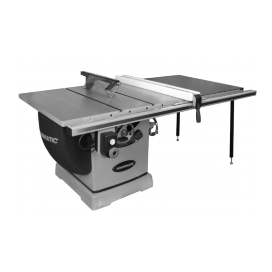
- Page 1 Operating Instructions and Parts Manual 14-inch Cabinet Saw Model PM3000B & PM3000BT Powermatic 427 New Sanford Road LaVergne, Tennessee 37086 Part No. M-PM3753B Ph.: 800-274-6848 Edition 5 04/2023 www.powermatic.com Copyright © 2017 Powermatic...
-
Page 2: Important Safety Instructions
19. Keep visitors a safe distance from the work injury that may result from that use. area. Keep children away. 6. Model PM3000BT has an industrial-grade low- 20. Make your workshop child proof with padlocks, friction corrosion-resistant coating on the table master switches or by removing safety keys. - Page 3 27. Keep hands clear of the blade area. Do not kickback, the high-speed expulsion of material from reach past the blade to clear parts or scrap the table that can strike the operator. Kickback can with the saw blade running. Never saw also result in the operator’s hands being pulled into freehand.
-
Page 4: Table Of Contents
14.3.1 Blade Guard Assembly – Exploded View ..................36 14.3.2 Blade Guard Assembly – Parts List ....................37 14.4.1 PM3000B Miter Gauge Assembly – Exploded View ................38 14.4.2 PM3000B Miter Gauge Assembly – Parts List .................. 39 14.5.1 PM3000BT Miter Gauge Assembly – Exploded View ............... 40... - Page 5 14.5.2 PM3000BT Miter Gauge Assembly – Parts List ................41 14.6.1 Motor Cover Assembly – Exploded View ..................42 14.6.2 Motor Cover Assembly – Parts List ....................42 15.0 Electrical Connections ..........................43 15.1 Wiring Diagram – 7.5HP, 230V, 3PH ....................43 15.2 Wiring Diagram –...
-
Page 6: About This Manual
Additional knowledge can be obtained from experienced users or trade articles. Whatever accepted methods are used, always make personal safety a priority. If there are questions or comments, please contact your local supplier or Powermatic. Powermatic can also be reached at our web site: www.powermatic.com. -
Page 7: Specifications
4.0 Specifications Table 1 Model number PM3000B & PM3000BT Saw only PM3753B & PM3753BT Stock numbers Saw with 50” rip, wood ext. table PM375350K & PM375350KT Motor and Electricals Motor type Totally enclosed, fan cooled, induction Horsepower 7-1/2 HP Motor phase... - Page 8 = not applicable The specifications in this manual were current at time of publication, but because of our policy of continuous improvement, Powermatic reserves the right to change specifications at any time and without prior notice, without incurring obligations.
-
Page 9: Terminology
Featherboard: Device used to keep a board operation. (Powermatic table saws use the superior against the rip fence or table that allows the riving knife system instead.) operator to keep hands away from saw blade. -
Page 10: Setup And Assembly
6.0 Setup and Assembly Note: A ratchet wrench with sockets will speed assembly time. Additional tools may be needed for assembly of fence and rails. Read and understand all assembly instructions before attempting assembly. must disconnected (unplug!) from power during assembly. -
Page 11: Unpacking And Cleanup
Do not use solvents on plastic parts and avoid using an abrasive pad as it may scratch surfaces. Note: Model PM3000BT has an industial-grade low-friction corrosion- resistant coating on the table top and table extensions and will not require cleaning. -
Page 12: Handwheel, Knobs, Levers
Method 2 (Figure 6-5): The switch bracket is installed at the same time as guide tube. Use two screws with washers which 1. Follow steps 1 through 3 from Method 1. are provided with the rails. 2. Position clamps over seam, one at front, one at back of table. -
Page 13: Installing And Removing Blades
If insert is not flush along its length, turn any of 6 set screws to raise or lower that area of insert. Model PM3000BT has an industrial-grade low-friction corrosion-resistant coating on the table and table extensions. -
Page 14: Dust Port
4. Slide prongs of riving knife (M) into slot on Make sure internal hose is pushed into external clamping base, and push riving knife down as dust port (Figure 6-11). Attach hose from your dust far as it will go. collection system to the 4-inch dust port at base of saw, and secure with wire hose clamp (not 5. -
Page 15: Voltage Conversion
equipment-grounding conductor. repair Power Indicator Light – The start switch has a replacement of the electric cord or a plug is power indicator lamp which is on whenever there necessary, connect equipment- is power connected to the saw, not just when the grounding conductor to a live terminal. -
Page 16: Adjustments
Setting Miter Angle (model PM3000B) 8.0 Adjustments The miter gauge has rack and pinion adjustment for setting angle. To operate: Model PM3000BT has an industrial-grade low-friction corrosion-resistant 1. Slide miter gauge into table slot. coating on the table and table extensions. -
Page 17: Blade Tilt Stop Adjustment
7. If the above procedure does not satisfactorily Adjusting Miter Gauge Angle for align the miter gauge, loosen two screws (R, Operations (model PM3000BT, refer to Figure 8-3) beneath mounting block and shift Figure 8-3C): block as needed. Retighten screws when finished. -
Page 18: Riving Knife Alignment
2. Make sure table insert has been leveled with table surface (sect. 6.8). 3. Raise blade to highest position and place a square on table and against blade (Figure 8- 4). Make sure that a blade tooth does not obstruct the actual reading. 4. - Page 19 8.6.2 Blade Proximity Alignment now. If cuts become inaccurate, check table/blade squareness and correct if necessary. The gap between saw blade and riving knife must 1. Disconnect saw from power source. be between 3mm (0.12in.) and 8mm (0.32in.). See Figure 8-9. 2.
-
Page 20: Belt Adjustment
8.8 Belt Adjustment will come to rest approximately 1/8" below table surface when blade is at lowest position. 8.8.1 Belt Tension In situations where a zero-clearance insert is See Figure 8-12. desired, the saw blade may be lowered further for accommodation of inserts that have potential Drive belt tension should be inspected after the first clearance issues with the blade. -
Page 21: Operations
Dull, badly set, improper, or improperly filed Model PM3000BT has an cutting tools, and cutting tools with gum or industrial-grade low-friction corrosion-resistant resin adhering to them can cause accidents. - Page 22 Never rip workpieces shorter than the saw in a location such that the pushing hand is in line blade diameter. with the blade. Move the hand serving as a hold- Never reach behind the blade with either down a safe distance from blade as cut nears hand to hold down or remove the cutoff piece completion.
- Page 23 to stabilize the workpiece and provide operator gauge. Always use the saw guard and riving knife safety. and make sure the riving knife is properly aligned. Narrow boards up to 3" can be resawn in one pass. Wider boards up to 6" must be resawn in two passes.
-
Page 24: Safety Devices
9.5 Bevel and Miter Operations 9.6 Dado Cutting Bevel Cut – A bevel cut is a special type of Dadoing is cutting a wide groove into a workpiece operation where the saw blade is tilted at an angle or cutting a rabbet along the edge of a workpiece. less than 90-degrees to the table top (Figure 9-10). -
Page 25: Push Stick And Push Block
feather board for adjustment. (The illustration shows a method of attaching and use of the feather board as a vertical comb. The horizontal application is essentially the same except that the attachment is to the table top.) Figure 9-13: feather board 10.2 Push Stick and Push Block The use of a push block or push stick provides an added level of safety for the operator. -
Page 26: Maintenance
12.0 Optional Accessories These accessory items (purchased separately) can enhance the functionality of your table saw. Contact your dealer to order, or call Powermatic at the phone number on the cover. Additional accessories may be available; see our website. # 1791081B – Dado Insert... -
Page 27: Troubleshooting
13.0 Troubleshooting 13.1 Motor and Electrical Problems Symptom Probable Cause Remedy Saw will not start. No incoming power. Check plug connection. Safety key removed from switch. Install safety key. Low voltage. Check power line for proper voltage. Open circuit in motor or loose Inspect all connections on motor for loose or connection. -
Page 28: Replacement Parts
Replacement parts are listed on the following pages. To order parts or reach our service department, call 1- 800-274-6848 Monday through Friday (see our website for business hours, www.powermatic.com). Having the Model Number and Serial Number of your machine available when you call will allow us to serve you quickly and accurately. - Page 29 14.1.1 Table and Cabinet Assembly – Exploded View...
- Page 30 3 ....TS-1550071 ....Flat Washer ............. 10 x 20 x 2.0T ..... 10 4 ....PM3000B-104 .... Extension Table (for PM3000B) ..............2 ....PM3000B-104T ..Extension Table (for PM3000BT) ..............2 5 ....PM3000B-105 .... Table (for PM3000B) ..................1 ....
- Page 31 ....LM000304 ....Warning Label ....................1 ....LM000306 ....ID Label, PM3000B ..................1 ....LM000306T ....ID Label, PM3000BT ..................1 ....CL-HV ......Caution Label - High Voltage ................ 2 ....PM2000B-1133 ..Black Stripe ............. 1” W ....... per ft.
-
Page 32: Motor And Trunnion Assembly I - Exploded View
14.2.1 Motor and Trunnion Assembly I – Exploded View... -
Page 33: Motor And Trunnion Assembly Ii - Exploded View
14.2.2 Motor and Trunnion Assembly II – Exploded View... -
Page 34: Motor And Trunnion Assembly - Parts List
14.2.3 Motor and Trunnion Assembly – Parts List Index No Part No Description Size 1 ....TS-1541031 ....Nylon Lock Hex Nut ..........M8-1.25 ......1 2 ....F006042 ..... C-Retaining Ring, Ext ..........STW-14 ......1 3 ....PM2000B-203 .... Compression Spring ..................1 4 .... - Page 35 Index No Part No Description Size 61 ....F010418L ....Soc Set Screw CPP w/thrdlckr ........ M10-1.5 x 25L ....1 62 ....PM3000B-262 .... Motor.............7.5HP 230/460V 60Hz 3PH ..1 ....PM2000B-260AF ..Fan ........................ 1 ....PM2000B-260AFC ..Fan Cover ...................... 1 ....
-
Page 36: Blade Guard Assembly - Exploded View
14.3.1 Blade Guard Assembly – Exploded View... -
Page 37: Blade Guard Assembly - Parts List
14.3.2 Blade Guard Assembly – Parts List Index No Part No Description Size ....PM3000B-BGA ..Blade Guard Assembly (includes #1 thru 18) ..........1 1 ....TS-1541021 ....Nylon Lock Hex Nut ..........M6-1.0 ......8 2 ....PM3000B-302 .... Blade Guard Side Shield ................2 3 .... -
Page 38: Pm3000B Miter Gauge Assembly - Exploded View
14.4.1 PM3000B Miter Gauge Assembly – Exploded View... -
Page 39: Pm3000B Miter Gauge Assembly - Parts List
14.4.2 PM3000B Miter Gauge Assembly – Parts List Index No Part No Description Size ....PM2000B-MGA ..Miter Gauge Assembly (includes #28 thru 49) ..........1 28 ....PM2000B-326 .... Knob ......................1 29 ....TS-1550061 ....Flat Washer ............. 8.5 x 23 x 2.0T ....1 30 .... -
Page 40: Pm3000Bt Miter Gauge Assembly - Exploded View
14.5.1 PM3000BT Miter Gauge Assembly – Exploded View... -
Page 41: Pm3000Bt Miter Gauge Assembly - Parts List
14.5.2 PM3000BT Miter Gauge Assembly – Parts List Index No Part No Description Size ....PM2000B-MGAT ..Miter Gauge Assembly (includes #1 thru 24) ..........1 1 ....PM1500-109T-01 ..Gauge Plate Locking Handle ................. 1 2 ....TS-1550061 ....Flat Washer ............. 8.5 x 23 x 2T ....1 3 .... -
Page 42: Motor Cover Assembly - Exploded View
14.6.1 Motor Cover Assembly – Exploded View 14.6.2 Motor Cover Assembly – Parts List Index No Part No Description Size ....6827044B ....Motor Cover Assembly (includes #1 thru 10) ..........1 1 ....PM2000B-401 .... Motor Cover ....................1 2 .... -
Page 43: Electrical Connections
15.0 Electrical Connections 15.1 Wiring Diagram – 7.5HP, 230V, 3PH Power Cable ST 12AWG*4C*2000mm WHITE BLACK GREEN OVERLOAD RELAY MAGNETIC CONTACTOR WHITE BLACK BLACK WHITE GREEN WHITE WHITE... -
Page 44: Wiring Diagram - 7.5Hp, 460V, 3Ph
15.2 Wiring Diagram – 7.5HP, 460V, 3PH Power Cable ST 12AWG*4C*2000mm WHITE BLACK GREEN OVERLOAD RELAY MAGNETIC CONTACTOR WHITE BLACK BLACK WHITE GREEN WHITE WHITE... -
Page 45: Warranty And Service
Powermatic sells through distributors only. The specifications listed in Powermatic printed materials and on the official Powermatic website are given as general information and are not binding. Powermatic reserves the right to effect at any time, without prior notice, those alterations to parts, fittings, and accessory equipment which they may deem necessary for any reason whatsoever. - Page 46 NOTES...
- Page 47 NOTES...
- Page 48 427 New Sanford Road LaVergne, Tennessee 37086 Phone: 800-274-6848 www.powermatic.com...
Need help?
Do you have a question about the PM3000BT and is the answer not in the manual?
Questions and answers