Table of Contents
Advertisement
Quick Links
Download this manual
See also:
Owner's Manual
Deze download wordt u aangeboden door Pick-upnaalden.nl
Fazantendreef 17-19
8251 JR Dronten
T: 0321 769022
E: info@pick-upnaalden.nl
W: www.pickupnaalden.com
W: www.pickupnaald.com
Facebook: www.facebook.com/pickupnaalden
Twitter: twitter.com/Pickupnaalden
Google+ : plus.google.com/114738445546162436900
Advertisement
Table of Contents

Related Manuals for Denon DP-A100


Summary of Contents for Denon DP-A100
- Page 1 Deze download wordt u aangeboden door Pick-upnaalden.nl Fazantendreef 17-19 8251 JR Dronten T: 0321 769022 E: info@pick-upnaalden.nl W: www.pickupnaalden.com W: www.pickupnaald.com Facebook: www.facebook.com/pickupnaalden Twitter: twitter.com/Pickupnaalden Google+ : plus.google.com/114738445546162436900...
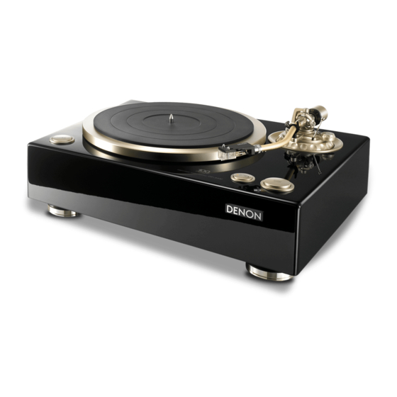
- Page 2 MODIFICATION NOTICE. SERVICE MANUAL MODEL E1K E1C DP-A100 DIRECT DRIVE TURNTABLE SYSTEM For purposes of improvement, specifi cations and design are subject to change without notice. Please use this service manual with referring to the operating instructions without fail. Some illustrations using in this service manual are slightly different from the actual set.
-
Page 3: Safety Precautions
SAFETY PRECAUTIONS The following check should be performed for the continued protection of the customer and service technician. LEAKAGE CURRENT CHECK Before returning the unit to the customer, make sure you make either (1) a leakage current check or (2) a line to chassis resistance check. -
Page 4: Note For Schematic Diagram
NOTE FOR SCHEMATIC DIAGRAM WARNING: Parts marked with this symbol z have critical characteristics. Use ONLY replacement parts recommended by the manufacture CAUTION: Before returning the unit to the customer, make sure you make either (1) a leakage current check or (2) a line to chassis resistance check. If the leakage current exceeds 0.5 milliamps, or if the resistance from chassis to either side of the power cord is less than 460 kohms, the unit is defective. -
Page 5: Technical Specifications
TECHNICAL SPECIFICATIONS n Turntable section n Total Driving system : Servo system direct drive Power supply : AC 120 V, 60 Hz Power consumption : 10 W Speed : 33–1/3rpm, 45rpm Maximum external dimensions : Wow & fl utter : Less than 0.1 % WRMS With dust cover closed: Starting time : Specifi... - Page 6 DISASSEMBLY • Follow the procedure below in reverse order when reassembling. • If wire bundles are untied or moved to perform adjustment or parts replacement etc., be sure to rearrange them neatly as they were originally bundled or placed afterward. Otherwise, incorrect arrangement can be a cause of noise generation.
- Page 7 3. Main P.W.B. unit and Tone Arm Base (1) Remove 4 screws q from the Main P.W.B. unit. (2) Remove the soldering from the tone arm signal wire connected to the output board. When assembling, solder as indicated on the wiring diagram. (3) Holding the tone arm base down, remove the 3 screws e fi...
-
Page 8: Knob Ass'y
5. KNOB ASS'Y (1) Remove the 2 screws u each fi xing the KNOB ASS'Y fi xing plate. (2) Remove the 3 screws i each fi xing the 33/45 unit P.W.B.. (3) Pull out the KNOB ASS'Y fi xing plate and remove the KNOB ASS'Y. - Page 9 ADJUSTMENT Electrical Adjustment for Wow and Flutter (1) Detach the turntable and turn over the set. (2) Open the bottom cover. (3) Connect a digital volt meter or tester to CN104 (3P) on the Motor P.W.B.. (4) Turn on the power. Set the speed to 33 rpm. (5) Insert a screwdriver into R134 (variable resistor) and adjust so that the absolute values of the two digital volt meters or testers are closest.
-
Page 10: Block Diagram
BLOCK DIAGRAM... -
Page 11: Wiring Diagram
WIRING DIAGRAM 33/45 PCB D.D M OTOR PCB C909 CN901 C901 CN301 CN303 CN302 M A I N PCB POWER PCB GND PCB... -
Page 12: Printed Wiring Boards
PRINTED WIRING BOARDS MAIN P.W.B. UNIT FOIL SIDE COMPONENT SIDE OUTPUT P.W.B. UNIT 33/45 P.W.B. UNIT AC P.W.B. UNIT START/STOP P.W.B. UNIT COMPONENT SIDE COMPONENT SIDE COMPONENT SIDE Lead-free Solder When soldering, use the Lead-free Solder (Sn-Ag-Cu). - Page 13 D.D. MOTOR P.W.B. UNIT COMPONENT SIDE FOIL SIDE Lead-free Solder When soldering, use the Lead-free Solder (Sn-Ag-Cu).
-
Page 14: Schematic Diagrams
C103 102P 405-TT300-753 IC901 IC902 R106 R107 D105 NJM7805 NJM7812 1SS133 Q103 C110 C119 2SD1889 C114 0.1uF 100u/35 C101 102P 100u/35 D106 1SS133 IC101B R101 6.8K R102 NJM2147 D101 C102 102P R122 1 1W R105 270 1SS133 R104 Q104 CN903A D104 C118 2SB1340... - Page 15 MAIN UNIT R327 C311 IC301 R317 C313 C310 C312 4.7K 100u/10 R302 R304 0.1uF R306 R314 L302 C307 C309 3.3K R305 1M R321 X301 C302 R303 16MHz 0.1uF BD4745G 0.1uF 1u/50 D301 R322 R301 1SS132 IC302A R307 BA10393 C314 C301 C315 100u/10 C303...
- Page 16 EXPLODED VIEW s for E3 for E2 WARNING: Parts marked with this symbol have critical characteristics. Use ONLY replacement parts recommended by the manufacturer.
- Page 17 POINTS OF GREASING s Grease:KF-96H Around inner of indicator (no leakage on the sueface) ( 30mg <Φ3.5> ) Grease:CR-S Around inner of indicator (no leakage on the sueface) ( 15mg <Φ3> Grease:CR-S Shaft all area (4.0mg <Φ2> each X 2 ) Grease:CR-S Shaft all area ( 4.0mg <Φ2>...
- Page 18 PARTS LIST OF EXPLODED VIEW s zParts for which "nsp" is indicated on this table cannot be supplied. zP.W.B. ASS'Y for which "nsp" is indicated on this table cannot be supplied. When repairing the P.W.B. ASS'Y, check the board parts table and order replacement parts. zPart indicated with the mark "...
- Page 19 406-1300-698 GROUNDING METAL NET 407-DJ1900-094 00MYT02011280 VFS RCA PIN JACK (RED) 420-A100-346 00MYT02011290 VFS RCA PIN JACK (WHITE) 420-A100-347 VFS CARTRIDGE(DL-A100) 402-A100-100 941421003660D DENON BADGE 501-A100-2363 1P WIRE (L50,RED) 406-A100-1152 1P WIRE (L50,YEW) 406-A100-1153 CAUTION LABEL 501-A100E2-2380 FCC LABEL 501-A100E3-2382...
- Page 20 PACKING VIEW s -1~7 -1~3 -1~2 for E3 -1~2 for E2 -1~2 -1~7 -1~2 -1~2 -1~3...
-
Page 21: Warranty
PARTS LIST OF PACKING VIEW s z Parts for which "nsp" is indicated on this table cannot be supplied. z Part indicated with the mark " " is not illustrated in the exploded view. z The parts listed below are for maintenance only, might differ from the parts used in the unit in appearances or dimensions. Note: The symbols in the column "Remarks"... -
Page 22: Pin Description
SEMICONDUCTORS Only major semiconductors are shown, general semiconductors etc. are omitted to list. The semiconductor which described a detailed drawing in a schematic diagram are omitted to list. 1. IC's MAX003 (IC303) AVCC VREF P70/AN0 P71/AN1 P72/AN2 P73/AN3 P74/AN4 P75/AN5 P76/AN6/DA0 P77/AN7/DA1 AVSS... - Page 23 NJM-2147D (IC101,102) OUT1 -IN1 OUT2 -IN2 +IN1 +IN2 HEDS9700F51 (IC103)
- Page 24 US1881 (H11-H13) DTC124TS U 1 8 1 3 5 P I N O U T : (3) Base (2) Collector P in 1 Pin 2 G N D (1) Emitter Pin 3 O u t p u t 2SB1340 B : Base C : Collector E : Emitter 2SD1889...
- Page 25 PARTS LIST OF P.W.B. UNIT s Parts for which "nsp" is indicated on this table cannot be supplied. The parts listed below are for maintenance only, might differ from the parts used in the unit in appearances or dimensions. Note: The symbols in the column "Remarks" indicate the following destinations. E3 : U.S.A.
- Page 26 Ref. No. Part No. Part Name Remarks Q'ty R328 CARBON FILM RESISTOR(220 OHM J 1/6W) 412-3113-058 R329 CARBON FILM RESISTOR(470 OHM J 1/6W) 412-3113-056 R330 CARBON FILM RESISTOR(470 OHM J 1/6W) 412-3113-056 R331 CARBON FILM RESISTOR(10K OHM J 1/6W) 412-3113-068 R332 CARBON FILM RESISTOR(10K OHM J 1/6W) 412-3113-068...
- Page 27 DC&33/45&START/STOP PCB UNIT ASS'Y Ref. No. Part No. Part Name Remarks Q'ty SEMICONDUCTORS GROUP IC901 00D9580040303 IC 7805 417-KC730-123 IC902 00D9410022103 IC(7812) 417-BJ1900L-231 D201 00D9410023102 LED(LTL1CHKFKNN) 410-1300-243 D202 00D9410023209 LED(LTL1RMTGK) 410-1300-244 OTHER PARTS GROUP CN201 4P2.0 CONNECTOR WIRE(L=140mm) 404-1300-1678 CN202 2P CONNECTOR WIRE(L=150mm) 404-HDJ7100-760 CN903A...
- Page 28 D.D MOTOR PCB UNIT ASS'Y Ref. No. Part No. Part Name Remarks Q'ty SEMICONDUCTORS GROUP IC101 00D9410021104 IC(NJM-2147D,DIP-8) 417-DJ5500-579 IC102 00D9410021104 IC(NJM-2147D,DIP-8) 417-DJ5500-579 IC104 00D9410021609 IC(NJM-4580M-TE2,SOP-8) 417-ST150-599 IC105 00D9410021609 IC(NJM-4580M-TE2,SOP-8) 417-ST150-599 IC106 00D9410021502 IC(TC4066BFN/BU4066BCF/BU4066BCF-E2) 417-QMX2-190 IC903 00D9410021007 IC(NJM7824) 417-DJ2500-268 IC904 00D9410021201 IC(NJM-7924FA,3PIN) 417-DJ5500-581 IC905...
- Page 29 Ref. No. Part No. Part Name Remarks Q'ty R105 CARBON FILM RESISTOR(270 OHM J 1/6W ) 412-3113-049 R106 CARBON FILM RESISTOR(270 OHM J 1/6W ) 412-3113-049 R107 CARBON FILM RESISTOR(22K OHM J 1/6W ) 412-3113-059 R108 CARBON FILM RESISTOR(6.8K OHM J 1/6W ) 412-3113-069 R109 CARBON FILM RESISTOR(680 OHM J 1/6W )
- Page 30 Ref. No. Part No. Part Name Remarks Q'ty CAPACITORS GROUP C101 CERAMIC CAPACITOR(1000pF/50V,K,Y5P) 413-1430-071 C102 CERAMIC CAPACITOR(1000pF/50V,K,Y5P) 413-1430-071 C103 CHIP CAPACITOR(1000pF/50V,J,0805 TYPE,NPO) 413-DV330-311 C104 CERAMIC CAPACITOR(1000pF/50V,K,Y5P) 413-1430-071 C105 CERAMIC CAPACITOR(1000pF/50V,K,Y5P) 413-1430-071 C106 CHIP CAPACITOR(1000pF/50V,0805 TYPE,NPO) 413-DV330-311 C107 CERAMIC CAPACITOR(1000pF/50V,K,Y5P) 413-1430-071 C108 CERAMIC CAPACITOR(1000pF/50V,K,Y5P) 413-1430-071...
- Page 31 Ref. No. Part No. Part Name Remarks Q'ty C913 ELEC. CAPACITOR(100uF/35V,M,TAPING 8*11) 413-HMD5000-356 C914 CERAMIC CAPACITOR(0.1uF/50V,Z,TAPING,Y5V) 413-3113-035 C915 ELEC. CAPACITOR(100uf/25V,M,TAPING 6.3*11) 413-HS100-180 C916 CHIP CAPACITOR(0.1uF/50V,Z,0805 TYPE,Y5V) 413-DV330-313 C917 ELEC. CAPACITOR(100uf/25V,M,TAPING 6.3*11) 413-HS100-180 C918 00D9410055604 METAL POLYSTER CAPACITOR(0.1uF/AC125V,K) 413-DJ3500-884 C918 CHIP CAPACITOR(0.1uF/50V,Z,0805 TYPE,Y5V) 413-DV330-313 OTHER PARTS GROUP CN102...
Need help?
Do you have a question about the DP-A100 and is the answer not in the manual?
Questions and answers