Table of Contents
Advertisement
Advertisement
Chapters
Table of Contents

Related Manuals for Blue Seal Turbofan E32M


Summary of Contents for Blue Seal Turbofan E32M
- Page 1 E32M CONVECTION OVEN SERVICE MANUAL Revision 1/F3586...
- Page 2 WARNING: ALL INSTALLATION AND SERVICE REPAIR WORK MUST BE CARRIED OUT BY QUALIFIED PERSONS ONLY. Revision 1/F3586...
-
Page 3: Table Of Contents
CONTENTS This manual is designed to take a more in depth look at the E32M and E32MS convection ovens for the purpose of making the units more understandable to service people. There are settings explained in this manual that should never require to be adjusted, but for completeness and those special cases where these settings are required to change, this manual gives a full explanation as to how, and what effects will result. - Page 4 PARTS DIAGRAM ......................40 11.1 Main Assembly 11.2 Control Panel Assembly 11.3 Gear Plate Assembly 11.4 Door Assembly SERVICE CONTACTS ....................47 Revision 1/F3586...
-
Page 5: Specifications
1. SPECIFICATIONS MODEL: E32M (28") (32") (2") FRONT SIDE (2¾") PLAN LEGEND - Electrical connection entry point - Water entry - ¾” BSP hose connection Dimensions shown in millimetres. Dimensions in inches shown in brackets. Revision 1/F3586... - Page 6 MODEL: E32MS (28") (32") (2") FRONT SIDE (2¾") PLAN LEGEND - Electrical connection entry point - Water entry - ¾” BSP hose connection Dimensions shown in millimetres. Dimensions in inches shown in brackets. Revision 1/F3586...
- Page 7 LOCATION To ensure correct ventilation for the motor and controls the following minimum installation clearances are to be adhered to: Rear 40mm / 1.5“ Left-hand side 40mm / 1.5” Right-hand side* 40mm / 1.5” 390mm / 16” * Fixed installations require at least 500mm (20”) clearance at the right hand side for service accessibility.
-
Page 8: Installation
2. INSTALLATION WARNING: THIS APPLIANCE MUST BE GROUNDED. WARNING: ALL INSTALLATION AND SERVICE REPAIR WORK MUST BE CARRIED OUT BY QUALIFIED PERSONS ONLY. Before Connection to Power Supply • Remove all packing. floor mounting or provided with stands are adjustable and will require adjusting in •... - Page 9 Before Use • Operate the oven for about 1 hour at 200°C (400°F) to remove any fumes or odours which may be present. Rating Plate Location The rating plate for the E32M and E32MS convection ovens is located at the bottom front corner of the RH side panel.
-
Page 10: Operation
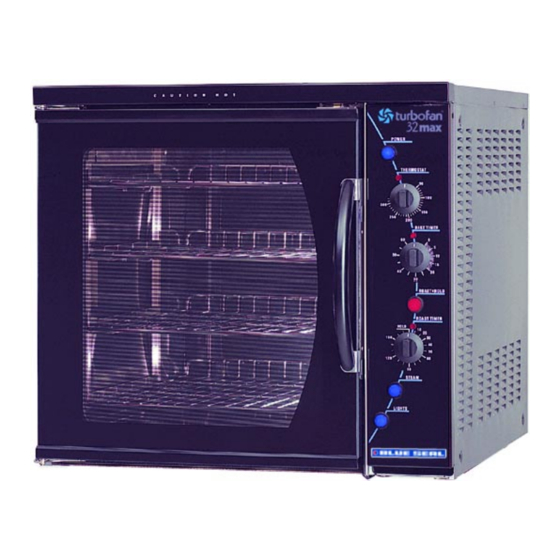
3. OPERATION NOTE: A full user’s operation manual is supplied with the product and can be used for further referencing of installation, operation and service. 3.1 DESCRIPTION OF CONTROLS Power Depress to switch power on or off (switch illuminates when power is on). Thermostat Temperature range 50 - 320°C (120 - 600°F). -
Page 11: Explanation Of Control System
EXPLANATION OF CONTROL The temperature control of this oven is with a SYSTEM capillary type thermostat which can be set to a required cooking temperature. The E32M and E32MS Turbofan convection The control panel indicator light above the ovens feature multi-function operator controls thermostat knob cycles On and Off with the for which a correct understanding of their op- thermostat to indicate when the elements are... - Page 12 the control panel. When the relay is switched The following Troubleshooting Guide should ON a normally closed switch pole on the relay be used to identify any incorrect oven is opened and the normal power supply to the operation. On correct identification of the oven thermostat is isolated.
-
Page 13: Maintenance
4. MAINTENANCE WARNING: ALL INSTALLATION AND SERVICE REPAIR WORK MUST BE CARRIED OUT BY QUALIFIED PERSONS ONLY. 4.1 CLEANING OVEN SEALS WARNING: ALWAYS TURN THE POWER SUPPLY OFF BEFORE To remove, hold at their centre point and CLEANING. pull forward until they unclip. Remove side seals first, then top and bottom. -
Page 14: Routine Procedures
4.2 ROUTINE PROCEDURES PROCEDURE INTERVAL DOOR SEALS Check for deterioration. 12 months DOOR PIVOT BUSHES Check for wear. 12 months DOOR CATCHES Ensure that catches are adjusted such that the door 12 months closes properly. ELEMENT Check that element resistance is correct to it’s rating 12 months (refer 6.3.15). -
Page 15: Trouble Shooting Guide
5. TROUBLE SHOOTING WARNING: ALL INSTALLATION AND SERVICE REPAIR WORK MUST BE CARRIED OUT BY QUALIFIED PERSONS ONLY. FAULT POSSIBLE CAUSE REMEDY THE OVEN DOES NOT The mains isolating switch on Turn on. OPERATE / START the wall, circuit breaker or fuses are “off”... - Page 16 FAULT POSSIBLE CAUSE REMEDY NO WATER INJECTION / Water not turned on. Turn water on at water supply. STEAM Oven water nozzle blocked. Remove, clean or replace. (Refer service section 6.3.14) Fault with water valve. Service or replace as required. (Refer fault diagnosis 6.1.5) (Refer service section 6.3.12, 6.3.13)
- Page 17 FAULT POSSIBLE CAUSE REMEDY SLOW RECOVERY Oven in ‘Roast ‘n Hold’ mode. Switch off ‘Roast ‘n Hold’. Overloading of oven. Reduce oven loading. Electrical supply incorrect. Check supply voltage is as per rating plate voltage. Fan not working. Check fan operation. Thermostat out of calibration.
- Page 18 FAULT POSSIBLE CAUSE REMEDY DOOR SEAL LEAKS Door seal damaged. Replace. (Refer service section 6.3.22) Door seal incorrectly fitted. Correctly install door seal. (Refer service section 6.3.22) Door catch setting incorrect. Adjust. (Refer service section 6.4.3) Door pivot bushes / pins worn. Replace.
-
Page 19: Service Procedures
6. SERVICE PROCEDURES WARNING: ENSURE POWER SUPPLY IS SWITCHED OFF BEFORE SERVICING. WARNING: ALL INSTALLATION AND SERVICE REPAIR WORK MUST BE CARRIED OUT BY QUALIFIED PERSONS ONLY. SECTION PAGE NO. FAULT DIAGNOSIS ......................21 6.1.1 Oven Does Not Operate / Start ................21 6.1.2 Fan Does Not Operate .................. - Page 20 6.3.21 Inner Glass ......................32 6.3.22 Door Seals ......................32 6.3.23 Door Pivot Bushes ....................32 6.3.24 Stainless Steel Door—Outer Glass ..............33 6.3.25 Stainless Steel Door—Inner Glass ..............33 ADJUSTMENT / CALIBRATION ..................34 6.4.1 Thermostat Calibration ..................34 6.4.2 Door Microswitch Adjustment ................
-
Page 21: Fault Diagnosis
6.1 FAULT DIAGNOSIS Fan motor timer faulty With oven switched on, and door closed, ensure that the cams on the motor timer are 6.1.1 OVEN DOES NOT OPERATE / START rotating. Incorrect electrical supply Check that the voltage across phase and neutral (L1 and L2) terminals of terminal block is the voltage as stated on the unit’s electrical Motor... -
Page 22: Oven Light Not Illuminating-Door Open
Check voltage to the bottom terminal of the 6.1.3 OVEN LIGHTS NOT ILLUMINATING - switch. If there is no voltage, then check DOOR OPEN (AUTOMATICALLY ON) wiring. No power to lights With switch depressed, check for voltage at top terminal. If there is no voltage then Check the supply voltage across lamp replace switch. -
Page 23: Minute Timer No Time Up Indicator
Timer not switching on buzzer Hold Relay With timer in zero position, check voltage to top connection (terminal one) and bottom connection (terminal two) of timer. If there is no voltage at terminal one then check wiring. If no voltage at terminal two then timer is Figure 6.1.6 faulty—replace. -
Page 24: No Temperature Control (Temperature Overrun)
Element faulty (blown) 6.1.12 NO THERMOSTAT HEATING INDICATOR With the thermostat on and heating check voltage across element terminals at RH side Indicator faulty of oven. If the voltage is correct then check the current draw of element. If there is no Check the voltage across the indicator current draw then element is faulty—replace. -
Page 25: No Hold Indicator
If the voltage is correct, and the thermostat is ‘Roast ‘n Hold’ switch faulty Check if the switch latches. If the switch does adjusted above oven temperature, then check not latch then the switch is faulty—replace. for output voltage at terminal 1 (bottom) of hold thermostat. -
Page 26: Access
6.2 ACCESS 6.2.3 CONTROL PANEL—REAR 6.2.1 CONTROL PANEL 1) Undo the two screws at the bottom of the Power Switch control panel. Heating Indicator Thermostat Bake Time Up Indicator Buzzer Bake Timer Two screws Figure 6.2.1 Hold Relay 2) The panel can now be removed. When closing the panel ensure wires and Hold Thermostat thermostat capillary tubes are clear of... -
Page 27: Replacement
6.3 REPLACEMENT Neon wires 6.3.1 LIGHT BULB / GLASS 1) Unscrew lamp cover(s). Lamp covers Figure 6.3.3 2) From back push neon through front of panel rotating clockwise. 3) Push new neon in from front of panel, and reconnect wires. Figure 6.3.1 6.3.4 POWER / ROAST / LIGHTS / STEAM 2) Unscrew bulb out of fitting. -
Page 28: Hold Relay
3) Withdraw and remove two screws holding 6.3.8 ROAST TIMER buzzer to bracket. 1) Remove roast timer knob by pulling it 4) Transfer wires to new buzzer. firmly away from control panel. 5) Reassemble in reverse order. 2) Open control panel (refer 6.2.1) and undo two screws securing timer. -
Page 29: Hold Thermostat
5) Withdraw old thermostat phial through 4) Withdraw the old hold thermostat phial side of oven. Note position in phial through the side of the oven. Note the bracket. position of the phial in the bracket. 6) Insert new thermostat. 5) Insert new thermostat phial. -
Page 30: Water Solenoid Cleaning
5) Carefully withdraw solenoid. 6.3.15 ELEMENTS 6) Replace or service solenoid as required. 1) Remove service panel (refer 6.2.2) and 7) To reinstall, reverse procedure. baffle. 8) Check water connections do not leak. 2) Remove the wires from the elements. 9) Check for correct operation of the oven water injection. -
Page 31: Motor
6.3.17 MOTOR Capacitor 1) Remove fan (refer 6.2.16). 2) Remove the right hand service panel and then remove the motor wires. 3) Undo the four screws holding the motor in place (from inside the oven) and remove motor. Four Figure 6.3.22 screws 3) Remove the capacitor wires, noting their positions. -
Page 32: Inner Glass
4) Remove four screws in top trim and four screws in bottom trim of door, and remove trim panels. Four screws Door seals Four screws Figure 6.3.27 Figure 6.3.25 3) Refit new seals. 5) Lift outer glass away from door. Note: Fit top and bottom seals first, with 6) To replace, ensure that the two silicone open side of seal facing down-... -
Page 33: Stainless Steel Door-Outer Glass
3) Replace with new glass. 6.3.24 STAINLESS STEEL DOOR - OUTER GLASS Ensure when replacing that the side with the ‘L’ mark is inside the door (not inside 1) Remove the door as per steps one and the oven). This ensures the correct two of section 6.3.20. -
Page 34: Adjustment / Calibration
6.4 ADJUSTMENT / CALIBRATION 6.4.2 DOOR MICROSWITCH ADJUSTMENT 1) Open oven door. 2) Open control panel (refer 6.2.1). 6.4.1 THERMOSTAT CALIBRATION 3) With fingers, bend actuator arm of microswitch so that switch operates when IMPORT ANT: OVEN door is in closed position. T E M P E R A T U R E N E E D S INCREASED,... -
Page 35: Door Roller Catch Adjustment
5) If necessary the roller catches can be 6.4.6 HOLD TEMPERATURE ADJUSTMENT removed from the door (after removing handle on stainless steel doors) to adjust 1) Open control panel (refer 6.2.1) to gain height settings for correction of door catch access to the hold thermostat (located operation. -
Page 36: Electrical Schematics
7. ELECTRICAL CIRCUIT SCHEMATIC BLUE BROWN BLACK Revision 1/F3586 -36-... -
Page 37: Electrical Wiring Diagrams
8. ELECTRICAL WIRING DIAGRAM BROWN BLACK BLUE Revision 1/F3586 -37-... -
Page 38: Spare Parts
9. SPARE PARTS Controls 021473 Power Switch 024774 Thermostat 021472 Knob - Thermostat 020849 Neon Indicator 011760 Bake Timer 011794 Buzzer 021476 Switch- Roast ’n’ Hold 011419 Roast ’n’ Hold Timer 020823 Knob - Bake Timer / Roast ’n’ Hold Timer 021474 Steam Switch 024773... -
Page 39: Accessories / Options
10. ACCESSORIES OVEN RACKS (PART NO 15168) DOUBLE STACKING KIT (PART NO 025012) 100 MM (FOUR INCH) FOOT OPTION (PART NO 13048) 25 MM (ONE INCH) FOOT OPTION (PART NO 13908) A25 STAINLESS STEEL STAND COOKIE KIT—SIX TRAY OPTION (PART NOS 17156 & 17157) Revision 1/F3586 -39-... - Page 40 11. PARTS DIAGRAMS 11.1 MAIN ASSEMBLY Revision 1/F3586 -40-...
- Page 41 Part No. Description 024683 SIDE COVER RH --------- GEAR TRAY (REFER SECTION 11.3) 024431 FAN MOTOR 024604 MOTOR MOUNTING PLATE 013520 OVEN LIGHT ASSEMBLY 003434 SILK GASKET 013521 LAMP - 40W 003002 LIGHT GLASS 024717 BAFFLE LOCATING PLATE 024478 FAN SHAFT SEAL 024433 024689 SIDE PANEL MOUNTING BRACKET...
-
Page 42: Control Panel Assembly
11.2 CONTROL PANEL ASSEMBLY 11.2.1 E32M Control Panel Part No. Description 004953 CONTROL PANEL BAKBAR °C 004954 CONTROL PANEL BLUE SEAL °C 021473 POWER SWITCH 020849 INDICATOR LIGHT 021472 THERMOSTAT KNOB 020823 TIMER KNOB 021476 ROAST N HOLD SWITCH 021474... - Page 43 11.2.2 E32MS Control Panel Part No. Description 024805 CONTROL PANEL ST/ST 024775 OVERLAY BAKBAR °C 024776 OVERLAY BLUE SEAL °C 024777 OVERLAY MOFFAT °F 021473 POWER SWITCH 020849 INDICATOR LIGHT 021472 THERMOSTAT KNOB 020823 TIMER KNOB 021476 ROAST N HOLD SWITCH...
- Page 44 11.3 GEAR PLATE ASSEMBLY Part No. Description 024772 GEAR TRAY 014185 MAIN TERMINAL BLOCK 024567 MOTOR TIMER 240V 024503 MOTOR TIMER 220V 015966 CONTACTOR 024432 CAPACITOR 3µF 002441 INSULATOR 002138 CABLE CLAMP Revision 1/F3586 -44-...
- Page 45 11.4 DOOR ASSEMBLY 11.4.1 E32M Glass Door Assembly Part No. Description 024809 ROLLER CATCH ASSEMBLY 004928 DOOR INNER ENAMELLED 024602 DOOR TRIM BOTTOM 090225 GLASS SEAL EXTRUSION (1.14m) 020083 BOTTOM HINGE ASSEMBLY 090200 GLASS SEAL EXTRUSION (1.74m) 024844 DOOR OUTER GLASS 004452 GLASS CLAMP ANGLE PAINTED 002340...
- Page 46 11.4.2 E32MS Stainless Steel Door Assembly Part No. Description 024809 ROLLER CATCH ASSEMBLY 020083 BOTTOM HINGE ASSEMBLY 024605 GLASS CLAMP ANGLE 023063 DOOR WINDOW GLASS 090201 GLASS SEAL EXTRUSION (1.44m) 024845 DOOR OUTER PANEL 090200 GLASS SEAL EXTRUSION (1.44m) 020082 TOP HINGE ASSEMBLY 004957 DOOR INNER (ENAMELLED)
- Page 47 11. SERVICE CONTACTS AUSTRALIA VICTORIA - MOFFAT PTY HEAD OFFICE AND MAIN WAREHOUSE 740 Springvale Road Tel (03) 9518 3888 Mulgrave VIC 3170 Fax (03) 9518 3838 Spare Parts Department Free Call 1800 337 963 Fax (03) 9518 3895 NEW SOUTH WALES - MOFFAT PTY Unit 8/142 James Ruse Drive Rosehill NSW 2142 Spare Parts...
- Page 48 UNITED KINGDOM BLUESEAL LTD Units 6-7 Mount St Tel 0121-327 5575 Business Park Fax 0121-327 9711 Birmingham B7 5QU England UNITED STATES OF AMERICA MOFFAT INC. 3765 Champion Blvd Winston-Salem Tel 1-800-551 8795 NC27115 Fax 336 661 9546 NATIONAL COVERAGE FOR SERVICE OR MAINTENANCE DIAL FREE CALL 1800 551 8795 (USA ONLY) Revision 1/F3586 -48-...
Need help?
Do you have a question about the Turbofan E32M and is the answer not in the manual?
Questions and answers
Does the E32M turbofan oven have a distributor in Indonesia?