Table of Contents
Advertisement
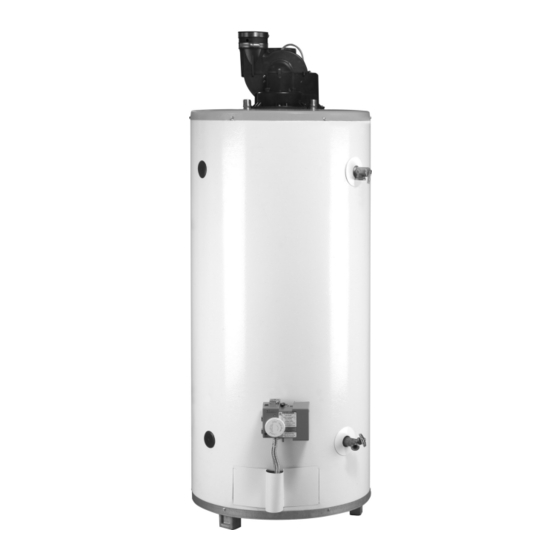
POWER DIRECT VENT WATER HEATER
INSTALLATION AND OPERATING INSTRUCTIONS
Read and understand these instructions thoroughly before starting
WARNING:
Improper installation, adjustment, alter-
ation, service, or maintenance can cause
injury or property damage. Refer to this
manual. For assistance or additional infor-
mation, consult a qualified installer, serv-
ice agency, or the gas utility.
FOR YOUR SAFETY
• Do not store or use gasoline or other
flammable vapours and liquids in the
vicinity of this or any other appliance.
• Installation and service must be per-
formed by a qualified installer, service
agency or the gas utility.
WARNING:
If the information in these instructions is
not followed exactly, a fire or explosion
may result causing property damage, per-
sonal injury or death.
WHAT TO DO IF YOU SMELL GAS
• Do not try to light any appliance.
• Do not touch any electrical switch; do
not use any phone in your building.
• Immediately call your gas supplier from
a neighbor's phone. Follow the gas
supplier's instructions.
• If you cannot reach your gas supplier,
call the fire department.
GSW Water Heating is a division of
A. O. Smith Enterprises Ltd.
PART NO. 186723-000 REV. B (08-07)
Advertisement
Table of Contents

Related Manuals for John Wood 4040SN-PDV


Summary of Contents for John Wood 4040SN-PDV
- Page 1 • Immediately call your gas supplier from a neighbor’s phone. Follow the gas supplier’s instructions. • If you cannot reach your gas supplier, call the fire department. PART NO. 186723-000 REV. B (08-07) GSW Water Heating is a division of A. O. Smith Enterprises Ltd.
- Page 2 This page intentionally left blank. May be used for notes or to record other installation information. – 2 –...
-
Page 3: Table Of Contents
TABLE OF CONTENTS I) INTRODUCTION ......4 V) OPERATION ......26 User Responsibilities Water Heater Operation II) SAFETY. -
Page 4: I) Introduction
I) INTRODUCTION FAILURE TO FOLLOW THE INSTRUCTIONS IN THIS MANUAL MAY RESULT IN SERIOUS BODILY INJURY Thank you for purchasing a GSW Power Direct Vented AND/OR PROPERTY DAMAGE. THOROUGHLY READ Water Heater. Properly installed and maintained, it will pro- AND UNDERSTAND ALL INSTRUCTIONS BEFORE YOU vide years of trouble free service. -
Page 5: Ii) Safety
Safety Warning (Flammable Vapours) Service to the Power Direct Vent System should only be performed by a qualified service technician. WA R N I N G The manufacturer and seller of this water heater will not assume any liability for any property damage, personal injury or death resulting from improper sizing, installation or failure to comply with these instructions. -
Page 6: Relief Valve Requirements (T&P)
GSW technician. WILL NOT ASSUME ANY LIABILITY for damage caused... -
Page 7: Clearances And Accessibility
Gas Supply • The water heater should be located in an area not sub- ject to freezing temperatures. Water heaters located in DANGER unconditioned spaces (i.e., attics, basements, etc.) may require insulation of the water piping and drain piping to protect against freezing. -
Page 8: Gas Pressure
Venting 1. Install a readily accessible manual shut-off valve in the gas supply line as recommended by the local utility. The This water heater has a direct vent system in which all air owner/operator must be shown the location of this valve for combustion is taken from the outside atmosphere and all and be given instructions on how to use it to shut off the combustion products are discharged to the outdoors. -
Page 9: Vent Pipe Connection To Blower
The combustion air intake and exhaust vent system and ter- 50mm (2 in.) 15.2m (50 ft.) 15.2m (50 ft.) mination may be installed in one of the following type termi- 4040SN-PDV 76mm (3 in.) nations: 50mm (2 in.) 15.2m (50 ft.) 15.2m (50 ft.) 1. -
Page 10: Vent Pipe Runs
Vent Pipe Runs Vent Pipe Termination This water heater includes one (1) pair of more restrictive WARNING Vent Termination Screens and one (1) pair of less restrictive This unit includes an air intake terminal and Vent Termination Screens. For safety and optimum efficien- cy performance, ensure the correct Vent Termination an exhaust vent terminal. -
Page 11: Vent Terminal Installations
Vent Terminal Installations materials must be provided in accordance with information Important: The vent system must terminate so that proper in this manual under “Location Of Heater” and with the lat- clearances are maintained as cited in local codes or the lat- est edition of “Natural Gas and Propane Installation est edition of “Natural Gas and Propane Installation Code”... -
Page 12: Side Wall Vent Terminal Installation
Side Wall Vent Terminal Installation I N . , 2 0 3 i n . ) . ) M ( 8 i n ( 2 4 2 5 m 203mm (8 in.) MIN, SIDE WALL 6 1 0 ( 1 i n 610mm (24 in.) MAX. -
Page 13: Water Supply
Water Supply Closed System/Thermal Expansion Periodic discharge of the temperature and pressure relief Piping Installation valve may be due to thermal expansion in a closed water Piping, fittings, and valves should be installed according to supply system. The water utility supply meter may contain a the installation drawing (Figure 10). -
Page 14: Temperature And Pressure (T&P) Relief Valve
5.6 litres (1.5 US gallons) for every 190 litres (50 US gal- • Must terminate a maximum of 300mm (12 in.) (Canada) lons) of stored water and be rated at the working pressure or 150mm (6 in.) (U.S.A.) above the floor. of the water heater. -
Page 15: Resettable Lockout
Before plugging in the water heater, always make sure: • The voltage and frequency correspond to that specified on the water heater wiring diagram. • The electrical outlet has the proper overload fuse or breaker protection. • Fill the tank with water and check all connections for leaks. - Page 16 WARNING When the unit is plugged in, 120VAC is pres- ent at the electric connections of the gas control/thermostat. IGNITER PRESSURE SWITCH HIGH LIMIT SWITCH FLAME SENSOR BLOWER GAS VALVE EXTERNAL MONITOR LIGHT Figure 15 Wiring Diagram - Control (Robertshaw 2000N WDER Control) INLET PRESSURE PORT SAFETY COVER...
- Page 17 WARNING When the unit is plugged in, 120VAC is pres- ent at the electric connections of the gas control/thermostat. 3/4” NPT. WRAP GROUND TEMPERATURE WITH TEFLON TAPE CONNECTION INDICATORS (2 WRAPS MIN.) TEMPERATURE ADJUSTMENT BUTTONS MANIFOLD PRESSURE ADJUSTMENT (REMOVE CAP FOR ACCESS) GAS INLET OUTLET 1/2”...
-
Page 18: Installation Checklist
Installation Checklist Check Here Check Here Water Heater Location Vent Termination Centrally located with the water piping system. Horizontal Located as close to gas piping and vent pipe Correct relationship - air intake to exhaust vent. system as possible. 305mm (12 in.) min. above grade/snow level. Located indoors and in a vertical position. -
Page 19: Iv) Lighting & Operating Instructions
IV) LIGHTING & OPERATING INSTRUCTIONS Lighting Instructions (Robertshaw) FOR YOUR SAFETY READ BEFORE POUR VOTRE SÉCURITÉ, LISEZ AVANT OPERATING DE METTRE EN MARCHE WARNING: ATTENTION: If you do not follow these instructions Quiconque ne respecte pas à la lettre les exactly, a fire or explosion may result causing property instructions dans la présente notice risque de damage, personal injury or loss of life. -
Page 20: First Lighting
First Lighting FLASH SEQUENCE SYSTEM STATUS CAUTION: Water Heater is in Stand-by Slow Flash Mode. Read before proceeding. If you do not follow Water Heater is in Heat these instructions exactly, a fire or explosion Fast Flash Mode. may result, causing property damage, Steady ON System Error;... - Page 21 In households with children, disabled or the elderly, select a lower temperature setting. Valves for reducing point–of–use temperature by mixing hot and cold water are available. Consult a licensed plumber or the local plumbing authority. Should overheating occur or the gas supply fail to shut off, turn off the manual gas valve to the appliance.
-
Page 22: Lighting Instructions (White-Rodgers)
Lighting Instructions (White-Rodgers) – 22 –... -
Page 23: Gas Control/Thermostat
The temperature of the water can be selected by using the CAUTION: temperature adjustment buttons on the front of the gas con- Read before proceeding. If you do not follow trol (see Figure 18) as follows: these instructions exactly, a fire or explosion 1. -
Page 24: Heater Shutdown
WARNING Scald burns occur in under one second with 71°C (160°F) water, which this thermostat will deliver if the temperature is set at “VERY HOT”. Lower settings of the temperature will reduce the risk of scald and will reduce your fuel bill. - Page 25 SYMPTOM CORRECTIVE ACTION POSSIBLE CAUSE(S) The pressure switch remained 1. The pressure switch wiring is incorrect. Error 4 open longer than 5 seconds 2. The pressure switch tubing is not connected correctly. after the combustion blower 3. Obstructions or restrictions in the water heater air intake or exhaust was energized.
-
Page 26: V) Operation
Burner Flames V) OPERATION WARNING TIPS MAY HAVE A YELLOW TINT Keep the area around the heater clear and YELLOW INNER INCORRECT unobstructed. CONES ARE FLAME LAZY SATISFACTORY YELLOW Water Heater Operation CORRECT FLAME Figure 19 shows the water heater's sequence of operation SOFT BLUE when a call for heat is initiated. -
Page 27: Water Heater Sounds
High efficient energy saver water heaters will produce larg- 2. Shut off the water supply and open a nearby hot water er amounts of condensation on initial start-up or when a faucet to depressurize the water tank. large amount of hot water is being used. Do not confuse this 3. -
Page 28: Vi) Maintenance
Temperature and Pressure Relief Valve VI) MAINTENANCE Draining and Flushing WARNING It is recommended that the tank be drained and flushed every 6 months to remove sediment that may build up dur- ing operation. The water heater should be drained if being shut down during freezing temperatures. -
Page 29: Vii) Combo Heating
VII) COMBO HEATING WARNING Keep the area around the heater clear and unobstructed. This section serves as a guide for the installation and use of “Combo” heating systems utilizing a domestic water heater that has been specifically approved for such use. It is writ- ten for those knowledgeable in the required trades and pro- fessionals involved in the design and installation of Combo Heating Systems. -
Page 30: Installation
Installation The heating mode may be one of the following options: A. A fan coil/air handler (Figure 22). B. A hydronic baseboard (finned tube) loop/In floor heating (Figure 23). The following is a list of requirements for the installation of the heating loop to the water heater. -
Page 31: Viii) Troubleshooting Guide
VIII) TROUBLESHOOTING GUIDE Robertshaw 2000N WDER and White-Rodgers Intelli-Vent SYMPTOM CORRECTIVE ACTION POSSIBLE CAUSE(S) 1. No Power to unit. 1. Plug in power cord, check fuses/supply 2. Thermostat setting too low. voltage. 3. Defective air pressure switch (must be 2. Increase thermostat temperature set- BLOWER WILL NOT open at start-up before blower is ener- ting. -
Page 32: Ix) Parts Reference Illustration
IX) PARTS REFERENCE ILLUSTRATION 3 in. to 2 in. reducer blower-air duct adapter Used with White-Rodgers control Used with Robertshaw control 1. Exhaust Vent 16. Air Intake 2. Blower 17. Flexible Manifold Tube 3. Cold Water Inlet Nipple 18. Viewport 4. -
Page 33: Limited Warranty
RESIDENTIAL STORAGE TANK TYPE WATER HEATER FOR INSTALLATION IN A SINGLE FAMILY DWELLING A. WHO IS COVERED. GSW WATER HEATING AND ITS SUPPLIERS, (herein collectively referred to as “Manufacturer”) warrants only to the original consumer purchaser (hereinafter “Owner”) of the water heater, within the boundaries of continental United States, or Canada, or their territories, so long as he or she continuously occupies the single family dwelling in which this water heater is initially installed for the period specified below. - Page 34 Fergus, ON Canada N1M 2X1 Should you have any questions please Email us at techsupport@gsw-wh.com or Visit our websites: www.gsw-wh.com or www.johnwoodwaterheaters.com or Call our Technical Support line at 1-888-GSW-TECH (479-8324) GSW Water Heating is a division of A.O.Smith Enterprises Ltd. – 34 –...
Need help?
Do you have a question about the 4040SN-PDV and is the answer not in the manual?
Questions and answers