John Wood JWF307 Installation And Operating Instructions Manual
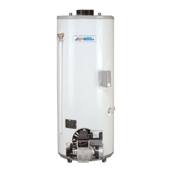
Oil fired water heater
Hide thumbs
Also See for JWF307:
- Installation and operating instructions manual (26 pages) ,
- Installation and operating instructions manual (26 pages)
Table of Contents
Advertisement
OIL FIRED WATER HEATER
INSTALLATION AND OPERATING INSTRUCTIONS
Read and understand these instructions thoroughly before attempting
TABLE OF CONTENTS
Introduction . . . . . . . . . . . . . . . . . . . . . . . . . . . . . .2
II) Safety . . . . . . . . . . . . . . . . . . . . . . . . . . . . . . . . . .3
III) Installation . . . . . . . . . . . . . . . . . . . . . . . . . . . . . .3
Location . . . . . . . . . . . . . . . . . . . . . . . . . . . . . . .3
Air Requirements . . . . . . . . . . . . . . . . . . . . . . . .6
Vent and Exhaust Connections . . . . . . . . . . . . . .7
Oil Supply Connections . . . . . . . . . . . . . . . . . . . .9
Water Supply Connections . . . . . . . . . . . . . . . . .9
Electrical Supply Connections . . . . . . . . . . . . . .10
IV) Operation . . . . . . . . . . . . . . . . . . . . . . . . . . . . . .12
V) Maintenance . . . . . . . . . . . . . . . . . . . . . . . . . . . .13
VI) Combination Heating . . . . . . . . . . . . . . . . . . . . . .16
Warranty . . . . . . . . . . . . . . . . . . . . . . . . . . . . . . .20
PLEASE RETAIN THESE INSTRUCTIONS IN A
SAFE LOCATION FOR FUTURE REFERENCE
WARNING:
Improper installation, adjustment, alter-
ation, service, or maintenance can cause
injury or property damage. Refer to this
manual. For assistance or additional infor-
mation, consult a qualified Oil-Burner
Technician or the oil supplier.
FOR YOUR SAFETY
• Do not store or use gasoline or other
flammable vapors and liquids in the
vicinity of this or any other appliance.
• Installation and service must be per-
formed
by
a
Technician or the oil supplier.
WARNING:
If the information in these instructions is
not followed exactly, a fire or explosion
may result causing property damage, per-
sonal injury or death.
GSW Water Heating is a division of GSW Water Products Inc.
GSW WATER HEATING
599 Hill Street West
Fergus, ON, Canada N1M 2X1
any installation or service.
qualified
Oil-Burner
JWF307 - JW317 - JW327
JWF507 - JW517 - JW527
JWF307V - JW717 - JW727
JWF657
INSTALLATION RECORD
This water heater is protected by a five (5) year warranty against
leaks plus a one (1) year warranty on parts.
Record key data here for future reference and prompt service:
Installed By / Purchased From:
Installation Date:
Model Number
Technical Support Line: 1-888-479-8324
Location of Electrical Switch
or Circuit Protector:
Serial Number
PART NO. 61512 REV. F (05-03)
Advertisement
Table of Contents

Subscribe to Our Youtube Channel
Related Manuals for John Wood JWF307


Summary of Contents for John Wood JWF307
-
Page 1: Table Of Contents
GSW Water Heating is a division of GSW Water Products Inc. any installation or service. JWF307 - JW317 - JW327 JWF507 - JW517 - JW527... -
Page 2: I) Introduction
This is particular- ly important if the water heater is installed in a multi-story building, on finished flooring or carpeted surfaces. GSW WILL NOT ASSUME ANY LIABILITY for damage caused by water leaking from the water heater, pressure relief valve, or related fittings. -
Page 3: Ii) Safety
II) SAFETY Relief Valve Requirements For protection against excessive pressure and/or tempera- tures, an ASME approved Temperature and Pressure (T&P) Relief Valve must be installed in the opening provided and labeled near the hot water outlet. Pressure rating of the valve must not exceed the working pressure shown on the rating plate of the water heater. - Page 4 Venting Components", 63391, that is supplied with the JWF307V. 610mm (24 in.) MIN. FOR SERVICING NON-COMBUSTIBLE FLOOR Flue location Diam. Model Center JWF307 JWF507 JWF657 JWF307V JW317 JW327 JW517 JW527 JW717 JW727 Figure 1 ROUGH-IN DIMENSIONS COMBUSTIBLE CEILING FLUE...
- Page 5 Model JWF307 JWF507 Diam. 27 1/2 1286 1486 50 5/8 58 1/2 1326 1534 52 3/16 60 3/8 1122 1308 44 3/16 51 1/2 1314 1499 51 3/4 Figure 2 INSTALLATION DIMENSIONS (CENTER FLUE MODELS) Model JWF657 JWF307V Diam. 20 5/8...
-
Page 6: Air Requirements
Reduce risk of property damage, severe bodily injury or death from possible flue gas leakage and carbon monoxide emissions. Do not install an exhaust fan in the same room as the water heater. Satisfactory combustion cannot be sustained in an area that is not provided with fresh air. -
Page 7: Air Duct Sizing
appliances in the enclosure, freely communicating with inte- rior areas that have in turn adequate infiltration from the out- side. It shall also have a combustion air supply opening so that the total air received through the opening will be at least as much as would be admitted by openings having a total free area of 4.5 cm /kWh (1 in... -
Page 8: Burner Installation
PASSAGE AT THE HIGHER FIRING RATE. Figure 5 BAFFLE MODIFICATION (JWF307) Power Venting Models JWF307, JWF507 and JWF657 may be power vent- ed with a Field SWGII 4HD Power Venter. The following con- trol kits may be used with the SWGII 4HD: CK 61 Electronic Post Purge. -
Page 9: Oil Supply Connections
Burning Equipment (NFPA 31)” (as applicable), local codes and the manufacturer’s instructions. The burner should be installed only by a qualified Oil-Burner Technician. Oil Supply Connections All aspects of oil tank location and installation, tank size, oil piping supply and burners, including any fittings, valves, fil- ters or any fuel handling components must comply with: •... -
Page 10: Electrical Supply Connections
COLD WATER BREECH SHUT-OFF CONNECTION HOT WATER OUTLET NIPPLE T&P VALVE DRIP TUBE 150 TO 305mm 6 TO 12” Figure 7 PLUMBING CONNECTIONS (CENTER FLUE) up of lime in the T&P valve, there are two recommendations: 1. Install a pressure relief (only) valve in the cold water supply line. - Page 11 R7184 BLACK LIMIT JUMPER WHITE ENVIRACOM™ TERMINAL VALVE VIOLET BURNER MOTOR ORANGE IGNITOR BLUE YELLOW REMOTE ALARM ALARM CIRCUIT CELL YELLOW BURNER JUNCTION BOX R7184 BLACK JUMPER WHITE ENVIRACOM™ TERMINAL VALVE VIOLET BURNER MOTOR ORANGE IGNITOR BLUE YELLOW REMOTE ALARM ALARM CIRCUIT CELL...
-
Page 12: Iv) Operation
Startup NOTE: refer to the instruction manual sup- plied with the burner for installation, start up and adjustment. MAKE SURE THAT THE HEATER IS FULL OF WATER. See “Filling the Water Heater” section. DO NOT ATTEMPT TO START BURNER IF ANY OF THE FOLLOWING CONDITIONS EXIST: 1. -
Page 13: Maintenance
Water Temperature Regulation Once installed, the operation will be completely automatic. The thermostat (aquastat) on the water heater is adjustable and will maintain water at the desired temperature. WARNING Water temperature over 52°C (125°F) can cause severe burns instantly or death from scalds. Children, disabled and elderly are at highest risk of being scalded. -
Page 14: Cathodic Protection
Temperature and Pressure Relief Valve Discharge line to drain Figure 12 T&P VALVE TEST. WARNING! The temperature and pressure relief valve must be manually operated at least once a year. Caution should be taken to ensure that: 1. No one is in front of or around the outlet of the temper- ature and pressure relief valve discharge line. -
Page 15: Anode Maintenance
• Black water can be an indication of organic contami- nates in the water supply. This can be problematic in areas where the water is obtained from surface or cont- aminated sources. Organic particles can develop bacte- rial growth, causing potential health hazards. •... -
Page 16: Re-Starting The Heater After Shut-Down
F280, National/Provincial Building Codes, CSA C22.1, ANSI/NFPA 70, CSA B51 and/or codes having jurisdic- tion. 5. The air handler (fan coil) and/or the circulating pump in a heating loop will require a dedicated 120V circuit. This must be provided and identified for this purpose. - Page 17 HOT WATER TO HOUSE COLD SUPPLY FIXTURE CHECK VALVE (IF USED REQUIRES EXPANSION TANK) MIXING EXPANSION TANK VALVE (OPTIONAL) FLOW 8in TO 12in CONTROL MAX. COLD INLET OUTLET WATER HEATER Figure 14 COMBO HEATING - AIR HANDLER HOT WATER TO HOUSE COLD SUPPLY FIXTURE CHECK VALVE (IF...
- Page 18 96986AJW307 RIELLO R35.3.04.OR RIELLO R35.3.04.OR RIELLO R35.3.04.OR WAYNE HSR "Ecore" BECKETT AFG GSW-J3007 BECKETT AFG GSW-J3009B 0.65 GPH BECKETT AFG GSW-J3008B 0.65 GPH JWF307V CARLIN EZ-1 RIELLO 40 BF3 SBT RIELLO 40 BF3 SBT Table 1 LISTING OF OIL BURNERS.
- Page 19 Model MFGR Burner AERO FAFC-2X AERO SV-2X AERO FAFC-2X AERO SV-2X BECKETT AFG GSW-J5006 BECKETT AFG GSW-J5032 BECKETT AFG GSW-J5031 JWF507 BECKETT AFG GSW-J5041 BECKETT AFG GSW-J5040 BECKETT AFG GSW-J5999 CARLIN EZ196983AJW507 0.75 GPH CARLIN 96983AJW507 RIELLO R35.3.05.OR RIELLO R35.3.05.OR...
-
Page 20: Warranty
GSW will not assume any expense or liability for unauthorized returns, nor repairs made by a person who has not been authorized by GSW or one of its authorized dealers. GSW Units/parts must be replaced with GSW or John Wood products to be eligible for Warranty.
Need help?
Do you have a question about the JWF307 and is the answer not in the manual?
Questions and answers