Table of Contents
Advertisement
Advertisement
Table of Contents

Related Manuals for Garmin Fishfinder 160 Blue


Summary of Contents for Garmin Fishfinder 160 Blue
- Page 1 www.reelschematic.com www.reelschematic.com Fishfi nder 160 Blue owner’s manual...
- Page 2 Information in this manual is subject to change without notice. GARMIN Corporation reserves the right to change or improve its products and to make changes in the content without obligation to notify any person or organization of such changes. Visit the GARMIN web site (www.garmin.com) for current updates and supplemental information concerning the use and operation of this and other GARMIN products.
-
Page 3: Introduction
Thank you for choosing the GARMIN Fishfi nder 160 Blue™. This product is designed for easy operation and to provide years of reliable Introduction service. Please take the time to read this Owner’ s Manual, and learn the opera- tion of your new unit. -
Page 4: Limited Warranty
GARMIN Corporation warrants this product to be free from defects in materials www.reelschematic.com and manufacture for one year from the date of purchase. GARMIN will, at its sole option, repair or replace any components that fail in normal use. Such repairs or Introduction replacement will be made at no charge to the customer for parts or labor. -
Page 5: Packaging And Accessories
www.reelschematic.com www.reelschematic.com The Fishfi nder 160 Blue Standard Package Includes: • Fishfi nder 160 Blue Introduction • Protective Front Cover • Surface Mount Bracket with Knobs Packaging and Accessories • Power/Data Cable • Owner’ s Manual and Quick Reference Guide Label •... -
Page 6: Table Of Contents
www.reelschematic.com www.reelschematic.com Unit Operation...........10-29 Keypad Functions ..............10 Introduction Backlight ................10 Display Information ............... 11 Using the Adjustment Bar: Table of Contents Range ..................12 Zoom ..................13 View..................13 Introduction............i-vi Gain ..................14 Customer Service ..............i Limited Warranty .............. - Page 7 www.reelschematic.com www.reelschematic.com Alarms Tab Fish Alarm ................23 Introduction Shallow Water ................24 Deep Water ................24 Battery Voltage ...............25 Table of Contents System Tab Contrast .................25 Beeper ..................26 On the Water ............ 30-35 NMEA Output................26 Understanding Sonar..............30 Language................26 Transducer Coverage ..............31 Calibrations Tab Understanding the Chart............32 Keel Offset................27 Whiteline ................33...
-
Page 8: Battery Voltage
fi sh is detected. Thermocline and Structure With GARMIN’s See-Thru® technology, the Fishfi nder 160 Blue can display more than just the thermocline and structure. The unit displays fi sh in and below the thermocline, trees, brush and deadfall like you... -
Page 9: Installation
This transducer provides good all-around performance. Other optional dual frequency transducers are available from your local dealer or GARMIN. The transducer transmits sound waves toward the bottom in a cone shape. The wider the cone angle, the larger the coverage area at a given depth. -
Page 10: Transom Mount Installation
If the transducer lead is too short, extension cables Installation are available from you GARMIN dealer. DO NOT cut the transducer lead or any part of the transducer cable, as this will void your warranty. The... -
Page 11: In-Hull Installation
www.reelschematic.com www.reelschematic.com In-Hull Installation To avoid drilling a hole to mount a thru-hull transducer, a transom Installation mount transducer may be used with epoxy inside a boat (also called “shoot- thru-hull” installation). For a transducer to be mounted inside the hull (shoot-thru, not thru-hull), the boat must be fi... -
Page 12: Speed Sensor Installation
www.reelschematic.com In-Hull Installation (continued) www.reelschematic.com Installing the Transducer: Installation 1. Lightly sand the surface of the hull and face of the transducer with 400 grit wet or dry sandpaper. 2. Build a dam using strip caulk about 1/4” tall. Pour about 1/8” of 2-part, Mounting the Transducer/ slow cure epoxy in the dam. -
Page 13: Wiring Harness Installation
Wiring Harness Installation The Fishfinder 160 Blue comes with a wiring harness that connects Installation the unit to power and the transducer with one easy-to-remove connection. Make sure the wiring harness will reach the unit before beginning installation. -
Page 14: Installing The Wiring Harness
www.reelschematic.com www.reelschematic.com Wiring Harness Installation (continued) If your boat does not have a fuse block, the unit can be wired directly Installation to the battery. Make sure the 2-Amp in-line fuse supplied with the unit is installed. The Fishfi nder 160 Blue can be connected to another piece of NMEA- Installing the Wiring Harness compatible electronic equipment. -
Page 15: Display Installation (Surface Mount)
www.reelschematic.com www.reelschematic.com Display Installation (Surface Mount) The Fishfi nder 160 Blue can be mounted to a fl at surface using the Installation supplied Surface Mount Bracket. Surface Mounting the Display: Installing the Display 1. Position the Surface Mount Bracket in the desired location. Leave approximately 2”... -
Page 16: Display Installation (Flush Mount)
www.reelschematic.com www.reelschematic.com Display Installation (Flush Mount) The Fishfi nder 160 Blue can be mounted fl ush against a dash or Installation electronics rack that is no more than 1/4” thick. Flush Mounting the Display: Installing the Display 1. Remove the Mounting Bracket from the back of the unit by removing its four screws. -
Page 17: Testing The Installation
Installation boat should be in the water to properly test the installation. Press the POWER button and the Fishfinder 160 Blue should power on. If the unit fails to power on, verify that the wiring adapter is seated Testing the Installation properly in the back of the unit, the Red and Black wires are connected to the correct polarity, and the 2-Amp fuse is installed and not blown. -
Page 18: Unit Operation
www.reelschematic.com www.reelschematic.com Arrow Keys Unit Operation The ARROW keys are used to select items on the Adjustment Bar and Setup Menu and to change fi eld data. Keypad Functions Enter Key The ENTER key is used to activate/deactivate the Adjustment Bar and Setup Menu data fi... -
Page 19: Display Information
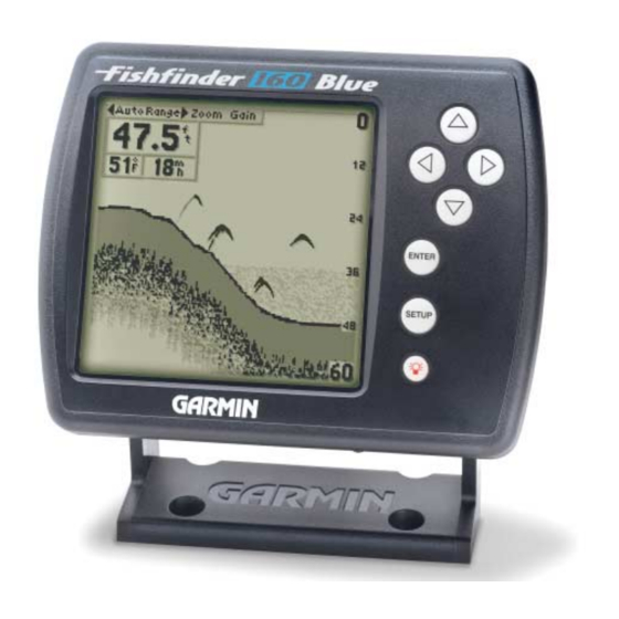
Depth, Battery Voltage, Unit Operation Water Temperature, and Speed Over Water. To provide data on Speed Over Water, the Fishfinder 160 Blue requires an additional speed sensor. The Depth Scale and the Flasher are displayed from top to bottom Describing The Display along the right side of the display. -
Page 20: Using The Adjustment Bar
www.reelschematic.com www.reelschematic.com Using the Adjustment Bar The Adjustment Bar allows direct access to the most commonly Unit Operation changed settings. These include the Depth Range, Zoom setting, and the Gain (sensitivity) of the unit. Place the highlight (white bar) over the desired selection using the The Adjustment Bar RIGHT or LEFT Arrow key, and the current setting will be displayed in the highlight. -
Page 21: Zoom
www.reelschematic.com www.reelschematic.com Zoom The Zoom Adjustment is used to quickly select a display zoom scale. Unit Operation To change the Zoom Scale: 1. Highlight ‘Zoom’ on the Adjustment Bar. The Adjustment Bar 2. Using the UP or DOWN Arrow, select the desired display zoom level. When a scale other than ‘No Zoom’... -
Page 22: Gain
www.reelschematic.com www.reelschematic.com Gain The Gain Adjustment allows the user to control the sensitivity of the unit’ s receiver. This provides some flexibility in what is seen on the display. Unit Operation To see more detail, increase the receiver sensitivity by selecting a higher gain (+). -
Page 23: Setup Menu
www.reelschematic.com www.reelschematic.com SETUP MENU The Setup Menu contains the unit settings that should not require Unit Operation frequent change. The Setup Menu is divided into eight tabs: Chart, Tools, Numbers, Alarms, System, Calibrations, Units, and Memory. Each tab will be described in more detail in this section. Setup Menu: Chart Tab To enter and exit the Setup Menu, press the SETUP button on the face of the unit. -
Page 24: Fish Symbols
www.reelschematic.com www.reelschematic.com Frequency (continued) The wide cone angles associated with low frequencies (40° for 50kHz) provide a large coverage area for fi nding fi sh. However, this also means that Unit Operation wide cone angles produce less bottom detail and resolution. The narrow cone angles associated with high frequencies (10°... -
Page 25: Whiteline
www.reelschematic.com www.reelschematic.com NOTE: When the frequency is set to ‘Dual,’ the appearance of the fi sh symbols will change. Fish returns from the center Unit Operation of the beam will be black, but the fi sh returns from the edges of the beam will be clear. -
Page 26: Scale
www.reelschematic.com www.reelschematic.com Scale The depth ‘Scale’ is displayed vertically along the right side of the chart. Unit Operation The depth ‘Scale’ can be configured to display in four different modes: as an ‘Overlay,’ in the ‘Corners,’ as a ‘Basic’ Scale, or with ‘No Scale.’ To change the Scale Setting: Setup Menu: Chart/Tools Tabs 1. -
Page 27: Tools Tab Depth Line
www.reelschematic.com www.reelschematic.com To change the Depth Line Setting: 1. Place the highlight over the ‘Depth Line’ selection on the Adjustment Bar. Unit Operation 2. Use the UP or DOWN Arrow to change the setting, press ENTER to accept the change. Flasher Setup Menu: Tools Tab With the ‘Flasher’... -
Page 28: Numbers Tab
www.reelschematic.com www.reelschematic.com Noise Reject (continued) To change the Noise Reject Setting: Unit Operation 1. Highlight the ‘Tools’ tab on the Setup Menu. 2. Highlight the ‘Noise Reject’ selection fi eld and press ENTER. Setup Menu: Tools/Numbers Tabs 3. Choose ‘Off,’ ‘Auto,’ or ‘Manual’ and press ENTER. To manually adjust the Noise Reject Setting: 1. -
Page 29: Battery Voltage
Battery Voltage The Fishfinder 160 Blue can display the current battery voltage on Unit Operation the chart. To show or hide the Battery Voltage display fi eld: 1. Highlight the ‘Numbrs’ tab on the Setup Menu. Setup Menu: Numbers Tab 2. -
Page 30: Speed
Speed The Fishfinder 160 Blue can display the boat’ s ‘Speed’ Over Water Unit Operation when equipped with a speed sensor. When set to ‘Auto,’ the unit will automatically sense when a capable sensor is connected and display the boat’... -
Page 31: Fish Alarm
Alarms Tab The ‘Alarms’ tab allows you to activate and configure the four alarms available in the Fishfinder 160 Blue. To access the ‘Alarms’ tab, place the highlight over it using the arrow keys. See page 37 for alarm icons and messages. -
Page 32: Shallow Water
www.reelschematic.com www.reelschematic.com Shallow Water The ‘Shallow Water’ Alarm can be set to sound a warning at a depth Unit Operation determined by the user. The alarm must be activated before the unit will sound a warning. To activate/deactivate the Shallow Water Alarm: Setup Menu: Alarms Tab 1. -
Page 33: Battery Voltage
www.reelschematic.com www.reelschematic.com Battery Voltage When activated, the ‘Battery Voltage’ Alarm will warn you when the Unit Operation battery voltage reaches a user determined state of discharge. To activate/deactivate the Battery Voltage Alarm: 1. Highlight the ‘Alarm’ tab on the Setup Menu. Setup Menu: Alarms/System Tabs 2. -
Page 34: Beeper
www.reelschematic.com www.reelschematic.com Beeper The ‘Beeper’ fi eld contains three settings: ‘Off,’ ‘Alarms Only,’ and ‘Key Unit Operation & Alarm.’ To change the Beeper Setting: 1. Highlight the ‘System’ tab on the Setup Menu. Setup Menu: System Tab 2. Highlight the ‘Beeper’ fi eld and press ENTER. 3. -
Page 35: Calibrations Tab
www.reelschematic.com www.reelschematic.com Calibrations Tab The ‘Calibrt’ tab contains the ‘Keel Offset’ and ‘Water Type’ setups, and a ‘Calibrate Speed’ function for use when a speed sensor is installed. Unit Operation Keel Offset The ‘Keel Offset’ fi eld allows the user to offset the depth reading for a keel or for the draw on a larger vessel. -
Page 36: Units Tab
www.reelschematic.com Units Tab www.reelschematic.com The ‘Units’ tab contains settings for ‘Depth,’ ‘Temperature’ and ‘Speed.’ To access the ‘Units’ tab, use the arrow keys to highlight it. Unit Operation Depth The ‘Depth’ fi eld can be confi gured to display in Feet (ft), Meters (m) or Fathoms (fa). -
Page 37: Memory Tab
www.reelschematic.com www.reelschematic.com Memory Tab The ‘Memory’ tab contains the settings for unit memory and allows you Unit Operation to reset the unit to the factory settings and review the software version. To access the ‘Memory’ tab, use the arrow keys to highlight it. Remember Setup Menu: Memory Tab The Fishfi... -
Page 38: On The Water
On the Water On the Water is intended to help the novice user gain some understanding of how the Fishfinder 160 Blue operates and how it can help improve their fishing Unit Operation and the Chart productivity. To understand what the unit is displaying, it is important to have a general knowledge of how the unit works and how it determines what to display. -
Page 39: Transducer Coverage
10° cone angle (200kHz frequency) approximately covers the area of a 6 foot diameter circle at a 30 foot depth. When using the Fishfinder 160 Blue in ‘Dual’ frequency mode, the unit transmits both 50kHz and 200kHz signals at the same time. The ‘Dual’... -
Page 40: Understanding The Chart
www.reelschematic.com www.reelschematic.com Understanding the Chart It is important to understand that the unit does not display a 3-D On the Water On the Water representation of the underwater environment. The unit can display mul- tiple things at the same time, but cannot determine from where the return originated. -
Page 41: Whiteline
www.reelschematic.com www.reelschematic.com Whiteline The Fishfi nder 160 Blue can help you to determine if the bottom is On the Water On the Water hard or soft. When the sonar soundwaves are refl ected back by the bottom, a hard bottom will return a stronger signal than a soft bottom. The stronger the bottom return, the wider the bottom layer is displayed. -
Page 42: Thermoclines
One of the unique features offered by GARMIN is See-Thru technology. Understanding the Chart A benefit of See-Thru technology is that it allows the Fishfinder 160 Blue to see fish inside thermoclines. Thermocline... -
Page 43: Simulator Mode
Fishfinder 160 Blue can be controlled just as if it were on the water. Using simulator mode allows the user to practice and learn the operation of the Simulator Mode unit without having to be on the water. -
Page 44: Appendix A: Specifi Cations
www.reelschematic.com www.reelschematic.com Physical Case: Fully gasketed, high-impact plastic alloy On the Water Appendix A Display: 3.3” x 3.3” (8.3 x 8.3 cm), 4.6” diagonal (11.7 cm), 160 H x 160 W pixels, FSTN LCD with incandescent backlighting Size: 4.93” H x 6.3” W x 3.0” D (12.5 x 16 x 7.6 cm) Specifi... -
Page 45: Appendix B: Alarm Messages And Icons
Alarm Messages and Icons The Fishfinder 160 Blue displays a message when an alarm is tripped. On the Water Appendix B To clear the message, press the ENTER key. If the ENTER key is not pressed, the unit will automatically remove most messages after 10 seconds... -
Page 46: Appendix C: Index
www.reelschematic.com www.reelschematic.com Deep Water Alarm................24 Depth Line ...................18-19 On the Water Appendix C Depth Number ................22-23 Depth Range..................12 Depth Scale ..................18 Index Depth Units..................28 Display..................vi, 11 Display Installation................7-8 Accessories ..................iii Adjustment Bar ................12-14 Enter Key ..................10 Alarm Messages.................37 Alarms Tab .................. - Page 47 www.reelschematic.com www.reelschematic.com Keel Offset..................27 Keypad....................10 On the Water Appendix C Language...................26 Index Limited Warranty ................ii Memory Tab ..................29 Scale....................18 Messages ...................37 Scroll Speed ..................17 Mounting the Display..............7-8 Setup Key..................10 Mounting the Speed Sensor..............4 Setup Menu.................15-29 Mounting the Transducer ..............2-4 Shallow Water Alarm................
- Page 48 www.reelschematic.com www.reelschematic.com On the Water Appendix C Index Tools Tab..................18-20 Transducers.................. 1, 31 Transom Mount Installation ............... 2 Understanding Sonar................ 30 Understanding the Chart.............32-34 Units Tab..................28 View Adjustment................13 Warranty .................... ii Water Depth................vi, 28 Water Temperature..............vi, 21, 28 Water Type ..................
- Page 49 www.reelschematic.com www.reelschematic.com...
- Page 50 © 2001 GARMIN Corporation GARMIN International, Inc. 1200 East 151st Street, Olathe, Kansas 66062, U.S.A. GARMIN (Europe) Ltd. Unit 5, The Quadrangle, Abbey Park Industrial Estate, Romsey, SO51 9AQ, U.K. GARMIN Corporation No. 68, Jangshu 2 Road, Shijr, Taipei County, Taiwan www.garmin.com...
Need help?
Do you have a question about the Fishfinder 160 Blue and is the answer not in the manual?
Questions and answers