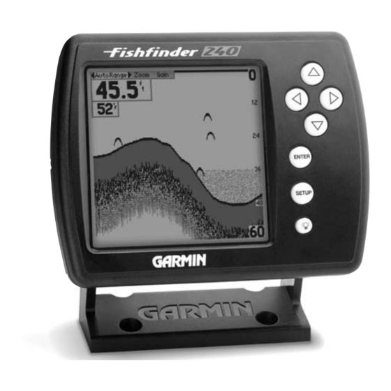
Garmin Fishfinder 240 Owner's Manual
Hide thumbs
Also See for Fishfinder 240:
- Owner's manual (50 pages) ,
- Pilot's manual (12 pages) ,
- Specifications (2 pages)
Advertisement
Quick Links
Advertisement

Related Manuals for Garmin Fishfinder 240


Summary of Contents for Garmin Fishfinder 240
- Page 1 Owner ’s Manual...
-
Page 3: Table Of Contents
Table of Contents ACKAGING AND CCESSORIES NTRODUCTION NSTALLATION PERATION ETUP N THE ATER IMULATOR PPENDIX... -
Page 4: Packaging And Accessories
Packaging and Accessories WHAT SHOULD BE IN THE BOX • Fishfinder 240 • Protective Front Cover • Surface/Flush Mount Kit • Wiring Adapter Cable • Owner’s Manual • Quick Reference Guide • Transom Mount Transducer (w/depth/temp) * Optional 010-10200-00 Trolling Motor Mount (w/depth/temp) - Page 5 Introduction HOW THE FISHFINDER WORKS...
- Page 6 Thermocline a a nd S S tructure With ’s See-Thru technology the Fishfinder 240 can display more than just the thermocline and structure, the unit displays fish in and below the thermocline, trees, brush and deadfall like you have never seen before! Bottom T T ype a a nd S S hape ’s unique DCG...
- Page 7 Installation TRANSDUCER SELECTION...
- Page 8 Installation TRANSDUCER INSTALLATION DO NOT mount the transducer behind strakes, struts, fittings, water intake or discharge ports, or anything that creates air bubbles or causes the water to become turbulent. It is important that the transducer be in clean (non turbulent) water for optimal performance.
- Page 9 Installation INSTALLING THE WIRING ADAPTER DO NOT...
- Page 10 Installation INSTALLING THE WIRING ADAPTER During a typical installation, only the Red and Black wires are used. The Blue wire supplies NMEA data, and doesn’t have to be connected for normal operation of the unit.
- Page 11 Installation SURFACE MOUNTING 1. Position the Surface Mount in the desired location. Leave approximately 2'' behind the unit for cable clearance. 2. Mark and drill the four mounting holes for the fasteners you are using (not included). 3. Secure the mount to the surface using the appropriate fasteners. 4.
- Page 12 Installation FLUSH MOUNTING 1. Using the mounting bracket as a template, mark the location of the four mounting holes and the center relief hole. 2. After carefully marking these locations drill the mounting holes using either a 6mm or 15/64” drill. 3.
- Page 13 Installation TESTING THE INSTALLATION When adjusting the depth of the transducer, make the adjustments in small increments. Placing the transducer too deep can adversely affect the boat’s performance and place the transducer at greater risk of striking underwater objects.
-
Page 14: Unit Operation
Unit Operation DESCRIBING THE DISPLAY Adjustment Bar Depth Battery Voltage Water Temp Speed Through Water Depth Scale Flasher Alarm/Message Icons... - Page 15 Unit Operation THE ADJUSTMENT BAR White Highlight Current Setting Adjustment List...
- Page 16 Unit Operation THE ADJUSTMENT BAR Range Zoom...
- Page 17 Unit Operation THE ADJUSTMENT BAR View Gain...
-
Page 18: Setup Menu
Unit Operation SETUP MENU Setup Menu... - Page 19 Unit Operation — SETUP MENU CHART Chart Fish S S ymbols Fish S S ymbols O O ff—All available information will be displayed Fish S S ymbols O O n—Suspended targets will display as fish symbols. Background information will be displayed Fish S S ymbols O O n—Same as above with the target depth attached Fish S S ymbols O O n—Suspended targets display as fish symbols.
- Page 20 Unit Operation — SETUP MENU CHART Whiteline Scroll S S peed...
- Page 21 Unit Operation — SETUP MENU CHART Scale...
- Page 22 Unit Operation — SETUP MENU TOOLS Tools Depth L L ine...
- Page 23 Unit Operation — SETUP MENU TOOLS Noise R R eject Flasher Sim T T ransducer...
- Page 24 Unit Operation — SETUP MENU NUMBERS Numbers Number S S ize Battery V V oltage...
- Page 25 Unit Operation — SETUP MENU NUMBERS Temperature Speed...
- Page 26 Unit Operation — SETUP MENU ALARMS Alarms Fish A A larm Shallow W W ater...
- Page 27 Unit Operation — SETUP MENU ALARMS Deep W W ater Battery V V oltage...
- Page 28 Unit Operation — SETUP MENU SYSTEM System Contrast Beeper...
- Page 29 Unit Operation — SETUP MENU SYSTEM NMEA O O utput Language...
- Page 30 Unit Operation — SETUP MENU CALIBRATION Calibration Keel O O ffset Water T T ype...
- Page 31 Unit Operation — SETUP MENU CALIBRATION Calibrate S S peed...
- Page 32 Unit Operation — SETUP MENU UNITS Units Depth Temperature...
- Page 33 Unit Operation — SETUP MENU UNITS Speed...
- Page 34 Unit Operation — SETUP MENU MEMORY Memory Remember Factory S S etup Software V V ersion...
-
Page 35: On The Water
On the Water UNIT OPERATION AND THE DISPLAY... - Page 36 On the Water TRANSDUCER COVERAGE ’s...
- Page 37 On the Water UNDERSTANDING THE DISPLAY...
- Page 38 On the Water DETERMINING THE BOTTOM TYPE...
- Page 39 On the Water THERMOCLINES Thermocline...
-
Page 40: Simulator
Simulator USING THE SIMULATOR MODE Simulator... - Page 41 Appendix A SPECIFICATIONS Physical Power Performance NMEA 0183 V 2.0...
- Page 42 Appendix B MESSAGES AND ALARM ICONS...
- Page 43 Appendix C INSTALLING THE QUICK REFERENCE GUIDE...
- Page 44 Appendix D INDEX...
- Page 45 Appendix D INDEX...
- Page 46 Appendix D INDEX...
- Page 47 Notes...
- Page 48 Notes...
- Page 49 LIMITED WARRANTY...
- Page 50 1999 GARMIN Corporation 1200 E. 151st Street, Olathe, KS USA 66062 Garmin (Europe) Ltd. - Unit 5, The Quadrangle, Abbey Park, Romsey, UK S051 9AQ Garmin (Asia) Corp. 3F, No.1, Lane 45, Pao Hsing Road, Hsin Tien, Taipei, Taiwan, R.O.C.
Need help?
Do you have a question about the Fishfinder 240 and is the answer not in the manual?
Questions and answers